Abstract
An estimation of the local Nusselt number distribution for a flat and a ribbed surface from transient liquid crystal images is presented. Liquid crystal thermography generates color images of the time-varying surface temperature field, when an initially heated surface is subjected to cooling in forced flow. The inverse technique compares the approximate numerical solution with the transient experimental temperature distribution, and enforces the applicable physical laws in such a way that a globally correct Nusselt number distribution is predicted. The related optimization problem has been solved by a conjugate gradient method, with a stabilization scheme based on additional experimental data. The partial differential equations arising at the intermediate stages have been solved numerically using the finite difference technique. Predictions of the local Nusselt number have been compared with the full numerical solution based on unsteady incompressible laminar flow, as well as the one-dimensional semi-infinite solid approximation applied to experimental data. Reynolds numbers considered in the study are 160 and 260, based on the rib height. Results show that the inverse technique is capable of resolving sharp as well as gradual changes in the heat transfer rates for the flat plate and the rib geometries. The peak in the Nusselt number distribution for flow past a rib is seen to fall at a location where the flow reattaches with the flat surface. The inverse technique is robust with respect to signal length, and within limits it is insensitive to noise in the experimental data.
1. Introduction
Convective heat transfer coefficient distribution over a flat surface with and without a surface-mounted rib has been studied in the present work. The rib geometry is encountered in many applications, for example as a vortex generator for cooling of gas turbine blades. Flow separates at the corners of the rib, generating vortices over the surface. The vortex that is formed beyond the rib improves mixing of the warm fluid near the solid surface with the cooler free stream, and is the source of heat transfer enhancement. Specifically, it creates a local Nusselt number peak at the reattachment point. The present work is concerned with determining the distribution of local Nusselt number over the solid surface. Liquid crystal thermography (LCT) has been employed under transient cooling conditions of the wall. The LCT images form the input data to an inverse technique, from which the local Nusselt number distribution is calculated. Results have been reported in the present work for a lower range of Reynolds numbers, for which the vortices are steady. The overall methodology is however robust with respect to the form of thermal boundary conditions and is independent of Reynolds number.
The importance of inverse techniques is well-discussed in the literature in the context of heat conduction Citation[1, Citation2]. When heat transfer is by mechanisms of conduction, as well as convection, the methodology is not as well-established. Fluid flow introduces new physics such as boundary-layers and vortex formation, that in turn localizes the region where sensitive information is contained. Huang and Ozisik Citation[3] presented a solution to the parabolic inverse forced convection problem using conjugate gradient method to estimate the surface heat flux in a parallel plate channel. Huang and Chen Citation[4] and Colaco and Orlande Citation[5] used the conjugate gradient method to solve two-and three-dimensional inverse convection problems, respectively. The geometries considered were a flat surface and an irregularly shaped channel. These references utilized numerically simulated data, rather than from experimental measurements. Specifically, the potential of an inverse technique to extract useful information from experimental data has not been largely reported.
As an experimental technique, LCT is a powerful tool for measuring the surface temperature distribution with subsequent determination of surface Nusselt number. Various aspects of liquid crystal thermography have been addressed in the literature Citation[6–Citation10]. Lin and Wang Citation[11] presented a method of calculating the local Nusselt number by an inverse conduction technique using LCT images as well as temperature data within the solid medium. These authors have also shown that a one-dimensional model overestimates the local Nusselt number, with respect to the two-dimensional model. A semi-infinite solid solution for determining the local Nusselt number has been described in Citation[12, Citation13].
A two-dimensional inverse convection algorithm has been presented in this work for flow over heated surfaces. A flat plate and one with a surface-mounted rib have been considered. The flow and the thermal fields have been taken to be two-dimensional, with the wall being initially isothermal. The Reynolds numbers realized in the experiments make the flow laminar and steady over the physical domain. The experimental data in the form of temperature history of the surface has been collected using the LCT technique. A collection of LCT images serve to stabilize the calculations against noise in the experimental data, and the intrinsic ill-posedness of the inverse algorithm. The objective of the present work is to determine the steady state distribution of Nusselt number from a slow transient cooling experiment.
2. Apparatus and instrumentation
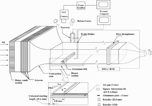
The sketch of the experimental setup along with the instrumentation used in the present work is shown in . The experimental facility comprises a flow circuit, heating section, traversing mechanism, liquid crystal sheets, and an image processing system. Experiments have been performed in the open-loop wind tunnel in which air is drawn into the test section through a honeycomb section, five anti-turbulence screens and a 3:1 contraction cone. The test section is followed by a flow straightener to minimize the influence of blower noise in the test section. The speed of the blower is controlled by a speed controller (Victor G1000 Kirloskar Electric). The settling chamber is 1950 mm long and has a rectangular cross-section of 500 mm by 1000 mm. The test section over which measurements have been carried out is 800 mm long with cross section of 298 mm × 160 mm in the vertical plane. The entire test section is made of a 12 mm thick perspex sheet. The free-stream turbulence level at the entrance of the test cell was measured to be 0.5% for the velocity range used in this work. The boundary-layer thickness at the inflow plane was measured to be 3 mm. The measured inflow velocity profile was used as a boundary condition in the numerical calculations.
The test surface over which the heat transfer rates are determined is a single aluminum plate (680 mm × 298 mm × 3 mm) heated by stainless steel foils of dimension 680 mm × 47 mm × 0.045 mm. The foils are connected in series and glued uniformly between the aluminum plate and a 25-mm thick bakelite sheet. A DC power source supplies power to the stainless steel foil heaters. To minimize the conductive heat losses, the lower surface of the bakelite sheet is insulated using a 13-mm thick plate of bakelite with a 2 mm air gap in between. The heat transfer surface is instrumented with 13 calibrated thermocouples, mounted onto the bakelite plate at several locations with thermally conducting epoxy (101, Omega). For measurements with a surface-mounted rib, an aluminum rod of uniform cross section (6.5 mm × 6.5 mm) is firmly glued over the test surface. The rib was not seen to influence the velocity and temperature profiles at the inlet plane.
All fluid velocity measurements have been carried out with a single-wire hotwire anemometer (DANTEC, 56C17). The hot-wire calibration has been performed in the test cell itself due to its high degree of uniformity and low fluctuations. Temperature profiles in the flow field have been measured by the hotwire probe working as resistance thermometer. The resistance of the wire is determined by a 5.5-digit multimeter (HP 3457A). Thermocouples are connected to a data acquisition card (NI 4351), with room temperature compensation against a precalibrated thermistor mounted on the terminal block itself. The hotwire probe is positioned by a computer-controlled traversing mechanism that has an accuracy of ± 0.1 mm.
The temperature variation over the test surface has been measured by liquid crystal thermography (LCT). The heated surface is coated with the thermochromic liquid crystal sheet (Hallcrest R35C5W), whose activation of the red color begins at 35°C, the bandwidth being 5°C. The image acquisition and processing system used in the present investigation consists of a color CCD video camera (Sony XC-003P), a 24-bit true color image processing board (Imaging Technology), and a high speed PC (HCL). The camera resolution is 768 × 574 pixels over the selected surface. The image-processing board is programmed for color analysis and stores the calculated RGB value to integers ranging from 0 to 255. Further, it provides hue, saturation and intensity (HSI) values directly using base level C-language programs.
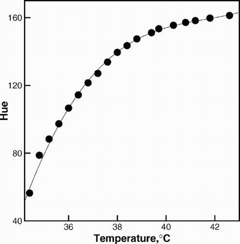
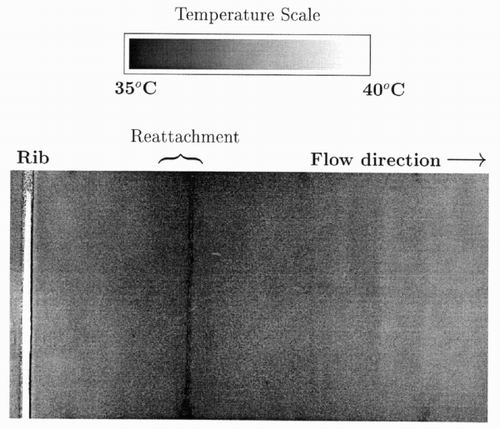
For calibration of the liquid crystal sheet, the color image of the area around the thermocouple mounted on the test surface is recorded and the corresponding HSI values are calculated. For the range of temperatures studied, hue was found to have a monotonic variation with temperature. In addition, the variance in the scatter of hue with temperature was a minimum, in comparison to saturation and intensity. Therefore, hue was identified as the most suitable quantity for representing the relationship between color and temperature. The type of illumination, source to model distance, illumination angle, camera conditions, such as circuit gain, filter adjustment, aperture and optical adjustments influence this relationship, and are locked during calibration as well as the final image acquisition. A calibration curve relating hue to temperature is shown in . A typical surface temperature variation from the liquid crystal images of flow past a rib using the calibration curve (shown in ) has been presented in on a grey scale. In the reattachment region, (darker region) the temperature is a minimum due to the higher heat transfer coefficient.
Figure 3. Normalized grey scale ribbed surface temperature from the transient liquid crystal image after 90 s at Re = 260.
Scatter in the experimental data is associated with measuring temperature via the A/D card, fluctuations in the supply voltage, positional accuracy in locating the probe, scatter in the calibration data, and inadequate compensation for room temperature, drift in electronics, non-uniformity in the illumination on the liquid crystals, and the pixel size resolution of the camera. Careful control over each of these factors showed that the LCT images were practically unchanged for a Reynolds number perturbation upto ± 10%. A sensitivity study of the effect of scatter in the LCT data on the predicted Nusselt number distribution has been reported in this work.
The thermophysical properties of air used in the present study are listed in .
Table 1. Thermophysical properties of air at 30 and 40°C.
3. Experimental procedure
A transient experiment to estimate the local Nusselt number distribution is performed as follows. With the flow turned off, the test section, namely the aluminium plate is electrically heated from below. In view of the high thermal conductivity of aluminium, its surface achieves a practically constant temperature. The heating is stopped when the maximum temperature between any pair of points over the test surface is within ± 0.2°C, with respect to the mean value. This check is enforced via the surface-mounted thermocouples, as well as by examining the color variation of the LCT sheet. In a typical experiment, the wall flux is around 1000 W/m2 and heating takes around 4 min. During this period, the penetration of the thermal front in the bakelite sheet is negligible. The test surface is then subjected to cooling by turning the heater off, and the fan blower on. It takes about 10 s for the flow to be established in the wind tunnel, and can be monitored by the static pressure taps in the flow direction. The rate of cooling of the test section is subsequently recorded by monitoring the change in the color patterns of the liquid crystal sheets as a function of time. Liquid crystal images have been recorded for all experiments for a period of 30 s. An interval of 2 s is allowed to elapse between two successive images. The total time taken for the LCT sheet to pass through its entire bandwidth is of the order of a few minutes. The LCT images are converted to hue and then a temperature distribution by employing the calibration curve. At the Reynolds numbers studied, the temperature distribution in the spanwise direction with respect to flow was found to be practically uniform. The temperature data was averaged in this direction before being used as input to the unsteady two-dimensional inverse technique. Spanwise averaging also helped reduce noise in the data supplied to the inverse algorithm.
4. Inverse convection technique
The application of the inverse technique for the determination of the local Nusselt number distribution from the sequence of the LCT images is discussed in the present section. A flat surface and another carrying a rib have been studied. The inverse technique is developed around an optimization algorithm. Among the family of optimization algorithms available, the one based on conjugate gradients has been utilized in the present work. The conjugate gradient method uses the steepest descent technique coupled with orthonormalization of the present and the previous search directions. When applied to the inverse procedure, the conjugate gradient method uses a perturbation principle and generates a sequence of direct, adjoint and sensitivity problems. In every iteration, the three problems are solved once. Iterations continue till the predicted Nusselt number distribution attains convergence.
Though the algorithm presented in this section is quite general, specific results have been presented with the following approximations.
| 1. | The velocity field is steady and two dimensional. | ||||
| 2. | The temperature field is unsteady and two dimensional, i.e. the surface temperature varies with the streamwise coordinate alone. | ||||
| 3. | Over the brief duration of the experiment, the local Nusselt number distribution is time-invariant. | ||||
| 4. | As the rib-to-channel height ratio (=1: 24) is small, the full channel simulation is replaced by an external flow configuration, wherein the free-slip condition is applied for velocity at a distance of y = d. This step reduces the number of nodes involved in the computation. | ||||
| 5. | The dominant mechanism of heat transfer in the fluid is forced convection; thus thermal buoyancy forces can be neglected and the momentum and energy equations can be decoupled. | ||||
The two-dimensional steady velocity field is computed by solving continuity and Navier–Stokes equations through the stream function–vorticity approach. The inflow velocity profiles have been taken from the experimental measurements, 10 rib-heights upstream of the rib.
The direct problem for temperature requires the solution of the following energy equation:
The wall boundary condition for temperature for a transient experiment is written in such a way that the Nusselt number distribution is brought into prominence. The wall temperature is initially unity, and provides a non-trivial condition for the system of Equationequations (1)–Equation(6). For a guessed Nusselt number variation over the surface, the wall temperature at all subsequent times can be determined as a part of the solution of the direct problem.
Heat transfer within the rib is by conduction. It is coupled to the energy equation in the fluid phase as a conjugate problem in terms of the following set of equations: For
Symbols appearing in the boundary conditions above are explained in the nomenclature. The treatment given above allows the rib material to have a finite thermal conductivity and hence temperature gradients within the rib.
4.1. Inverse problem
With θ(x, y, t) determined from the direct problem, the plate temperature distribution is obtained for a guessed wall Nusselt number variation. The inverse procedure is developed by comparing this instantaneous temperature distribution with the appropriate LCT image of the experiment.
Following the earlier work of Citation[3] and Citation[4], the global statement of the inverse problem has been posed in the form of minimization of the following functional:
4.2. Adjoint equations
The minimization of the functional in the inverse technique is accomplished jointly with the constraint of the physical law that governs unsteady forced convection heat transfer. The constraint is introduced in the formulation via the principle of Lagrange multipliers. Introducing the Lagrange multiplier function λ, the optimization functional can be rewritten as:
In Equationequation (11), setting θ + Δθ in place of θ and J + ΔJ in place of J, subtracting the original from the resulting equation and neglecting the terms involving squares of Δθ, the perturbation ΔJ can be derived as:
The related problem of heat conduction in the rib reduces to: For
4.3. Sensitivity problem
The sensitivity problem refers to the determination of the domain of dependence of the temperature field on the unknown local Nusselt numbers. It arises naturally in the conjugate gradient algorithm, during the calculation of the step size for corrections in the guessed Nusselt number. To formulate the sensitivity problem, a perturbation of Δθ is given to θ in Equationequations (1)–Equation(9). Subtracting the original from the perturbed equations, the following sensitivity problem and boundary conditions are obtained:
The corresponding heat conduction equation and boundary conditions in the rib can be derived as: For
4.4. Determination of step size
The value of the functional is Jk at the kth iteration and becomes J k + 1 after temperatures are updated through a step size of β k in Nusselt number. The condition for the step size to be an optimum is
4.5. Stopping criterion
The inverse technique is iterative in nature, and iterations are to be stopped when a suitable convergence criterion is satisfied. When the standard deviation in the measured data is known, the convergence criterion in Nusselt number can be related to the scatter in the temperature data. In the present study, the additional measurement approach of Ozisik and Orlande Citation[2] has been adopted as the stopping criterion. A new functional J 1 is constructed with a few of the LCT images beyond the measurement time tf , with the following definition:
4.6. Inverse algorithm
The statement of the full inverse algorithm can be summarized as follows:
| 1. | Solve stream function and vorticity equations for the velocity field. | ||||
| 2. | Provide an initial guess to the local Nusselt number distribution. | ||||
| 3. | Solve the direct problem (Equationequations 1–Equation9) and obtain the instantaneous plate temperature distribution. | ||||
| 4. | Compute the functional (Equationequation 11). | ||||
| 5. | Solve the adjoint problem (Equationequations 13–Equation21). | ||||
| 6. | Compute the gradient of the functional (Equationequation 24). | ||||
| 7. | Compute the descent direction: where for the first iteration γ1 = 0. For k>1 | ||||
| 8. | Solve the sensitivity problem (Equationequations 25–Equation33). | ||||
| 9. | Compute the step size (Equationequation 38). | ||||
| 10. | Compute the updated local Nusselt number: | ||||
| 11. | Go to step 3, if the stopping criterion (Equationequation 40) is not satisfied. | ||||
5. Semi-infinite solid approximation
For comparison with the inverse solution, an alternative approach has also been pursued. It is based on temperature measurements in the bakelite sheet below the heated aluminum plate. When the heaters are turned off, the aluminum plate cools because of the flow above the surface. This process influences the thermal gradients in the bakelite sheet. The thermocouples embedded in the bakelite sheet sense this change as a function of time. The temperature measurements can be related to the surface heat transfer coefficient. The mathematical model for heat conduction in the bakelite sheet assumes that temperature changes occur in a direction normal to the flow direction; equivalently, the bakelite sheet is taken to be a semi-infinite solid.
In view of the computational efficiency of the semi-infinite solid approximation, it has been discussed by various authors Citation[11–Citation13]. The procedure presented here has been adopted from Citation[12, Citation13]. The selection of the bakelite and its thickness satisfy the criterion that the minimum thickness of the bakelite sheet should be greater than
6. Steady state calculations
The steady state solution for Nusselt number can be independently found without reference to experimental data. These results have been used in the present work for comparison against the predictions of the inverse technique.
For an isothermal surface, the direct solution of the temperature distribution in the fluid medium is achieved by solving Equationequations (1)–Equation(9), with the boundary condition:
For a constant flux boundary condition, the wall boundary condition is
7. Numerical simulation
The intermediate steps in the inverse algorithm require the solution of partial differential equations subjected to initial and boundary conditions. These equations have been solved in the present study by appropriate numerical algorithms Citation[14]. Specifically, the finite difference method of discretization has been used. Advection terms have been treated by the QUICK scheme. Central differencing has been used for the diffusion terms. Velocity field is solved by the stream function–vorticity approach. Vorticity transport equation is solved through explicit time-marching, whereas a Poisson equation for stream function is solved at every time step. Energy, adjoint and sensitivity equations are solved in a fully implicit manner. The time step for explicit time-marching is taken to be the smaller of the minimum of the grid Courant number and the grid Fourier number. For implicit time-marching, the time step is restricted to be less than ten times the explicit time step. A Compaq Pentium-4 PC with 512 MB SDRAM and a LINUX operating system has been used for computation.
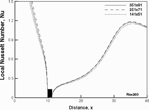
The grid independence test has been carried out for three different grid sizes namely, 151 × 41, 251 × 71 and 351 × 91, at the highest Reynolds number of the present study. Based on this comparison, a 251 × 71 grid has been chosen for presenting the results. The grid is kept denser near the heated surface, and near the rib. The grid size increases in a geometric progression in the downstream direction. A grid independence test in terms of the local Nusselt number distribution is shown in .
Figure 4. Grid independence test for the two-dimensional flow and energy equation solvers in terms of the local Nusselt number distribution.
The computer codes have been extensively validated against published numerical results ( and ). The fluid flow code has been compared with the published numerical solution for laminar flow over a backward facing step Citation[15]. The Reynolds number in the simulation is 800 based on the channel height. The backward facing step occupies half of the channel height. The profiles have been compared at streamwise locations of x = 7 and x = 15 in . The comparison is seen to be quite good.
Figure 5. Validation of the two-dimensional flow solver for flow over a backward facing step with Gartling Citation[15], at Re = 800.
![Figure 5. Validation of the two-dimensional flow solver for flow over a backward facing step with Gartling Citation[15], at Re = 800.](/cms/asset/c80b3c59-a75e-4a40-9361-d4e08da29bf5/gipe_a_10050473_o_fig005g.gif)
Figure 6. Validation of the two-dimensional thermal energy equation solver against Leung et al. Citation[16] for flow past a heated block mounted on a flat surface.
![Figure 6. Validation of the two-dimensional thermal energy equation solver against Leung et al. Citation[16] for flow past a heated block mounted on a flat surface.](/cms/asset/d38dd060-ad26-4bcf-b858-ff98fa4376ac/gipe_a_10050473_o_fig006g.gif)
The energy equation solver has been compared with the numerical solution of flow past a heat generating obstacle Citation[16]. Three different Reynolds numbers have been studied, namely 100, 200 and 300. The channel height has been taken to be the characteristic dimension. The channel walls are insulated and heat transfer over the obstacle surface to the fluid has been computed. The comparison shown in reveals that local peaks in Nusselt number have been captured along with the overall trend.
8. Results and discussion
The local Nusselt number variations for flow over a flat and a ribbed surface are presented in this section. Nusselt number values quoted in this study are based on the rib height. Issues such as the length of the signal in the transient experiment and the effect of noise in the measured data are discussed. Reynolds numbers of 160 and 260, based on the rib height, are considered. For the flat surface, the air velocity that prevailed in the wind tunnel at the respective Reynolds numbers of the rib experiment was retained. For comparison, the Nusselt number distribution from a fully numerical calculation on a fine grid has been included. To estimate uncertainties in the data inversion procedure, constant temperature and constant flux boundary conditions have been considered. As discussed in section 3, the aluminum plate is practically isothermal when the transient cooling experiment is initiated.
shows the performance of the inverse algorithm and the semi-infinite solid solution for flow over a flat surface. The limiting Nusselt number distributions for a constant wall temperature and a constant wall flux are also shown. The prediction of Nusselt number from the inverse technique is very close to that from the steady state calculation with an isothermal boundary condition. It is consistent with the initial condition of the test plate, before the transient experiment is commenced by turning the heater off. In this respect, the inverse technique converges to the initial steady state condition prevailing in the test section, and not the transient cooling of the plate. In contrast, the prediction of the semi-infinite solid approximation varies with the duration of the transient experiment. For this reason, a sensitivity study with respect to a signal length of upto 90 s has been carried out. For a signal length of the first 20 s, the Nusselt number variation in matches well the profile of the constant temperature boundary condition. With increasing signal length (= 90 s), the prediction departs from that for an isothermal plate. It is however, bounded by the Nusselt number distribution for constant wall heat flux. This result is consistently to be seen at both Reynolds numbers.
Figure 7. Local Nusselt number as a function of dimensionless distance for convective heat transfer over a flat surface.
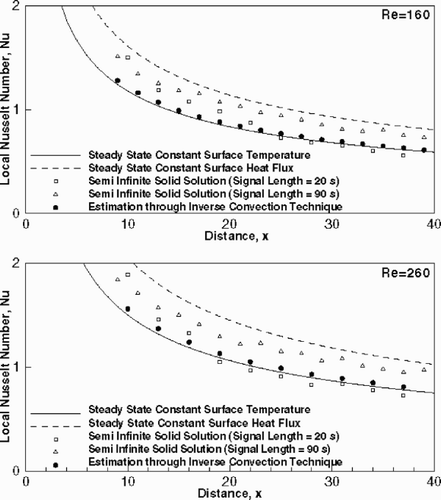
The above observation on the signal length is in agreement with the numerical results of Butler and Baughn Citation[17]. It can be explained as follows: The assumption of a semi-infinite solid exposed to a constant Nusselt number environment during the transient experiment breaks down for long signal lengths. This leads to a large deviation from the steady state Nusselt number distribution for an isothermal surface. In contrast, the inverse technique builds into the optimization scheme the physical implication of plate cooling (through the adjoint equations) and uniquely predicts the initial Nusselt number distribution. The long-signal predictions of the semi-infinite solid model approach those for constant heat flux, because the measured thermocouple data is then conditioned by the practically zero heat flux at the wall.
A survey of the literature shows that the semi-infinite solid approximation has been examined closely by various authors. The time variation of the local Nusselt number in the transient LCT experiment for a flat plate has been examined in Citation[17]. The authors have suggested the following correction to the transient solution to evaluate steady constant surface temperature solution:
A second source of error in the semi-infinite solid approach is that it neglects heat capacity effects in the LCT sheet as well as the heating element. In contrast, the inverse convection technique works with the thermal field data in the fluid phase and is free of this error. von Wolfersdorf et al. Citation[18] have shown that this factor, along with three-dimensional heat conduction effects in the supporting solid medium, can over-predict the local Nusselt number. This trend has also been observed consistently in the present study.
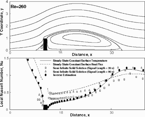
and show the streamline contours and Nusselt number variation for flow past a rib at Reynolds numbers of 160 and 260, respectively. The solution obtained from the inverse calculation is shown by solid circles. The Nusselt number from constant temperature and constant flux boundary condition obtained from direct numerical calculation are shown by solid and dashed lines, respectively. Open symbols have been used to denote the data calculated from the semi-infinite solid approximation. In the inverse calculation, the Nusselt number profile for a flat plate was used as the initial guess for the rib configuration. The agreement between the inverse solution and the pure numerical solution can be seen to be good. The peak in the Nusselt number beyond the rib is seen to be located at the reattachment point of the separation zone, at both the Reynolds numbers. The result from the semi-infinite solid approximation over-predicts the Nusselt number in the recirculation zone and the deviation is higher for a greater signal length.
Figure 8. Streamlines and local Nusselt number as a function of dimensionless distance for convective heat transfer over a ribbed surface; Re = 160.
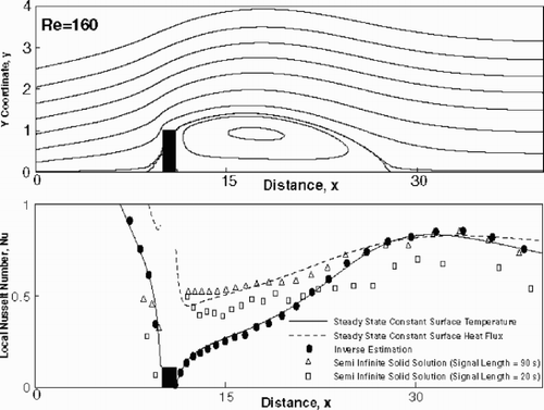
Figure 9. Streamlines and local Nusselt number as a function of dimensionless distance for convective heat transfer over a ribbed surface; Re = 260.
While comparing the inverse solution with the one-dimensional semi-infinite solid solution, it is seen that the latter has a tendency to overestimate Nusselt number in the vicinity of the rib. This can be explained via the restrictive assumption of one-dimensionality of heat conduction in the bakelite sheet. Lin and Wang Citation[11] have explicitly shown in the context of LCT data that the tendency of overestimation is severe in one-dimensional heat conduction models.
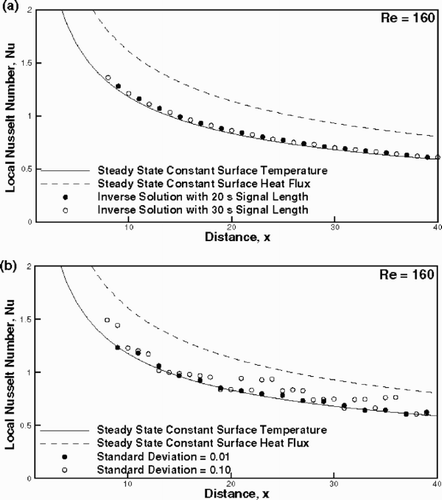
The issue of signal length is relevant to inverse calculations as well. As explained in section 4.1 (Equationequation 10), the algorithm works with a subset of images collected for the entire experiment. Some of the images are required for establishing the convergence of the iterations. In addition, experimental data carry superimposed noise, and it is necessary to assess the sensitivity of the inverse prediction to scatter in the measured data. This study has been conducted as follows. An additional zero mean Gaussian noise is introduced in signals within the first 10 s out of the total of 20 s data. To introduce noise, a zero mean Gaussian random number sequence is generated from a uniform variate using the Box–Muller method Citation[19]. The perturbed temperature is given by:
shows that the predictions of the inverse technique barely change when the signal length increases from 20 to 30 s. This result is important from a computational viewpoint, since a longer signal length indicates a greater amount of CPU time for processing the LCT images. shows that the inverse technique does not amplify noise for σ = 0.01, though noise persists at σ = 0.1. This result sets up the guideline for the quality required in the LCT experiment.
9. Conclusions
An inverse convection technique for local Nusselt number estimation has been presented. The input to the algorithm is a set of of surface temperature distributions in the form of LCT data, during a transient cooling process of the wall from an initially isothermal state. Two geometries, flat plate and one with a surface-mounted rib, have been considered. For the Reynolds numbers studied, the flow fields in both the geometries were found to be steady and two-dimensional. The following conclusions have been arrived at in the present work:
| 1. | The inverse technique is an accurate tool for extracting local variations in Nusselt number from LCT data. On convergence, the estimated Nusselt distribution matches the profile appropriate to the initial thermal boundary condition of the wall. | ||||
| 2. | Within limits, the technique is insensitive to noise in the experimental data. It is also robust with respect to the number of LCT images, and hence the signal length used in the algorithm. | ||||
Nomenclature
References
References
- Beck JV Blackwell G St. Clair CR 1985 Inverse Heat Conduction: Ill-posed Problems New York Wiley
- Ozisik MN Orlande HRB 2000 Inverse Heat Transfer: Fundamentals and Applications New York Taylor and Francis
- Huang , CH and Ozisik , MN . 1992 . Inverse problem of determining unknown wall heat flux in laminar flow through a parallel plate duct . Numerical Heat Transfer, Part A , 21 : 55
- Huang , CH and Chen , WC . 2000 . A three-dimensional inverse forced convection problem in estimating surface heat flux by conjugate gradient method . Int. J. Heat Mass Transfer , 43 : 3171
- Colaco , MJ and Orlande , HRB . 2001 . Inverse forced convection problem of simultaneous estimation of two boundary heat fluxes in irregularly shaped channels . Numerical Heat Transfer, Part A , 39 : 737
- Ireland , PT and Jones , TV . 1987 . Response time of a surface thermometer employing encapsulated thermochromic liquid crystals . J. Phys. , 20 : 1195
- Ireland , PT and Jones , TV . 2000 . Liquid crystal measurements of heat transfer and surface shear stress . Meas. Sci. Technol. , 11 : 969
- Camci , C , Kim , K and Hippensteele , SA . 1992 . A new hue capturing technique for the quantitative interpretation of liquid crystal images used in convective heat transfer studies . ASME J. Turbomachinery , 114 : 765
- Chan , TL , Ashforth-Frost , S and Jambunathan , K . 2001 . Calibrating for viewing angle effect during heat transfer measurements on a curved surface . Int. J. Heat Mass Transfer , 44 : 2209
- Wang , Z , Ireland , PT , Kohler , ST and Chew , JW . 1998 . Heat transfer measurements to the gas turbine cooling passage with inclined ribs . Trans ASME: Journal of Turbomachinery , 120 : 63
- Lin , M and Wang , T . 2002 . A transient liquid crystal method using a 3-d inverse transient conduction scheme . Int. J. Heat Mass Transfer , 45 : 3491
- Ekkad , SV and Han , J-C . 2000 . A transient liquid crystal thermography technique for gas turbine heat transfer measurements . Meas. Sci. Technol. , 11 : 957
- Tariq , A , Singh , K and Panigrahi , PK . 2003 . Flow and heat transfer in a rectangular duct with single-rib and two-ribs mounted on the bottom surface . Journal of Enhanced Heat Transfer , 10 : 177
- Minkowycz WJ Sparrow EM Scheider GE Pletcher RH 1988 Handbook of Numerical Heat Transfer USA J. Wiley & Sons Inc.
- Gartling , DK . 1990 . A test problem for outflow boundary conditions – flow over a backward facing step . International Journal for Numerical Methods in Fluids , 11 : 953
- Leung , CW , Chen , S and Jarney , Y . 2000 . Numerical simulation of laminar forced convection of laminar forced convection in an air-cooled horizontal printed circuit board assembly . Numerical Heat Transfer, Part A , 37 : 373
- Butler , RJ and Baughn , JW . 1996 . The effect of the thermal boundary condition on transient method heat transfer measurements on a flat plate with a laminar boundary layer . ASME J. Heat Transfer , 118 : 831
- von Wolfersdorf , J , Hoecker , R and Sattelmayer , T . 1993 . A hybrid transient step-heating heat transfer measurement technique using heater foils and liquid crystal thermography . Trans. ASME J. Heat Transfer , 115 : 319
- Press WH Tukolsky SA Vetterling WT Flannery BP 2000 Numerical Recipes in FORTRAN India Cambridge University Press
