
Abstract
Portable chainsaws are associated with substantial risk and can cause serious injury to operators, especially during kickback. This paper presents new results from research and analyses conducted regarding the impact between the different properties of wood on this occurrence. In an open area, such differences may include: wood species, humidity, temperature and the facing angle of the wood fibres in relation to the kerf and shape of the wood surface that comes in contact with the tip of the guide bar. This paper investigates chainsaw kickback including the research results on kickback and wood-cutting energy, saw chain speed and the efficiency of the chainsaw engine. It also presents conclusions drawn from the tests that can be useful for chainsaw users, showing the dependencies between the different properties of wood and the risk of injury.
1. Introduction
1.1. State of the art
Portable chainsaws create substantial injury risk [Citation1] particularly for inexperienced users.[Citation2] Each year over 3 million new chainsaws are sold in the USA. The operation of chainsaws results in over 28,000 chainsaw-related injures annually. The most common hazards associated with chainsaws are injuries caused by kickback, pushback and pull-in, but kickback is the most common and poses the greatest hazard.[Citation3] Under Directive 2006/42/EC,[Citation4] these machines are classified in a group that should be examined with the participation of a third party (a notified body) for compliance with essential requirements. Kickback can cause serious injury and is an uncontrolled force that consists of the guide bar suddenly jerking back towards the operator ().
Figure 1. Chainsaw kickback.
Kickback happens in only tenths of a second and occurs when the chain abruptly stops as a link comes into contact with the wood.[Citation5] Standard No. EN ISO 11681–1:2011 [Citation6] requires that combustion chainsaws tested according to Standard No. ISO 9518:1998 [Citation7] have a kickback angle of ϕ ≤ 45° and saw chain mean braking time t ≤ 0.12 s.
Previous publications have examined kickback from standardized fibreboard samples for different chainsaws or chainsaws equipped with different accessories.[Citation8] These studies have shown that only a small portion of the maximum kinetic energy of the engine and cutting assembly is transferred to the chainsaw body, causing it to kick back. The bulk of the energy is used by the chain links cutting kickback samples – mainly related to making a kerf.
Some scientific studies have also covered theoretical analysis and empirical studies on the relationship between wood-cutting efficiency, wood properties and chainsaw characteristics [Citation9] as well as the impact of certain technical parameters of chains on kickback angles.[Citation10]
So far, there have been no known publications analysing the impact of different types of wood on kickback. These properties can vary during most of the work carried out with chainsaws in an open area. It is also worth noting that samples of different wood species differ in density. According to Kubiak and Laurow,[Citation11] the density of beech and oak is 0.71–0.8 g/cm3, and the density of pine and spruce 0.41–0.50 g/cm3. In addition, wood species have different hardness in relation to each other as well as their cross sections.
Thus, undertaking research to analyse the impact of real wood properties on chainsaw kickback is essential in increasing the safety of working with these machines. This topic is also a new contribution to the current knowledge in understanding this dangerous phenomenon, which can also be dependent on variations in wood properties during common tasks carried out with chainsaws in an open area. Better knowledge about wood properties improves chainsaw operators’ skills which should be considered as important prevention measure.[Citation12]
1.2. Research aims and hypotheses
The aim of the study was to determine the effect of the properties of real wood varieties on portable chainsaw kickback as well as to address the reference of standardized kickback tests in terms of the actual worksites of chainsaw operators and existing injury threats.
The research hypothesis was as follows: in order to reduce the risk of chainsaw kickback, it is necessary for the operator to account for the properties of the wood to be cut, which may vary when using a chainsaw in an open area.
2. Testing method
2.1. Test equipment
A stand for testing kickback was designed and built in accordance with Standard No. ISO 9518:1998, and was the principal piece of equipment used for this study (see Dąbrowski [Citation5] for details, ). Other stands were also used, including stands for testing the chainsaw moment of inertia [Citation13] or mechanism start time and saw chain braking,[Citation14] and others described in detail in Dąbrowski.[Citation8]
Figure 2. Principle of the study of chainsaw kickback (horizontal and rotary movement energy) on a test stand.
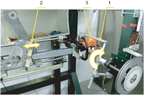
The tests were carried out with: a hygrometer (Tanel, Poland), a digital dynamometer (Metek, Germany) and a climatic test chamber (Heraeus, Germany).
A camera (Fastec, USA) was also used for tracking the movement of the saw chain links on the guide bar during kickback.
2.2. Chainsaws with additional equipment
The chainsaw used in the study was a universal piece of equipment whose basics were engine cubic capacity 56.5 cm3; engine power 3.0 kW; engine rotational speed: idle 2800 rpm, recommended maximum 12,500 rpm, clutch tripping 3700 rpm and recommended guide bar lengths 330–630 mm. Testing of the wood properties was carried out using a semichisel saw and a sprocket nose guide bar with active (cutting) length of 600 mm.[Citation15]
Preliminary tests showed that with this guide bar length, kickback angle values would not exceed 70°, i.e., the maximum value, calculated in accordance with Standard No. ISO 9518:1998 [Citation7] by a computer program.
2.3. Wood test samples
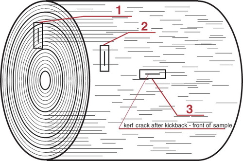
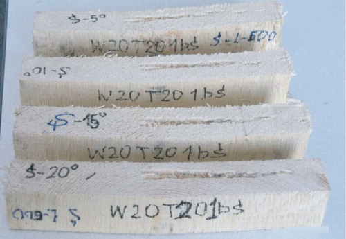
Kickback was tested on 38 × 38 × 250-mm3 wood samples, in accordance with Standard No. ISO 9518:1998,[Citation7] so that they could be mounted on the test stand. These samples had different properties included in previous studies on wood-cutting performance. Tests were conducted on samples of hardwood (oak and beech) and softwood (pine and spruce) cut with a circular saw. The method of collecting kickback samples from logs is shown in .
Figure 3. Method of selecting kickback samples from a wood log to determine the impact of fibre direction in relation to kerf on chainsaw kickback.
Test samples also had different surface shapes () to come in contact with the tip of the guide bar. The comparison covered the kickback impact of flat samples and rounded samples (two radii of curvature).
Figure 4. Dimensions and shape of wood kickback samples used for tests.
2.4. Quantitative estimation of kickback
Reduction in the kinetic energy of the saw chain and the elements of its driving system (as a result of the saw stopping) [Citation8] is defined as the value of maximum (theoretical) energy Ep which can be transferred to the chainsaw during kickback and is described as
(1) where Jp = inertia of the chainsaw, clutch drum and nose sprocket on the guide bar towards the axis of the crankshaft of the engine (kg·m2), Js = inertia of the engine, flywheel and the wheel of the clutch (kg·m2), ωs = angular velocity of the engine before the chainsaw links come into contact with the wood (rad/s) and ωs1 = angular velocity of the engine after the chainsaw links come into contact with the wood, which equals the velocity of the disconnection of the clutch (rad/s).
For analytical reasons, a kickback coefficient (ko) is defined as the ratio of chainsaw kickback energy to the value of maximum kinetic energy reduction by the engine and the cutting assembly; ko was calculated with
(2) where Eo = Wh + Wr = chainsaw kickback energy (J), Wh = horizontal movement energy, Wr = rotary movement energy and Ep = maximum value of reduction in the kinetic energy of the engine and saw chain driving system (J).
The kickback coefficient ko indicates the value of energy absorbed by the wood. The lower its value, the more energy is absorbed by the wood.
Chainsaw kickback energy Eo was calculated according to Standard No. ISO 9518:1998. The maximum rotation angle of the chainsaw (maximum rotary movement energy Wr) in the cradle and maximum horizontal back movement of the carriage with a wood kickback test sample (maximum horizontal movement energy Wh) were considered:
(3) where Wh = horizontal movement energy (J) and Wr = rotary movement energy (J).
Using the camera, the velocity V () of saw chain links moving on the guide bar was calculated:
(4)
(5)
Figure 5. Determining saw moving speed of chain links: (a) horizontal guide bar arrangement; (b) guide bar nose lifting.
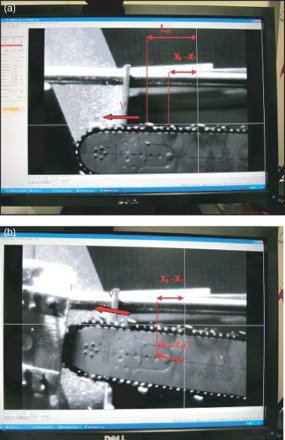
where V = horizontal velocity of links moving on the guide bar (m/s), V′ = velocity of links moving on the guide bar when tilted (m/s), X1 = initial position of the horizontal blade of the cutting link (in pixels), X2 = final position of the horizontal blade of the cutting link (in pixels), n1 = number of the footage first frame, n2 = number of the next frame (n2 = n1 + 5, examined at 0.005-s intervals), N = shooting speed (in frames/s) (1000 frames/s used), ΔA = length corresponding to 1 pixel (m) (calculated based on the distance between the horizontal blades of identical links of the saw chain = left or right), L = the actual length of the pattern (distance between the horizontal blades of identical links of the saw chain) (m) (for semichisel saw L = 0.074 m), Lp = length of the pattern seen on the footage frame (in pixels) and (X2 − X1)′ = travel of the cutting link on the guide bar calculated if the guide bar is not horizontal (tilted), calculated on the basis of the current angle at which the guide bar deviates from the level (at 0.005-s intervals).
3. Tests
3.1. Range and method
Tests were conducted using a chainsaw with a locked brake. Locking the brake required not only securing the brake lever (with tape) to the front handle, but also removing the brake band. This was necessary, because during kickback the brake would often trigger despite the brake lever being secured, which altered the assumed test conditions.
Tests were performed at different angles αp (changes in αp from 0° to 30°, every 5°) (). There were three kickback tests for each angle αp. Horizontal (Wh) and rotary (Wr) movement energy and their mean values were measured and calculated. Three additional tests were performed if the difference between the energy values and the mean energy value was higher than 10%. The test with the maximum kickback energy was used in further studies. The number of tests with different contact angles αp depended on the test results; usually there were three or four tests. This was sufficient to determine the angle αp which caused maximum kickback angle.
Figure 6. Contact of wood test sample with guide bar tip on the kickback test stand.
Tests were performed with chainsaws with a locked chain brake. The method for marking the basic properties (used for identifying and describing the test results) and humidity and temperature of kickback samples is presented in .
Table 1. Test programme for wood samples.
To determine the maximum angle of kickback from samples contacting cylindrical surfaces (with a large radius of R = 160 mm and small radius of r = 80 mm) with the tip of the guide bar, three different variants of this contact were used (Figures ).
Figure 7. Distance of guide bar symmetry axis from symmetry axis of cylindrical surface of round wooden samples.
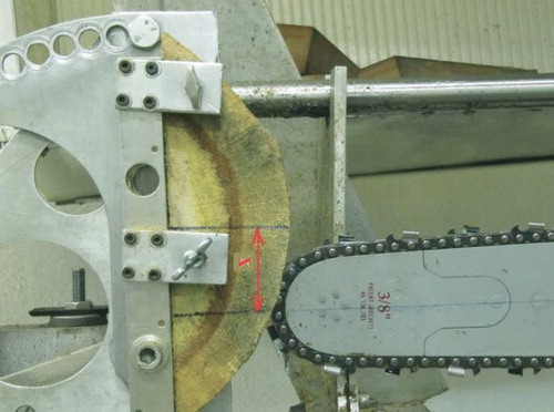
Each of these variants had different x distance of the guide bar symmetry axis from the symmetry axis of the cylindrical surface of the rounded wood samples 0, 0.5 R (r), 0.7 R (r). These tests were carried out on samples of spruce, pine, oak and beech with a temperature of 20 °C and humidity of 20%.
To analyse woodworking during chainsaw kickback, we measured specific cutting resistance for wood samples used in the tests (pine, spruce, oak and beech). Wood-cutting-specific resistance tests were conducted for four species of wood and three different kerf arrangements (in line with the arrangement during chainsaw kickback) in relation to the direction of the wood fibres ().
3.2. Determination of kickback angle accuracy
The calculated final value of the kickback angle uncertainty, taking into account the uncertainty of tests on auxiliary stands, was ±2°.[Citation4] The stands included test stands for: chainsaw moment of inertia,[Citation13] mechanism start time, saw chain braking [Citation14] and others described in detail in Dąbrowski.[Citation8]
4. Results
4.1. Testing the impact of wood properties on kickback
In accordance with different variants (), for testing the impact of wood properties on chainsaw kickback, samples were selected to differ in
species and direction of fibres in relation to the direction of the saw chain cutting blade movement (kerf arrangement);
humidity;
temperature;
shape of the surface in contact with the tip of the guide bar ().
Table 2. Cutting energy (work) during chainsaw kickback from selected wood samples.
4.1.1. Wood species and kerf arrangement
The tests were performed on softwood samples, i.e., pine and spruce; and on hardwood samples, i.e., beech and oak ().
Figure 8. Kerfs in flat spruce samples.
For each species of wood, three kerf arrangements () were adopted ().
Figure 9. Dependence of kickback angle on kerf arrangement for four wood species.
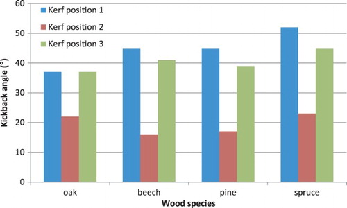
The tests yielded large differences in the angles of chainsaw kickback, ranging from 15° to 52°. The greatest kickback angles occurred for spruce samples and the lowest for oak samples. For beech and pine samples, comparable chainsaw kickback angles were obtained. When comparing the results for the various kerf arrangements, it can be concluded that the maximum kickback angles (regardless of the type of wood) are present for kerf arrangement 1. By far the smallest kickback angles are seen in arrangement 2.
4.1.2. Humidity of wood samples
An investigation of the effect of wood humidity on chainsaw kickback () was carried out at a temperature of 20 °C on spruce, oak and pine samples. In order to obtain the specific moisture content in the wood, samples were conditioned in a climate chamber, but in order to obtain a moisture content of ≥60%, they also had to be placed in vessels with water. Even so, as a result of these measures, the maximum humidity of 70% was only obtained for the spruce samples.
Figure 10. Dependence of kickback angle on wood humidity for different wood species and kerf arrangement.
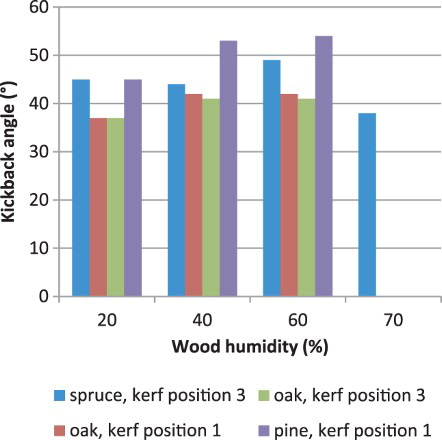
The results show that within the humidity range of 20–60%, the increase of this parameter caused an increase in the chainsaw kickback angle.
4.1.3. Temperature of wood samples
These tests () were carried out on spruce, pine and oak samples, at a temperature range of −10 to 20 °C.
Figure 11. Dependence of kickback angle on wood temperature for different wood species and kerf arrangement.
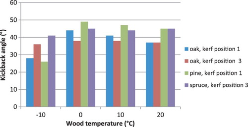
In order to maintain the below freezing temperature of the samples tested, in addition to the climate chamber, a freezer located directly next to the test stand was also used. In this test, subzero sample temperatures (−10 °C) resulted in small kickback angles, and the greatest kickback angles occurred when sample temperature rose up to 0 °C.
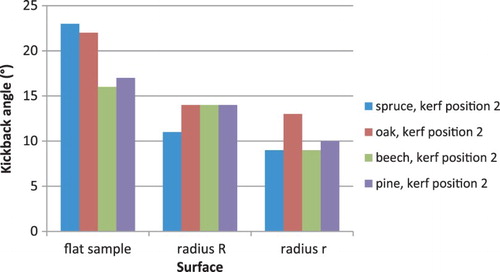
4.1.4. Surface shapes of wood samples
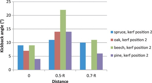
Each of the sample variants had different x distance of the guide bar symmetry axis from the symmetry axis of the cylindrical surface of the rounded wood samples 0, 0.5 R (r), 0.7 R (r). These tests were carried out on samples of spruce, pine, oak and beech at a temperature of 20 °C and humidity of 20%. All wood samples with kerf arrangement 2 () with cylindrical surfaces had smaller kickback angles as compared to flat samples, however, the samples with smaller cylindrical surface radii had smaller kickback angles as compared with the samples with larger cylindrical surface radii ().
Figure 12. Dependence of kickback angle on the shape of the surface of wood samples for different wood species and kerf arrangement.
Reduction in the radius of the sample cylindrical surface was followed by a reduction of the maximum kickback angle as compared to flat samples. shows the change in the kickback angle for each sample, with cylindrical surface with radius R when changing the x distance of the guide bar axis from the symmetry axis of the sample cylindrical surface (). The greatest kickback angles were obtained for the test variant where the x distance was 0.5 R.
Figure 13. Dependence of kickback angle on distance of guide bar symmetry axis from symmetry axis of cylindrical surface of round wooden samples.
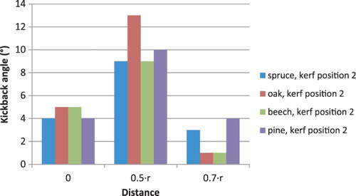
shows the change of the kickback angle for each sample, with cylindrical surface with radius r when changing the x distance of the guide bar axis from the symmetry axis of the sample cylindrical surface. The greatest kickback angles were also obtained for the test variant where the x distance was 0.5 R.
Figure 14. Dependence of kickback angle on distance of guide bar symmetry axis from symmetry axis of cylindrical surface of round wooden samples.
4.2. Testing the movement of the saw chain links on the guide bar during kickback
In order to verify the change in the saw chain velocity during chainsaw kickback from wood samples, a high-speed camera was used to analyse the saw chain movement. Kickback was observed until the guide bar left the kickback sample (which could be seen on the computer screen used to analyse the process using a special application, frame-by-frame camera footage). The camera helped to analyse the movement of the saw chain during kickback at contact angles αp causing maximum and minimum kickback angle for a given wood species and kerf arrangement, i.e.,
spruce (), at contact angles αp () of 5° and 10° (kickback angles 18° and 52°, respectively): sample W20T201bś;
pine (), at contact angles αp of 15° and 20° (kickback angles 17° and 5°, respectively): sample W20T202bs;
beech (), at contact angles αp of 10° and 20° (kickback angles 16° and 6°, respectively): sample W20T202ab.
Figure 15. Course of saw chain speed during kickback from spruce samples. Note: Kerf arrangement 1, marking: spruce 1. Minimum linear (rotary) speeds are 10.1 m/s (486 rad/s) and 7.7 m/s (371 rad/s) for contact angles αp of 5° and 10°, respectively.
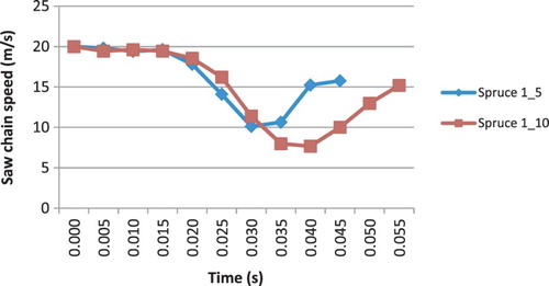
Figure 16. Course of saw chain speed during kickback from pine samples.
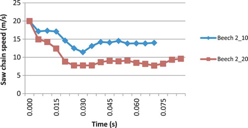
Figure 17. Course of saw chain speed during kickback from beech samples.
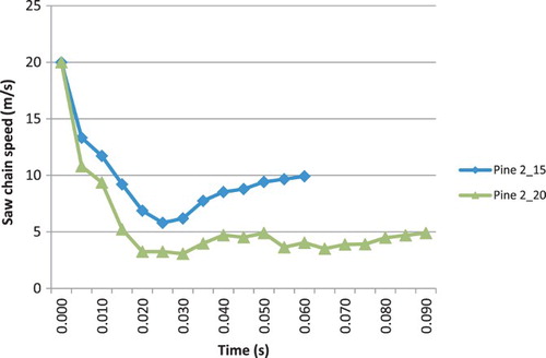
Tests showed that the saw chain contact time with the wood did not exceed 0.1 s with the kickback duration not longer than 0.27 s. Among the samples tested, the shortest contact time was recorded for spruce samples. The initial velocity of the saw chain moving on the guide bar of 20 m/s (at engine velocity of 9000 rpm) decreased to 3 m/s for pine samples, while for spruce and beech samples to 7 m/s, though for spruce samples, deceleration was more sudden and short-lived.
4.3. Testing wood sample cutting resistance
Cutting resistance, which depends on the direction of the kerf, had the following values:
for pine samples: 24.13–29.19 MPa;
for oak samples: 40.49–39.23 MPa;
for beech samples: 54.77–45.01 MPa;
for spruce samples: 23.75–16.02 MPa.
Regardless of the species of wood tested, cutting resistance was greatest for kerf arrangement 2 (), which had the smallest kickback angles.
The volume and length of kerf in the tested samples were also measured. The measurements did not reveal any significant difference in kerf volume between the samples that yielded extreme values of kickback angles (at various angles αp), e.g.,
spruce (samples W20T201bś), at contact angles αp of 5° and 10° (kickback angles 18° and 52°, respectively), kerf volume and length were 1800 and 1700 mm3, and 74 and 86 mm, respectively;
beech (samples W20T202ab), at contact angles αp of 10° and 20° (kickback angles 16° and 6°, respectively), kerf volume and length were 1200 and 1400 mm3, and 48 and 44 mm, respectively.
4.4. Testing kickback energy
The study used a theoretical model of chainsaw kickback [Citation8] given by equation (1), which specifies the maximum reduction of the kinetic energy of the engine and saw chain drive system (including the saw chain) during kickback, passed onto wood cutting and chainsaw kickback.
Tests with the camera showed that the saw chain velocity was not reduced to zero but rather to a given value of ωp. Then the modified formula of maximum chainsaw energy reduction can be expressed as
(6) where ωp = reduced angular velocity of the saw chain, determined on the basis of camera tests, and Ep1 = maximum reduction in chainsaw energy with regard to the actual reduced rotational speed of the saw chain ωp.
The specific resistance tests for chainsaw cutting of wood samples used in the tests (pine, spruce, oak and beech) helped to estimate the cutting energy (work) that is lost (dissipated) by the chainsaw when making a kerf, and the impact of the work value on the diversity of the kickback angle. Sample woodworking volumes are shown in .
Therefore, the energy Ep2, which can be transferred to the chainsaw body (reduced by the cutting energy Eskraw), causing kickback, should be equal to
(7) and the kickback coefficient ko2 can be calculated from
(8)
Taking into account the increased value of chainsaw cutting energy, given the 50% efficiency of its engine,[Citation15] the kickback coefficient ko3 can also be calculated from
(9) where Ep3 = Ep1 – 2·Eskraw (J).
shows energy values Ep, Ep1, Ep2 and Ep3 for the samples tested and the calculated kickback values ko, ko1, ko2 and ko3.
Table 3. Chainsaw kickback energies and angles.
5. Discussion
5.1. Impact of wood properties on kickback
5.1.1. Wood species and kerf setting
Kickback angles were greatest during testing the spruce samples. Kickback kerfs created in these samples were not homogeneous. The kerfs showed jagged wood fibres, which prove the existence of heavy resistance and rapid saw chain braking during kickback. However, for other types of wood, hardness did not clearly have a varied impact on chainsaw kickback.
When comparing the results for the various kerf arrangements, it can be concluded that the greatest kickback angles (regardless of the type of wood) were present for kerf arrangement 1, with the smallest one for kerf arrangement 2. In that case, the fibre arrangement determines the saw chain braking or cutting processes (losing kickback energy for cutting).
5.1.2. Humidity of wood samples
The results show that within a humidity range of 20–60%, an increase in this parameter caused an increase in the chainsaw kickback angle. During kickback in wet wood, saw chain links tended to catch the wood and decelerate. Dissipation of kickback energy from the wood-cutting process occurred to a lesser extent. For spruce samples, 60% humidity resulted in softening and a decrease in kickback angle.
5.1.3. Temperature of wood samples
Regardless of the type of wood, the kickback angles were smallest when the wood was frozen. Low temperature makes fibre structure lose significance in relation to kickback. In this way, wood cutting has a significant impact on dissipation of kickback energy.
With wood defrosting to 0 °C, however, the kickback angle increases, which is associated with an increase in wood moisture content and processes of chainsaw rapid deceleration (wood catching), with less participation of kickback energy dissipation in the cutting process.
5.1.4. Surface shapes of wood samples
The tests showed that as the surface radius in contact with the guide bar tip increases, so does the kickback angle. The tests were performed with kerf arrangement 2, i.e., the same as for cross-cutting wood where the tip of the guide bar may come in contact with a cylindrical surface.
The smaller kickback angle from cylindrical surface samples (as compared to flat samples) indicates a more significant participation in the wood-cutting process for guide bar positions 0.5 and 0.7 R (r); short-lived saw chain contact with the wood for position 0 R (r) did not cause a slowdown.
5.2. Analysis of saw chain link movement on the guide bar and wood-cutting resistance
By analysing the course of the saw chain velocity during chainsaw kickback from various wood samples, conclusions can be drawn about the sample cutting process during kickback. Rapid saw chain deceleration (as in the case of spruce samples) proves that the saw chain does not do heavy cutting work in the kerf. It is more of a braking and wood catching process. The more rapid the braking that occurs, the greater the kickback angle. For a relatively long period during saw chain deceleration, it can be concluded that the cutting process is present. In this case, the greater the reduction, the greater the energy dissipated for cutting and the smaller the kickback angle.
The results of the calculations of kerf cutting energy (work) done by the chainsaw indicate that this energy affects the kickback angle. For all analysed cases, greater kerf volume, equivalent to greater cutting energy, was associated with a decrease in the kickback angle. Therefore, an increase in chainsaw energy dissipated for kerf cutting reduces the kickback angle.
Taking into account the actual deceleration of the saw chain and kerf cutting work, in the analysed cases, the maximum chainsaw energy Ep = 465.9 J, which in theory could be potentially transferred to the chainsaw body (causing kickback), is largely dissipated. Also, taking into account the increased value of the chainsaw cutting energy in relation to the 50% efficiency of its engine and the fact that the greatest kickback energy is approximately 10% of the chainsaw energy Ep (i.e., about 40 J), in some cases, the energy balance is closed with only 20% of the energy dissipated during kickback (except for cutting energy) which, we may assume, is lost for saw chain friction in the wood or against the guide bar,[Citation16,Citation17] or dissipated in chainsaw mechanisms.
6. Practical conclusions for chainsaw operators
6.1. Impact of wood properties and chainsaw kickback
When chainsaw kickback from flat samples of different types of wood (beech, oak, pine and spruce) was tested, there were differences in the angles of chainsaw kickback of 15°–52°.
However, due to the complexity of the saw chain braking process that depends on, e.g., wood deformation by a chip thickness limiter, and cutting resistance, the tests did not show a simple relation between wood species (hardness) and kickback angle. Therefore, the hardness of the wood is not a factor that significantly affects kickback. However, kickback angles and risk are greatest for spruce samples, in which kerfs formed after kickback have jagged wood fibres, which indicates wood catching and rapid saw chain braking during kickback. The smallest angles were obtained for oak samples with kerfs with a uniform surface, which proves the occurrence of the cutting process.
When testing kickback from flat wood samples, kickback angles depended on kerf arrangement in relation to the direction of fibres, with the most preferred kerf arrangement in terms of risk reduction being the one used for wood log cross-cutting.
Within the humidity range of the samples of 20–60%, an increase in this parameter caused an increase in the chainsaw kickback angle, thereby increasing operator risk. Saw chains had a tendency to catch wood and brake rapidly, which could be seen from the post-kickback kerfs made in the wet wood samples.
Regardless of the type of wood, kickback angles were smallest for frozen samples. In this case, the fibre structure did not have such a significant effect on kickback. Kerfs left in the samples showed a uniform process of wood cutting. This indicates that working with chainsaws during winter poses the lowest risk. When defrosting wood to 0 °C, kickback angles increased along with wood humidity.
The tests conducted with kerf arrangement for wood cross-cutting showed that as the radius of the surface in contact with the guide bar tip increased, so did the kickback angle. The smaller angle of kickback from the cylindrical surface samples (as compared to flat samples) indicates a more significant participation of the wood-cutting process and kickback energy dissipation in this case. For cylindrical surfaces, the kickback angle depended on the position of the guide bar symmetry axis in relation to the axis of the cylindrical surface of the sample.
6.2. Saw chain movement and guide bar
By analysing the course of saw chain velocity with a camera, conclusions can be drawn about the sample cutting process during kickback. Rapid and short-term deceleration of the saw chain (like for spruce samples) resulted in lower energy dissipation for cutting, and a greater increase in the kickback angle. The relatively lengthy deceleration period of the saw chain means greater energy dissipation for cutting, and a lower kickback angle, as confirmed by the test results.
By examining chainsaw kickback with a camera, it was possible to verify empirically the theoretical kickback model for saw chain movement during kickback. Knowing the changes in the saw chain velocity at different stages of kickback, it was possible to analyse more accurately the impact of various factors on the course of kickback. In previous theoretical studies, the worst-case scenario was assumed, i.e., that the saw chain after contact with wood reduces the speed on the guide bar to zero. Practical studies have shown that the saw chain assumes such state only when the chainsaw has an efficient brake that triggers automatically as a result of the angular acceleration of the guide bar tip. By examining kickback with a camera, it was possible to determine a modified (lower) chainsaw energy that can be transferred for the kickback.
The specific wood-cutting resistance tested varied depending on the type of wood and kerf arrangement. The greatest cutting resistance occurred for kerf arrangement of wood cross-cutting, which also had the smallest kickback angles. During tests, larger kerf volume (equivalent to greater cutting energy) was associated with a decrease in the kickback angle. Based on kerf volume measurements and specific cutting resistance, it was possible to define cutting operation and thus dissipation of potential chainsaw kickback energy as a result of cutting.
Having the ability to determine the saw chain velocity and kerf cutting work as well as the efficiency of the chainsaw engine, it was possible to make the maximum energy value of the chainsaw, which theoretically may cause kickback, more realistic, and thus better assess the risk associated with this phenomenon. This is particularly important in countries like Poland, where chainsaws are still widely used for logging.[Citation18]
6.3. Saw chains and users’ manuals
The following conclusions could be used in users’ manuals.
Extra attention is necessary when spruce wood logs are cut because of the large kickback angle caused by the saw chain cutting links catching wood and sudden slowing down.
The risk of kickback is lowest when wood is cut across log fibres; it increases when wood is cut along wood log fibres.
Cutting frozen wood logs is safest, because the differentiation in their structure does not affect the kickback phenomenon so much.
Extra attention is necessary when wood with elevated humidity is cut because of an increased risk of kickback.
It is very important to maintain chain brake efficiency. The brake not only stops the chain (at kickback) but it also decreases the kickback angle by dispersing kickback energy in the chainsaw (chain brake) mechanisms.
The greater the diameter of wood logs cut across fibres, the higher the risk of kickback. The risk of kickback is greatest when guide bar tips are in contact with a flat wood surface.
Disclosure statement
No potential conflict of interest was reported by the author.
References
- Schyma C, Albalooshi Y, Madea B. Extended suicide by use of a chain saw. Forensic Sci Int. 2013;228(1–3):e16–e19.
- Malinowska-Borowska J, Zieliński G. Coupling forces exerted on chain saws by inexperienced tree fellers. Int J Ind Ergon. 2013;43(4):283–287.
- Koehler SA, Luckasevic TM, Rozin L, et al. Death by chainsaw: fatal kickback injuries to the neck. J Forensic Sci. 2004;49(2):345–350.
- Directive 2006/42/EC of the European Parliament and of the Council of 17 May 2006 on machinery. OJ. 2006;L157:24–84 [cited 2015 Sep 7]. Available from: http://eur-lex.europa.eu/LexUriServ/LexUriServ.do?uri=OJ:L:2006:157:0024:0086:en:PDF
- Dąbrowski A. National Programme ‘Improvement of safety and work conditions’ Task 4.R.16 Determining of kickback hazards by cutting of wood with different characteristics for accidents prevention [unpublished report]. Warszawa: CIOP-PIB; 2010. Polish.
- European Committee for Standardization (CEN). Machinery for forestry – Portable chain-saw safety requirements and testing – Part 1: Chainsaws for forest service (Standard No. EN ISO 11681–1:2011). Brussels: CEN; 2011.
- International Organization for Standardization (ISO). Forestry machinery – Portable chain-saws – Kickback test (standard No. ISO 9518:1998). Geneva: ISO; 1998.
- Dąbrowski A. Reducing kickback of portable combustion chain saws and related injury risks: laboratory tests and deductions. Int J Occup Saf Ergon. 2012;18(3):399–417. doi:10.1080/10803548.2012.11076943
- Maciak A. Influence of saw chain cutters characteristics on woodworking efficiency [doctoral dissertation]. Warszawa: Faculty of Production Engineering, Warsaw University of Life Sciences SGGW; 2001. Polish.
- Więsik J. Sposoby zmniejszania energii i eliminowania odbicia współczesnych pilarek łańcuchowych [Ways of eliminating or reducing kickback in modern chain saws]. Przeg Techn Roln Leśn. 2001;(10):18–22.
- Kubiak M, Laurow Z. Surowiec drzewny [Wood material]. Warszawa: SGGW; 1994.
- Lindroos O, Burström L. Accident rates and types among self-employed private forest owners. Accid Anal Prev. 2010;42(6):1729–1735.
- American National Standards Institute (ANSI). Safety requirements for gasoline powered chain saws (Standard No. ANSI B175.1:2000). Washington, DC: ANSI; 2000.
- International Organization for Standardization (ISO). Portable chain-saws – Chain brake performance (Standard No. ISO 6535:2008). Geneva: ISO; 2008.
- OREGON. Frequently asked question [cited 2013 Dec 30]. Available from: http://www.oregonproducts.com/pro/service/faq.htm
- Gendek A. Wpływ parametrów sprzęgła na wydajność skrawania drewna pilarką spalinową [Influence of clutch parameters on combustion chain saw woodworking efficiency] [doctoral dissertation]. Warszawa: SGGW; 2005.
- Gendek A, Oktabiński P. Engine power losses on resistance of chain saw motion over the guide. Annals of Warsaw University of Life Sciences – SGGW. Agriculture No. 60 (Agricultural and Forest Engineering); 2012:111–117 [cited 2015 Sep 7]. Available from: http://annals-wuls.sggw.pl/files/files/agriculture/afe2012no60art11.pdf
- Zychowicz W. Analysis of age and size structure of chain saws used in the selected regions of Poland. Annals of Warsaw University of Life Sciences – SGGW. Agriculture No. 53 (Agricultural and Forest Engineering); 2009:55–61 [cited 2015 Sep 7]. Available from: http://annals-wuls.sggw.pl/files/files/afe2009no53art08pub.pdf