?Mathematical formulae have been encoded as MathML and are displayed in this HTML version using MathJax in order to improve their display. Uncheck the box to turn MathJax off. This feature requires Javascript. Click on a formula to zoom.
Abstract
Saw kickback can cause fatal injuries, but only woodcutting saws have regulations and assessment methodologies for kickback. These regulations do not apply to abrasive cutting saws, as their cutting mechanism and dominant kickback mode differ from those of woodcutting saws. This work combines theoretical and experimental tools to investigate abrasive saw kickback. A theoretical model based on frictional engagement during a pinch-based kickback event is shown to predict resultant kickback energy in good agreement with experimental measurements. These measurements were obtained using a specialized machine that generates pinch-based kickback events and measures resultant kickback energy. Upon validating the model, two representative saws, a circular cutoff saw and a chainsaw, were tested using the prototype machine to evaluate their comparative kickback risk. This work demonstrates that pinch-based kickback is a potential safety risk for abrasive cutting saw operators and provides a testing machine design and analytical framework for evaluating this risk.
1 Introduction
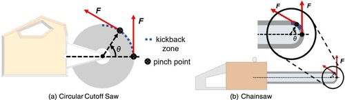
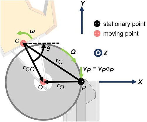
Operating power tools carries inherent risk, but some hazards are more dangerous than others. Of the hazards associated with operating woodcutting chainsaws, kickback is the most common and dangerous [Citation1–3]. Although the documentation of this hazard refers to incidents involving woodcutting chainsaws in forestry applications, kickback also causes fatal injuries on construction sites, where the use of abrasive saws for metal and concrete/masonry cutting is more prominent. While woodcutting and abrasive saws have different cutting mechanisms, as illustrated in Figure , operators of both types of saws can experience kickback. Kickback is defined for the purpose of this study as ‘a sudden, unexpected reaction occurring on the upper portion of the guide bar nose causing the guide bar to be driven up and back toward the operator’, as noted by the Chain Saw Manufacturers’ Association [Citation4]. This ‘upper portion’ can be defined as the kickback zone, and it is illustrated in Figure . While this definition refers specifically to kickback for chainsaws, it will also be used here to refer to a similar reaction for a circular cutoff saw.
Figure 1. Visualization of woodcutting (a, c) and abrasive (b, d) cutting elements, as seen on chains (a, b) and blades (c, d). The woodcutting elements have teeth that cut into the work material, while the abrasive elements are embedded with a hard material (such as diamond) to shear through the work material. Note: The full color version of this figure is available online.
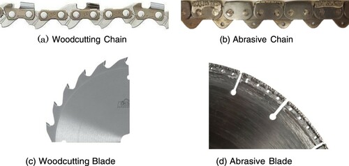
Figure 2. Illustration of the kickback zone on a circular cutoff saw (a) and a chainsaw (b). The kickback zone is notably larger on the circular cutoff saw due to the larger blade diameter. Note: The full color version of this figure is available online. θ = angle between rCO and the x axis; F = force vector; rCO is the vector from the center of mass of the saw to the center of rotation of the cutting element. Labels in (a) also apply to (b).
This kickback phenomenon is well studied for woodcutting saws due to a US Consumer Product Safety Commission push to regulate woodcutting chainsaws to reduce the hazard of kickback [Citation5]. The subsequent work includes the construction of kickback test machines for measuring the kickback energy of these woodcutting chainsaws [Citation1,Citation6], simulated operator responses to the occurrence of kickback [Citation2] and brake systems for protecting operators from the danger of kickback [Citation3]. Although an increase in the number of chainsaw-related injuries initiated extensive investigation into reducing woodcutting saw kickback [Citation3,Citation5], the resulting measurement techniques and safeguarding methods do not apply to abrasive saws. However, a similar mandate has not been made for further understanding abrasive saw kickback and how it differs from woodcutting saw kickback.
For abrasive saws, dangerous kickback most frequently occurs on construction sites during pipe-cutting operations, particularly when the pipe is in an excavated trench. However, when abrasive saws were tested in a machine analogous to a woodcutting saw kickback machine described by ANSI Standard No. B175.1-2012 [Citation6], similar levels of kickback were not observed by Wu [Citation7], despite reports of kickback in the field. A recent study by Yue [Citation8] theorized that this result is due to abrasive saws primarily experiencing a different mode of kickback whereby the cutting element is pinched in the kerf of the cut, rather than being frontally engaged by the workpiece. To investigate abrasive saw kickback, a kinetics model was developed which treats the abrasive cutting engagement as a sudden frictional engagement. This model predicts the resultant motion of the saw, given assumed engagement parameters, allowing for a prediction of the resultant energy transferred to the saw's motion during a kickback event.
A variety of saws are used on construction sites, but they can generally be divided into two main categories: chainsaws and circular cutoff saws. Circular cutoff saws have a large-diameter blade that spins on a shaft in stationary bearings. Chainsaws have a chain that moves around a stationary saw bar, which has a small-diameter semicircle at the nose. For this study, two representative gas-powered saws – one circular cutoff saw (Stihl TS420; Stihl USA, USA) and one chainsaw (ICS 695XL; Blount International, USA) – were used. Additionally, an electric circular cutoff saw (ECCS) was used for initial tuning of the physics model and validation of the machine's data collection. This approach is similar to that taken by Arnold and Parmigiani [Citation9], using electric and gas-powered saws and, subsequently, comparing data.
After Wu [Citation7] observed and Yue [Citation8] confirmed that the dominant kickback mode for abrasive saws is different from that of woodcutting saws, it was necessary to design a new test machine which could controllably and repeatedly produce pinch-based kickback. This machine would need to measure both the rotational and linear kinetic energy of the saw after the kickback to provide data that could be integrated into existing standards relating saw energy levels to kickback safety [Citation6]. This work thus investigates a potential cause of kickback for abrasive power saws on work sites and presents an analytical model of and design for a reliable machine for measuring the kickback risk of these saws that validates the theory.
This manuscript is organized as follows. First, the development of the kickback model and key equations are presented. Next, the design of the test machine is discussed alongside the basic test procedure. Subsequently, test results demonstrating the validity of the of the model and utility test machine are provided. Finally, the test results using the representative gas-powered circular cutoff saw and chainsaw are provided and compared.
2 Methodology
2.1 Model
The kickback phenomenon is modeled by applying a frictional contact force on the saw at a pinch point that is fixed in space. The saw is allowed to rotate and translate in the plane of the blade such that, as the system evolves, the saw blade moves through the pinch point. We restrict the analysis to consider only in-plane motion following observations that confirm the out-of-plane motion is negligible. Boundary conditions determine geometrically when the saw has separated from the pincher, at which point rigid body motion is used to calculate the maximum linear and rotational kinetic energies of the saw.
2.1.1 Definitions
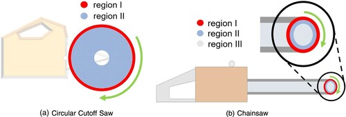
A saw consists of a combination of two rigid bodies: the saw body and the spinning cutting device (blade or chain). For the chainsaw, only the chain moves independently while the enclosed saw bar moves rigidly with the rest of the saw. In the model, the chainsaw cutting blade is treated as a circular ring spinning around the nose sprocket, and the rest of the saw bar region, including the area inside the ring, is treated as part of the saw body. The cutting blade has two regions: the abrasive and non-abrasive parts of the blade. Each of these regions is assigned its own effective coefficient of friction. These regions are illustrated in Figure .
Figure 3. Different regions of a saw cutting blade that can be engaged during kickback: (a) circular cutoff saw and (b) chainsaw. The chainsaw has an additional third region that moves with the saw body. Note: The full color version of this figure is available online.
A diagram illustrating the key vector definitions in the derivation of the kickback model is shown in Figure . The abrasive engagement force is treated as linear friction acting on both sides of the cutting element at point P. Thus, the force is evaluated as the product of an effective coefficient of friction and the normal force of the pinch as:
Figure 4. Labeled diagram showing the vectors used in the model. Note: The full color version of this figure is available online. θ = angle between rCO and the x axis; Ω = angular velocity of the cutting element; ω = angular velocity of the saw; C = center of mass of the saw; eP = unit vector pointing in the direction of the motion of the spinning blade relative to the fixed work material at the pinch point; O = center of rotation of the cutting element; P = pinch engagement point; rC = vector from P to C; rCO = vector from C to O; rO = vector from P to O; vP = linear velocity of the cutting element at point P.
2.1.2 Simplifications
Each saw can be represented as two coupled bodies, the main saw body and the moving cutting element. Because the exact coupling torque is not known for each saw and is complex and difficult to measure, some simplifications are made to model the system. First, since the coupling torque between the bodies is not known, the change in the speed of the cutting blade throughout the kickback cannot be calculated. However, the −Ω × rO term in Equation (2) dominates vP for the majority of a kickback event, even when Ω slows down considerably. Thus, the direction of the force, −eP, does not change significantly when the cutting blade speed changes. To simplify the calculation of vP, a constant value is used for Ω. Note that, since Ω is assumed constant, complete stopping of the blade, which may be observed in extreme pinching scenarios, cannot be captured by this model.
Second, it is desirable to simplify the system into a single rigid body for analysis to remove the need to calculate the coupling torque. Two separate approaches are used to create two models for the system, defined as Model 1 and Model 2, which are illustrated in Figure .
Figure 5. Two formulations resulting in Model 1 and Model 2. (a) For Model 1, the entire saw body and cutting blade system is treated as rigidly connected. (b) For Model 2, the cutting blade is treated as a separate rigid body connected by a pinned joint at O that is assumed to have a negligible mass relative to the saw body. Note: The full color version of this figure is available online. C = center of mass of the saw; F = force vector; I = moment of inertia of the saw; M = mass of the saw body; m = mass of the cutting blade; O = center of rotation of the cutting element; rC = vector from P to C; rCO = vector from C to O.
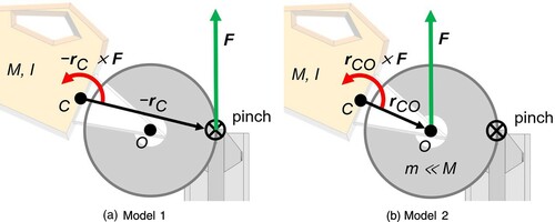
The first simplification, referred to as Model 1, treats the two bodies as one combined rigid body. In this case, kickback force applied on the cutting blade creates a linear force and a torque on the body, resulting in the equations of motion seen in Equations (5) and (6):
(5)
(5)
(6)
(6)
where M = mass of the saw body; rC = vector from P to C; F = force vector; I = moment of inertia of the saw; θ = angle between rCO and the x axis; two superimposed dots/double over dot = two differentiations with respect to time.
The second simplification, referred to as Model 2, treats the cutting blade as a second rigid body connected to the saw body by a pinned joint at O. The cutting blade is assumed to have a negligible mass relative to the saw body. In this case, the force applied to the blade during kickback through the pinch is transmitted to the saw body through the center of rotation of the cutting blade, O. Because the mass of the cutting blade is negligible, the full kickback force is seen by the saw body and is in the same direction as it would be on the cutting blade. In this case, the resulting equations of motions are slightly different, as seen in Equations (7) and (8):
(7)
(7)
(8)
(8)
where M = mass of the saw body; rC = vector from P to C; F = force vector; I = moment of inertia of the saw; θ = angle between rCO and the x axis; rCO = vector from C to O; two superimposed dots/double over dot = two differentiations with respect to time.
Unlike Model 1, where the torque is based on the distance from the center of mass to the pinch point rC, in Model 2 the torque is based only on the distance from the saw center of mass to the center of the cutting blade, rCO. In both models, the same linear force is seen by the center of mass of the system, so the equation based on linear momentum (i.e., Equations (5) and (7)) does not change between them, and it is correct, in general, for the two body system.
The sets of Equations (5) and (6) and Equations (7) and (8) are independently numerically integrated with a MATLAB version R2018b solver to determine the evolution of the system and predict the theoretical bounds of the energy levels of the kickback event. The initial position and velocity of the saw body are sufficient initial conditions and are chosen to match the experiments.
The model has one tuning parameter, friction (µ), in addition to the measured parameters. This parameter is tuned since the cutting force is not well characterized for different materials at high surface speeds and pressures. Consequently, µ is used to fit curves to data sets. It is found that as µ is varied, Model 1 always predicts lower linear kinetic energy and higher rotational kinetic energy than Model 2, providing a pair of windows to fit experimental linear kinetic energy and rotational kinetic energy. The values used for µ between each region of the saw, as illustrated in Figure , and the work material are 0.3 for Region I and 0 for Regions II and III. These values are used for modeling all of the saws tested under all test conditions.
2.2 Test machine
A new type of kickback machine was designed, built and tested to evaluate pinch-based kickback. This machine has three major components: a floating-center, five-bar linkage pneumatic piston actuated pincher that can apply a variable pinch force to the saw's cutting blade, producing kickback; a motion capture harness, which allows for translation and rotation of the saw during kickback; a positioning system, which positions the saw relative to the pincher prior to initiating kickback.
2.2.1 Motion capture harness
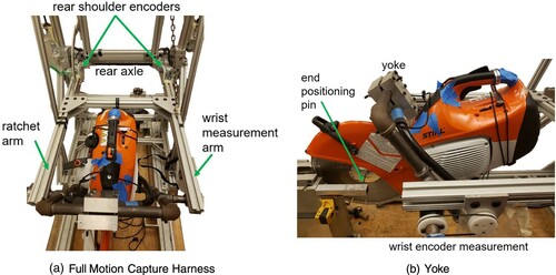
The motion capture harness comprises a pair of horizontal arms that hold the saw at their extremity, as seen in Figure . These arms can rotate about a fixed rear axle at their other extremity, allowing for translation of the saw's center of mass. The arms are sized such that this translation of the center of mass of the saw during engagement is approximately linear by a small angle approximation. Additionally, the arms are horizontal at the beginning of each kickback event such that the saw's initial translational motion is constrained to be entirely in the vertical direction. The saw itself is mounted in a yoke with a rotary axle oriented perpendicular to the cutting plane and aligned with the saw's center of mass, allowing for free rigid body rotation. Rotary encoders at both joints measure the rotational and translational position of the saw throughout kickback. The arms holding the saw yoke are shown in in Figure a, and a side view of the mounted saw yoke is shown in b.
Figure 6. Motion capture harness used to hold the saw and measure the linear and rotational kinetic energy of the saw during the kickback event: (a) arms holding the saw yoke and (b) side view of the mounted saw yoke. Note: The full color version of this figure is available online.
Although the majority of the energy in kickback is due to rotational motion, a linear degree of freedom allows for a more realistic trajectory of the saw during engagement, and kickback engagement changes when the saw's center of mass is allowed to move. Additionally, while the woodcutting saw kickback machine uses a horizontal degree of freedom [Citation6], this linear degree of freedom was chosen to be vertical, as the kickback force was hypothesized to be primarily vertical for dangerous kickback. The woodcutting saw kickback machine uses a horizontal degree of freedom in order to reuse the mechanism that drives the coupon into the saw [Citation10]; since the pinching mechanism used in this machine remains stationary, the direction of the linear degree of freedom can be changed.
2.2.2 Positioning system
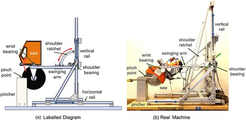
The motion capture harness is mounted on a mechanized Cartesian positioning system which moves the center of mass of the saw relative to the fixed pincher. The positioning system consists of two sets of linear rails, horizontal and vertical, with motion driven by parallel leadscrews, one mounted on each rail. Encoder motors on each leadscrew position the saw with a dual proportional–integral–derivative control loop. The leadscrews are selected to be non-back-drivable, allowing them to hold position during kickback without requiring active locking. Moving the motion capture harness and saw relative to the pincher allows for the initial angle of the saw body, θ, to be changed while still engaging the pincher in a symmetric fashion and keeping the initial rO horizontal. This set-up aligns the initial kickback force with the vertical degree of freedom. The positioning system also allows for saws of different geometries to be tested while only requiring a change in the center of mass coordinates based on the length from C to O and the cutting blade diameter. A labeled diagram and image of the full test machine are shown in Figure .
Figure 7. Test machine used in this study: (a) labeled diagram and (b) image of the full test machine. Note: The full color version of this figure is available online.
An end positioner was mounted to the pincher to ensure that the center of the cutting element is aligned horizontally with the pinch point at the start of the engagement. This positioner also ensures that the initial angle of the saw body is verifiable and that the cutting element is consistently positioned relative to the work material. Given the small size of both the work material and the abrasive region of the cutting blade, small variations in the initial contact angle could significantly affect the engagement of the cutting element during the pinch. This positioner and the locating pin on the saw are shown in Figure a.
Figure 8. (a) End positioner and (b) two-part tie down used to improve the repeatability of testing. Note: The full color version of this figure is available online.
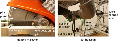
A two-part tie down is used to secure the saw in place while it is running prior to initiating kickback. The first part is a rigid latch, which resists the initial kickback of the saw due to start up. It is released manually prior to initiating kickback. The second part is a breakaway connection, which holds the saw in place until the initial kickback force releases it. The two-part tie down is shown in its fully engaged state in Figure b.
2.2.3 Pinching mechanism
Theoretical predictions indicated that a pinching mechanism would need to be capable of applying up to 3 kN of normal force and be able to fully engage in less than 20 ms. Additionally, in order to evaluate the effects of different pinch forces on kickback, the pinch force would have to be able to be repeatedly varied. To meet these functional requirements, the pinching mechanism was designed as a pneumatic spring actuating a pair of levers to pinch the cutting blade. A long pneumatic cylinder is mounted onto one lever and pushes on the other lever, while a hair trigger holds the two levers in place prior to kickback. The levers are mounted with widely spaced bushings to provide the force couple needed to resist moments, allowing for proper resistance of both vertical and horizontal kickback reaction forces. Single-use pinch pads, made from hexagonal stock to resist twisting in their seats, are used to emulate the kerf work material and are mounted to the tops of the levers to directly pinch the saw blade. A diagram illustrating the inner workings of the pinching mechanism is shown in Figure . The pinching mechanism is housed in a 6061 aluminum 150 mm × 150 mm × 12.5 mm square tube which provides structural rigidity for the system. A slit in the front and back of the top of the housing allows for the saw blade to swing through the housing.
Figure 9. Labeled diagram showing internal components of the pinching mechanism. Note: The full color version of version of this figure is available online.
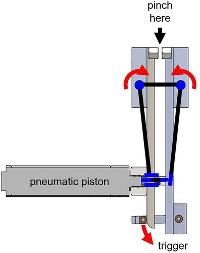
A pneumatic system is used for adjustable high-force generation. Varying the pressure in the piston linearly varies the pinch force. Additionally, pre-pressurizing the piston and holding the mechanism open with a hair trigger allows for fast actuation without being limited by air flow rates as the piston undergoes adiabatic expansion. A piston cylinder of diameter 50 mm and length 125 mm. was chosen. The diameter of the piston was chosen to achieve appropriate pinch forces, and the length was chosen to be much longer than the required stroke. The piston rod was cut short so that the piston always operates at more than 90% extended, thereby limiting the maximum pressure loss due to adiabatic expansion. Moreover, for all cutting elements of the same thickness, the pressure loss is the same.
Levers were sized to provide an additional three times force multiplication of the piston. These levers are configured in a class 1 lever configuration, allowing for the pinch point to be at the top of the pinching mechanism, while the rest of the hardware resides safely below the path of the saw blade. The lower part of the levers forms a five-bar linkage, with the end of the pneumatic piston able to slide on the surface of one lever, allowing for centered force application. Unlike in a common five-bar linkage, like a set of bolt cutters, two links are replaced by the pneumatic piston and its extending rod. This design allows the saw blade to be symmetrically pinched in a repeatable fashion.
At the output of the pinching mechanism, single-use pinch pads are mounted to directly engage the saw blade. These pinch pads are turned on a screw machine from 20 mm. hex stock with a 1/4–20 tapped hole through their central axis. They are mounted to the levers using 1/4–20 bolts. Additionally, shelves were milled out of the levers to provide vertical force transmission and to hold the pinch pads irrotationally.
2.3 Testing protocol
To prepare a saw for testing, the saw is mounted in a harness that allows it to rotate freely about its center of mass. For each test, the machine repositions the saw's center of mass such that the cutting element is centered in the pinch point and the initial contact angle of the saw is as desired. The saw is then locked in position with the two-part tie down. Next, the saw is started and allowed to reach full speed. The pinch is then engaged, generating the kickback. The rotational and translational positions of the saw are recorded by the motion capture harness during kickback. A hard stop prevents the saw from rotating beyond a directly vertical orientation, and upon reaching this position the saw throttle is released. The saw is then prepared for the next trial. The testing conditions and protocols are adapted to the specific saws as follows.
2.3.1 Electrical circular cutoff saw
The kickback machine was initially tested in a shielded indoor laboratory environment with an ECCS. With the ECCS, initial testing was conducted at a single pressure and a single contact angle to verify the consistency and accuracy of the data collected. Afterward, extensive testing of the ECCS was used to test the sensitivity of the physics model. Data were primarily grouped into sweeps across a range of initial contact angles. The initial contact angle was swept through for tests using different diameter blades and with multiple different pinch forces. The resultant data were compared to the predictions from the model.Footnote1
2.3.2 Gas-powered saws
The gas-powered saws were tested in an outdoor environment. The circular cutoff saw was used without water cooling, while the chainsaw was used with water cooling. Each saw was initially filled with the appropriate 50:1 gas–oil fuel mixture and refilled after each set of three trials. Also, the chain was re-tensioned each time the chainsaw was refueled. The results of the gas-powered saw testing are used to show the kickback energy of industrial saws, as well as to compare the resultant kickback energies of the two saws.
3 Results and discussion
3.1 Kickback machine validation
The ECCS was used for the initial validation of the test machine since it allowed for a simpler and more consistent test set-up and procedure. This saw did not require water cooling or special ventilation, allowing it to be tested indoors. Also, the saw body was rigidly attached to the harness, simplifying the system. Further, the electric motor produced less vibration and pulsation, could be powered on and off by a switch and did not cause any change in mass during testing (unlike the consumption of gas during the gas-powered saw operation).
3.1.1 Overall machine repeatability
The kickback machine was tested for repeatability to determine the overall error attributable to the test machine itself. Testing consisted of verifying the linear encoder measurements and producing nine kickbacks with the ECCS using a blade 30 cm in diameter. The blade was pinched with a pinch force of 1260 N and an initial contact angle of 20°. The linear, rotational and total mechanical energies were found to have relative standard deviations of 6.9, 11.4 and 7.5%, respectively. These results, which can be seen in Appendix 1, increase confidence that variation seen in the data is not primarily due to factors from the test machine. Further, the measured resultant kickback energy values were of the same order of magnitude of the kickback energy found in woodcutting saw tests done by Dabrowski [Citation10], demonstrating that the kickback event generated is representative of dangerous kickback that can occur during normal saw operation.
3.1.2 Work material
For testing in this investigation, 6061 aluminum and mild steel pinch pads were used. However, in the future, additional materials could be used. An example of the 6061 aluminum pinch pads used is shown in Figure .
Figure 10. Pinch pads used during testing. Note: 1, the initial cut by the abrasive edge; 2, a second area of engagement during the kickback event; 3, the area contacting Region II of the saw. The full color version of this figure is available online.
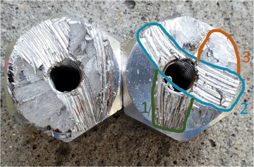
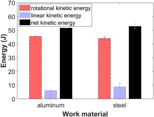
A majority of testing was performed with 6061 aluminum pinch pads due to their ease of manufacture and theorized high µ value when engaged with diamond abrasive cutting surfaces. The cutting application being examined, however, was the cutting of ductile iron pipe. Thus, mild steel pinch pads were fabricated and used to compare to the tests with aluminum pinch pads. This testing did not show a significant difference in the data produced using each material, as seen in Figure .
Figure 11. Comparison of measured kickback energy using steel and aluminum work material. Note: The error bars indicate the range of measured values. The full color version of this figure is available online.
While aluminum pinch pads were the material primarily used for testing, some gas-powered saw trials conducted using mild steel pinch pads resulted in the observation of notable trajectories. These tests showed an initial kickback energy at or slightly below the observed levels from the aluminum pad tests. However, the blade had more difficulty disengaging from the pinch point. This effect is amplified by the compliance of the vibration isolator springs in the gas-powered saw harnesses, allowing the saw to move such that the abrasive remains engaged in the pinch point while the motion capture harness moves separately. This total motion is not fully observed by the motion capture harness, as the linear component of the force vector starts to align with the horizontal, so its contribution is not fully measured. Because the initial kickback energy before this extra motion matches the energy levels observed during testing with aluminum as a work material, the testing with aluminum pinch pads remains valid for evaluating the kickback energy of these saws during ductile iron pipe cutting.
3.2 Model validation
The ECCS was also used to validate the model conclusions for the reasons outlined in Section 3.1. The independent parameters tested for model validation included the initial contact angle, cutting blade diameter and pinch force.
3.2.1 Initial contact angle sensitivity
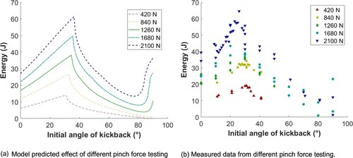
The first model parameter examined was the initial angle of the kickback, θ, as shown in Figure . In the field, the initial contact angle varies widely with how the user is holding the saw and the cut they are making, indicating the importance of characterizing its effect on kickback. For almost all tested combinations of saws, blade diameters and pinch forces, the kickback energy tends to increase as the initial angle increases, reach an abrupt peak at a specific angle and then rapidly decrease again. This phenomenon agrees with predictions by the model and can be seen in Figure .
Figure 12. Sample data set compared with the model prediction for the ECCS with a blade 30 cm in diameter and a pinch force of 1680 N. Note: The full color version of this figure is available online. ECCS = electric circular cutoff saw; LKE = linear kinetic energy; RKE = rotational kinetic energy.
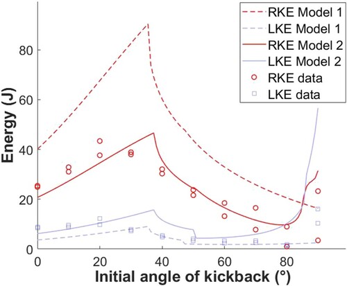
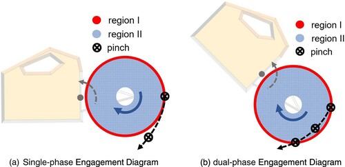
Examinations of the simulation and of used pinch pads indicate that a transition in the nature of the engagement between the cutting blade and the work material occurs around the angle corresponding to the peak kickback energy. The contact transitions from a single-phase engagement to a dual-phase engagement. Single-phase engagement refers to when the work material maintains continuous engagement with the abrasive region of the cutting blade throughout the engagement part of the kickback event, as illustrated in Figure a. Dual-phase engagement refers to when the work material engages the abrasive region of the cutting blade during two discrete times in a single kickback, as illustrated in Figure b. The first engagement with the abrasive region of the saw occurs at initiation and ends when the saw moves so that the work material engages the low-friction interior of the cutting blade/saw bar (Regions II and III). The second engagement occurs when the saw moves such that the work material re-engages the abrasive region of the saw, and it ends when the saw fully separates from the work material.
Figure 13. Path that the pinch point traces on the blade relative to the motion of the saw during (a) single-phase and (b) dual-phase engagement. Note: The full color version of this figure is available online.
This change in abrasive engagement provides a physical explanation for the change in the resultant kinetic energy of the saw. The linear friction approximation implies that the engagement region with the highest coefficient of friction, the abrasive, could dominate the kickback event. As the initial angle increases from zero, the work material remains engaged with the abrasive region over a longer distance. However, when the transition from single to dual engagement occurs, the length of the work material engagement with the abrasive region becomes shorter, and it further decreases as the initial angle continues to increase.
The observation of this trend in kickback energy in both the experimental data and the model predictions supports the validity of the model. Moreover, the observation of the suspected cause, a shift from single-phase to dual-phase engagement, in both experimental data and the model predictions further indicates that the model is capturing a characteristic behavior of pinch-based kickback.
3.2.2 Blade diameter sensitivity
The cutting blade diameter was selected as a test variable as it represents one of the most easily and often changed parameters of a saw. Additionally, as the cutting blade diameter increases, both the area that presents a kickback risk and the length of a potential engagement increase, leading to an expected increase in the kickback risk [Citation11]. The cutting blade diameter is also one of the main differences between how the model treats a chainsaw and a circular cutoff saw. To test the model's prediction for the effect of changing the saw blade diameter on the resultant kickback energy, the ECCS was tested with four different diameter blades. According to the model, the kickback energy should increase as the diameter of the blade increases. Also, for larger diameters, the peak energy should occur at a smaller initial contact angle. These predicted trends are related to the change in the length of the abrasive region engaged by the work material as the diameter of the blade changes. These predictions are shown in Figure a. The broken lines represent the predictions of Model 1, while the solid lines represent the predictions of Model 2.
Figure 14. Comparison of the predicted (a) and measured (b) change in kickback energy for an increase in the diameter of the blade. Note: The full color version of this figure is available online. Broken lines, prediction by Model 1; solid lines, prediction by Model 2. Data for 20 and 30 cm blades are close to the Model 2 predictions, while data for 25 and 36 cm blades are closer to the Model 1 predictions.
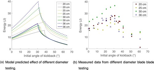
The collected data do not show either of these expected changes, contradicting the expected result [Citation11] of an increase in kickback energy with blade diameter; instead, all four sets of data show that the peak energy occurs around the same contact angle, near 30°, and the smallest and largest diameter blades produce similar, medium levels of kickback energy. Additionally, while the kickback energy observed during testing with the blades 8 and 12-in. in diameter agree more with the predictions of Model 1, the results from testing the blades 25 and 36 cm in diameter are closer to the predictions of Model 2. This observation suggests that the accurate model of the saw would be somewhere between the simplifications made in each model.
One potential explanation for this observed discrepancy is that the blades differed in abrasive patterning, as shown in Figure .
Figure 15. Different abrasive patterns on the different diameter blades. Note: The full color version of this figure is available online.
Notably, the blades 20 and 36 cm in diameter have a similar abrasive pattern and produce similar levels of kickback, indicating that the abrasive pattern could be more significant than the blade diameter in determining kickback energy. However, further testing using blades with different diameters and the same abrasive pattern, as well as blades of the same diameter with different abrasive patterns, would be necessary to verify this claim. This further testing would also be necessary to validate the observation that the two models seem to bound the resultant energy, as the abrasive pattern could have an overriding, unobserved effect.
3.2.3 Pinch force sensitivity
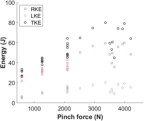
To further test the model's predictions, the pinch force used to generate the kickback was varied while keeping the blade diameter constant. The pinch force represents an environmental condition, so changes in kickback energy during this testing represent how the model predicts changes in response to the conditions creating the kickback. Since the actual pinch force in practice can vary, this quantity would not be known in advance for kickback energy prediction in the field. However, this analysis can be used to demonstrate the potential danger of the kickback under progressively more dangerous conditions.
Because the modeled kickback force is much larger than gravity, the model predicts that the kickback energy should increase linearly with pinch force. Changing the magnitude of the pinch force changes the rate at which the saw translates and rotates, but the spatial trajectory of the saw remains the same. The corresponding data, shown along with this prediction in Figure , shows the expected increase in kickback energy as normal force increases. However, the observed increase is not definitively linear. The increase is rapid from a low to medium force, then slow for the next two incremental increases and then rapid again to the highest applied force.
Figure 16. Comparison of the predicted (a) and measured (b) change in kickback energy for an increase in the normal force on the blade. Note: (a) Only Model 2 predictions presented to illustrate the trend as pinch force increases. Model 1 predictions follow a similar trend but at lower magnitudes. Note: The full color version of this figure is available online.
Further testing of increasing the normal force was performed with two other blade diameters of 20 and 36 cm Again, the model predicts that the kickback energy should increase linearly as normal force increases. The data for these experiments are shown in Figure .
Figure 17. Increasing pinch force with a constant diameter blade and initial contact angle. Note: (a) Shows that increasing the pinch force, the initial resultant kickback energy is linear, as predicted by the model. However, once the pinch force is high enough to cause the blade's motion to come to a momentary stop, the kickback energy begins to decrease, until the saw is completely caught in the pinch and there is no kickback. (b) In testing with a larger diameter blade shows a similar initial linear increase in resultant kickback energy, it does not show a later decrease in resultant kickback energy. Instead, there is a transition to a less steep linear slope. Note: The full color version of this figure is available online.
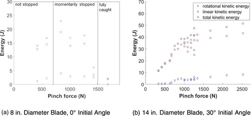
For both blades, the increase is initially linear. However, testing with both diameter blades indicates the existence of a transition point, after which the behavior changes. For the 20 cm blade, this behavior is associated with stopping of the blade during kickback, although the saw body would keep moving, as revealed by high-speed video. This continued motion would enable the saw to pull itself loose and start spinning the blade again, so the kickback event would continue. However, this instantaneous stop would reduce the resultant energy with which the saw would leave the engagement point. These data represent a limitation of the model, as the model does not allow for changes in the speed of the blade. The maximum energy appears to correspond to the point at which the blade is first stopped. This point indicates when no additional energy can be extracted from the blade. For the 36 cm blade, the kickback energy continues to increase linearly, albeit at a much lower rate. High-speed video was not taken during this testing, so it cannot be verified whether there is also an instantaneous stopping of the blade at/after this transition point.
3.3 Gas-powered saw testing
After testing the strengths and limitations of the model's predictions, the test machine was used to measure the kickback energy for two industrial gas-powered saws, the circular cutoff saw and the abrasive chainsaw. Both of these saws exhibit the same kind of peaked curve of kickback energy with respect to the contact angle as found with the ECCS, agreeing with the model. These data and the corresponding model predictions are shown in Figure . It is observed that when pinched with higher forces, the chainsaw has significantly more variability in the measured kickback energy than the cutoff saw. This variability is likely due to the non-uniformity of the diamond abrasive chain, which has abrasive on opposite sides of every other chain link. Since the collected data are reasonably close to the predictions from the model, they are valid for comparing the kickback safety risk of these two types of saws. Plots comparing the measured kickback energy of these two saws at three different pinch force levels are shown in Figure .
Figure 18. Subfigures a-f compare the measured kickback energy data to the model predicted kickback energy for the chainsaw (a, c, e) and the circular saw (b, d, f) at three different pinch force levels: 588 N (a, b), 1260 N (c, d), and 2100 N (e, f). Note: The full color version of this figure is available online. LKE = linear kinetic energy; RKE = rotational kinetic energy; TKE = total kinetic energy.
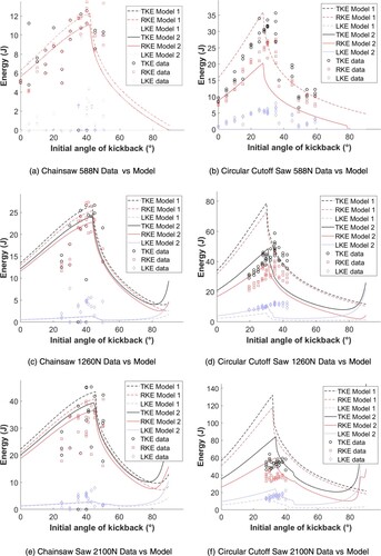
Figure 19. Comparison of the kickback energy data for the circular cutoff saw (Stihl TS420; Stihl USA, USA) and the chainsaw (ICS 695XL; Blount International, USA) for angle sweeps at three different normal force levels: (a) 588 N, (b) 1260 N and (c) 2100 N. Note: The full color version of this figure is available online. LKE = linear kinetic energy; RKE = rotational kinetic energy; TKE = total kinetic energy.
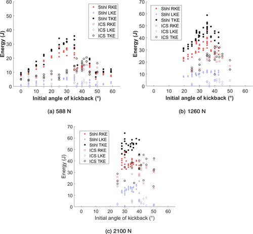
These plots show that the two saws generate peak kickback energy at two different initial contact angles, as anticipated by the model. At the chainsaw's peak energy, around an initial contact angle of 42°, the rotational kinetic energy is comparable to that of the circular cutoff saw, given the same initial contact angle. However, because the circular cutoff saw has a greater linear kinetic energy at nearly all initial contact angles, particularly as the normal force increases, the total kickback energy (for equal weighting of linear and rotational kinetic energy) is greater for the circular cutoff saw. For initial contact angles larger than 42°, the rotational kinetic energy of both saws is expected to remain similar, as the energy level of both saws would decrease. At lower initial contact angles, all energy measurements are higher for the circular saw, including at the circular cutoff saw's peak energy around an initial contact angle of 30°.
3.3.1 High-pressure testing
While testing with a pinch force of 2100 N started to occasionally catch the nose of the chainsaw such that it remained stuck in the pincher rather than kicking back, these tests did not result in the circular cutoff saw blade being caught. Since testing with the ECCS verified that further increasing the pinch force would increase the resultant kickback energy, the circular cutoff saw was also tested at higher pinch forces to approach an experimental maximum kickback energy. The results of this testing, shown in Figure , indicate that the resultant energy increases to a plateau, then begins to decrease as the pinch force continues to increase. While high-speed video does not capture any momentary catching of the saw blade during these tests, these data indicate that there is a finite limit to how much energy can be transferred to saw motion during kickback.
Figure 20. High-pressure testing for the circular cutoff saw with an initial contact angle of 31°. Note: The full color version of this figure is available online. LKE = linear kinetic energy; RKE = rotational kinetic energy; TKE = total kinetic energy.
3.3.2 Vibration isolator effects
Both of the gas-powered saws have vibration isolator springs between the saw body and the saw handle. Analysis of high-speed video indicated that the compliance of these springs allowed for a difference in the rigid body motion of the saw itself and the motion of the handle, which is measured by the harness. Since the springs are conservative, any energy stored in the springs would create oscillations in the motion of the handle and the rigid body. The frequency of these oscillations observed in the data could be measured and compared to the natural frequency of the saw–spring–handle system. The measured and predicted frequencies matched to within 10% error.
The measured amplitude of these oscillations indicates the displacement of the springs, from which the stored energy can be calculated. Based on the measured stiffness of the springs, the calculated stored energy was about 0.05 J for each saw. This level of energy storage confirms that the kickback energy is primarily transmitted into rigid body motion, rather than into the vibration isolators. Hence, the effects of the vibration isolators can be neglected.
3.3.3 Stopping the cutting element
As mentioned in Section 2.1.2, the model assumes a constant speed for the cutting blade. While this assumption would allow kickback energy to increase with pinch force without an upper limit, this case does not match observations. Experimental results demonstrate that this assumption starts to break down as the pinch force increases and the cutting blade diameter decreases. The 20 cm blade was observed to have stopped instantaneously during some kickback trials, but a lack of high-speed video analysis for other diameter blades or the gas-powered saws prevents confirmation of whether the same phenomenon occurs for those blades or the chainsaw chain given the tested conditions. However, the entire saw tip was stopped and caught during some of the chainsaw testing, indicating that the chainsaw was nearing a potential maximum possible energy, as a blade caught in the work material would not kick back. In this case, the pinching work material absorbs all of the kickback energy, stopping both the motion of the cutting element and the saw body. This phenomenon differs from the use of a chain or blade brake to prevent kickback, as the kickback energy is typically completely transferred to the saw/operator before the brake is actuated. Further testing at higher pinch forces, along with high-speed video analysis, would allow for identifying the upper boundary of kickback energy of a saw for unknown pinch conditions.
4 Conclusions and future work
This work demonstrates that pinch-based abrasive saw kickback can have energy levels comparable to woodcutting saw kickback, even though the kickback mechanism differs. The friction-based model used for analyzing kickback of abrasive saws captures the abrasive saw kickback phenomenon and can be used to provide an initial expectation for the kickback energy potential of a given saw. Additionally, the designed and developed test machine can repeatedly and accurately measure the kickback energy produced by a given saw. Furthermore, the results indicate that the parameters of a chainsaw generate less energy than those of a circular cutoff saw given the same kickback conditions. The increased risk due to the high measured and predicted kickback energy of the circular cutoff saw is amplified by the fact that cutting a pipe in an excavated trench with a circular cutoff saw requires the kickback zone to be engaged to completely cut through a pipe. The model and test machine developed in this work indicate that pinch-based kickback can present a safety risk for operators of abrasive saws, and this work provides a reliable method for measuring this risk. It is envisioned that the model together with the test apparatus can help manufacturers develop safer saws in a deterministic manner.
Future work should include more data collection for saws with different abrasive patterns and the same diameter of blade, as well as the same abrasive patterns on different diameter blades to investigate the effect of abrasive patterning on resultant kickback energy. Additionally, more data can complete the angle sweeps performed with the gas-powered saws to develop a more complete picture of the kickback behavior, particularly at higher pinch forces. Also, the effect of different work materials could be investigated further using materials with extreme properties (such as Teflon, which has a high shear strength but a low coefficient of friction).
Disclosure statement
No potential conflict of interest was reported by the authors.
Additional information
Funding
Notes
1 Testing was also performed with a cutterless electric woodcutting chainsaw; however, the lack of an abrasive cutting region made the results chaotic and unreliable.
References
- Koehler SA, Luckasevic TM, Rozin L. et al. Death by chainsaw: fatal kickback injuries to the neck. J Forensic Sci. 2004;49(2):1–6. doi: https://doi.org/10.1520/JFS2003276
- Haynes CD, Webb WA, Fenno CR. Chain saw injuries: review of 330 cases. J Trauma. 1980;20(9):772–776. doi: https://doi.org/10.1097/00005373-198009000-00011
- Arnold D, Parmigiani J. A method for detecting the occurrence of chainsaw kickback. Dyn. Syst. and Control; Mechatron. and Intell. Machines, Parts A and B, ASMEDC. 2011;7:441–447.
- Robinson D. Evaluation of chain saw simulated kickback modes. Cent. Manuf . Eng. (MD): National Bureau of Standards (US); 1984. (Washington, DC: NBSIR publication; no. 84-2823).
- Commission approves mandatory approach toward reducing chain saw injuries from ‘Kickback’. Consumer Product Safety Commission (US); 1980. (Bethesda, MD: CPSC release; no . 80-023).
- American National Standards Institute (ANSI)/Outdoor Power Equipment Institute (OPEI). Internal combustion engine-powered hand-held chain saws – safety and environmental requirements. New York: ANSI/OPEI; 2014. Standard No. B175.1-2012.
- Wu J. Theoretical investigation of kickback in diamond chainsaw and circular cut-off saw [master’s thesis]. Cambridge (MA): MIT; 2018.
- Yue BJ. Evaluation of kickback energies in abrasive chain saws and cut-off saws: a theoretical and experimental study [master’s thesis]. Cambridge (MA): MIT; 2019.
- Arnold D, Parmigiani JP. A study of chainsaw kickback. For Prod J. 2015;65(5–6):232–238.
- Dabrowski A. Kickback risk of portable chainsaws while cutting wood of different properties: laboratory tests and deductions. Int J Occup Saf Ergon. 2015;21(4):512–523. doi: https://doi.org/10.1080/10803548.2015.1095547
- Chainsaw kickback explained: learn how to avoid the danger [Internet]. Oregon Products; c2019. Available from: https://www.oregonproducts.com/en/chain-saw-kickback.
Appendix A. Machine repeatability
Appendix A1. Data from repeatability testing
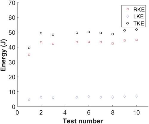
The test data used to determine the overall repeatability of the test machine are shown in Figure . While these data indicate that the overall machine produces consistent data, the linear kinetic energy measurements were shown to be much lower than the rotational kinetic energy measurements. Because of the relatively low magnitude of these linear kinetic energy measurements, it was deemed important to verify the accuracy of these measurements with a secondary measurement system. This verification is discussed in Section A2.
Figure A1. Plot of the rotational, linear and total kinetic energy for multiple tests of the same test set-up. Test 4 encountered a recording error and has been omitted. Note: The full color version of this figure is available online. LKE = linear kinetic energy; RKE = rotational kinetic energy; TKE = total kinetic energy.
Appendix A2. Linear kinetic energy measurement
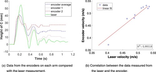
Given the arms’ relatively small angular displacement during saw translation, the position data measured generally have low resolution. The system's accuracy was measured by mounting a laser on top of one arm on the end opposite the pivot point of the arm. The laser was oriented to shine along the arm's length and project onto a surface 0.5 m away. A camera was used to track the motion of the projected dot throughout nine kickback trials, and the angle of the arms at each point was calculated based on the measured data. The measurement of the arm's position with the laser is shown with the encoder measurements in Figure a. The peak linear velocity was calculated using the encoder measurement and compared to the velocity calculated using the laser measurement. This comparison is shown in Figure A2b. On average, the encoder-measured velocity was within 99.3% of the laser-measured velocity, supporting the conclusion that its resolution and accuracy were high enough to measure the linear velocity of the saw.
Figure A2. Comparison of laser-measured and encoder-measured linear position data: (a) representative of one trial and (b) summarized correlation over nine trials. Note: The full color version of this figure is available online. C = center of mass of the saw. The laser was mounted to the arm whose position is measured by Encoder 1.