
Abstract
The use of personal protective equipment, including a safety harness, is one of the basic methods of protection against falls from a height. The presented studies, using an anthropomorphic dummy, identified the effect on the human body of the dangerous phenomena accompanying safety harness performance during fall arrest. The displacement of the dummy in the safety harness, the mutual displacement of the adjustment buckles and the webbing of the harness, the tightening of the straps on the dummy and the impacts exerted on the head of the dummy by the harness elements were considered. The correlation between the design of the safety harness and the parameters and phenomena in question has been demonstrated. It has been shown that for the purposes of assessment of novel harness designs it is necessary to carry out studies utilizing an anthropomorphic dummy in addition to resistance tests.
1 Introduction
Fall from height constitutes one of the most serious occupational hazards in the construction, energy and mining industries, as well as in many other sectors. The scale of the problem is reflected in workplace accident data from the Central Statistical Office [Citation1]. In 2017 in Poland, a total of 5379 falls from height were reported, 70 of which led to serious injury and 38 to death. In the construction industry alone there were 600 fall-related accidents, including 16 fatalities and 24 cases of serious injury.
One of the most widespread methods of protecting individuals working at elevated positions is the use of personal fall protection equipment. In industrial settings, such equipment may be divided into three major functional categories:
fall arrest systems;
restraint systems preventing fall initiation;
work positioning systems.
Fall arrest systems are used where the risk of a fall from height cannot be entirely eliminated, in particular in the construction industry, whilst working on steel structures, etc. Thus, as a last resort, such systems are tasked with the most precarious and critical function of saving the user in freefall. A typical fall arrest system consists of three basic elements:
an anchor device attached to a structural element of the work site [Citation2];
a shock-absorbing connecting assembly designed to mitigate the kinetic energy of the falling person [Citation3–7];
a safety harness [Citation8].
Safety harnesses remain in direct contact with the human body and are responsible for:
arresting the user’s fall;
distributing the dynamic forces acting on the user to the most resilient body parts;
positioning the human body during fall arrest;
enabling a safe and reasonably comfortable position while awaiting help after fall arrest.
Additionally, advanced safety harnesses may facilitate rescue functions (lowering from a height, raising from confined spaces), enable work in a suspended or supported position, etc.
These functions show the critical role of safety harnesses in fall arrest equipment and their crucial significance for the user’s health and life. Therefore, the assessment of the protective parameters of the harness before delivery to users is very important. Previous experiences in the field of testing and the use of full body harnesses show that their construction significantly affects the performance during fall arrest from a height, which affects the safety of users. In addition, the thesis can also be formulated that currently used test methods in which a rigid torso is used are not sufficient for a comprehensive assessment of the safety parameters of the full body harness. At present, there are no scientific publications pointing to this problem, especially in relation to new constructions of safety harnesses available on the EU market.
The present article describes recent studies of full body harness performance under dynamic conditions, using modern scientific equipment including an anthropomorphic dummy, in order to prove formulated theses and provide data relevant for ensuring human safety.
2 The state of the art
Currently, safety harnesses are tested for conformity with the EU Regulation on personal protective equipment (PPE) [Citation9] by notified laboratories pursuant to the methods stipulated in Standard No. EN 361:2002 [Citation8] and Standard No. EN 364:1992 [Citation10], which are harmonized with that regulation. Safety harnesses are examined under dynamic fall arrest conditions using a dummy specified in Standard No. EN 364:1992 [Citation10], which has the shape of a human torso without a head or arms and weighs 100 kg, with its center of gravity corresponding to that of a human. However, it should be noted that the mechanical parameters of the dummy, and especially its rigid structure and hard surface, make it substantially different from the human body. Therefore, the dummy is mostly applied in strength tests checking whether or not it is likely to be released by the harness system upon fall arrest. The only measured parameter pertaining to harness behavior is the angle formed between the dorsal plane of the dummy and the vertical plane after fall arrest. Such tests provide practically no information about dummy displacement in the harness during fall arrest, changes in buckle adjustment, strap impact on the dummy’s head and neck, and other phenomena occurring at the harness–human interface.
Given the aforementioned, research into safety harnesses should involve models that better reflect the mechanical properties of the human body, such as the anthropomorphic dummies widely used in automotive, aviation and aerospace applications. A good example of the development of anthropomorphic dummies is the Hybrid series [Citation11,Citation12], and especially the Hybrid III model employed in human safety studies in various fields of science and technology. Many interesting examples of the use of anthropomorphic dummies in vehicle testing have been provided to date [Citation13–17].
Anthropomorphic dummies have also become very valuable tools in examining the mechanical phenomena occurring in sports disciplines in which humans are exposed to dynamic loads [Citation18–20]. Furthermore, Deemer et al. [Citation21] and Raymond et al. [Citation22] presented a test methodology involving dummies for studying falls on flat surfaces.
A Hybrid II dummy was used in investigations of personal fall protection equipment at the Berufsgenossenschaftliches Institut für Arbeitssicherheit (BIA) in Germany [Citation23]. The study concerned arresting the fall of an upright dummy that did not come into contact with elements of the work site, with a focus on head acceleration, the fall arrest force and the pressure exerted by the textile straps on the dummy surface. The next-generation dummy, i.e., the Hybrid III Pedestrian, was employed in research conducted at the Central Institute for Labour Protection – National Research Institute in Poland that addressed swing falls resulting in collisions with structural elements [Citation24,Citation25]. These examples indicate the substantial application potential and advantages of anthropomorphic dummies in investigating fall arrest phenomena.
One of the basic parameters characterizing fall arrest is the maximum fall distance, defined as the distance between the surface on which the person was supported prior to fall and his or her lowest position in fall arrest. The fall distance directly affects the risk of collision with the structural elements of the work site. It depends on the properties of the applied protective equipment and the distance between the workplace level and the anchor point. The ability to accurately evaluate the fall distance is indispensable for the safe organization of work at height. In the case of personal fall protection systems, the fall distance can be estimated from a combination of the following components:
the length of the energy-absorbing connecting assembly and the individual’s position with respect to the anchor point at fall initiation;
deflection of the anchoring system, e.g., a horizontal anchor line;
elongation of the energy-absorbing connecting assembly, such as a shock absorber and a lanyard;
elongation of the safety harness and its displacement on the user’s body.
Knowledge of these components enables numerical modeling of the fall arrest process and evaluation of the fall path depending on the work site conditions and the equipment used.
Deflections of anchoring systems, and especially vertical and horizontal anchor lines, have been studied in a number of theoretical and empirical papers, including those by Baszczyński and Zrobek [Citation26,Citation27], Miura and Sulowski [Citation28] and Baszczyński [Citation29]. Other publications have explored fall-arrest-induced elongation of energy-absorbing connecting assemblies [Citation30–35]. Thus, appropriate methods for the study of those phenomena are deemed to have been developed. In contrast, there is a scarcity of reliable data on the elongation of commercially available safety harnesses and the displacement of the user’s body upon fall arrest. Reports from existing fragmentary studies indicate that the user’s displacement in the harness (with respect to the sternal or dorsal attachment point) is attributable to:
elongation of the textile straps comprising the harness;
straps slipping in adjustment buckles and attachment fittings;
harness draping on the human body.
Taking into account the results of dynamic studies on the elongation of textile straps used in safety harnesses [Citation33,Citation34], only the first of these phenomena can be theoretically estimated. According to those publications, the relative dynamic elongation of straps 44 mm wide ranges from 3 to 11%, depending on the textile material. If the construction of a safety harness is simplified to four parallel straps 1 m long, their elongation under an overall load of 6 kN would be approximately 8–28 mm, which is relatively little compared to the elongation of textile shock absorbers/lanyards, which may exceed 1.5 m.
In turn, the evaluation of the other two phenomena requires experimental studies with an anthropomorphic dummy, which is the subject matter of this work.
3 Methodology and experimental setup
In the present work, the behavior of safety harnesses during fall arrest was studied using a Hybrid III 50th Percentile Pedestrian anthropomorphic dummy from Humanetics (USA) [Citation11,Citation12] fitted with different full body harness models and a test lanyard. The following mechanical parameters were measured during fall and after its termination:
dummy displacement in the harness, defined as Δ = xb – xa (see );
slippage of straps in adjustment buckles;
tightening of the shoulder straps around the dummy’s neck and/or head;
impact of the sternal attachment (D-ring) to the dummy’s head.
Figure 1. Experimental setup for testing safety harnesses during fall arrest. Note: 1 = rigid beam; 2 = crane; 3 = electromagnetic latch; 4 = anthropomorphic dummy fitted with a safety harness; 5 = high-speed digital video camera; 6 = computer connected to the camera; 7 = lanyard; 8 = computer with a data-acquisition system; 9 = force transducer with an analog filter and amplifier; A = state prior to fall initiation; B = state following fall arrest.
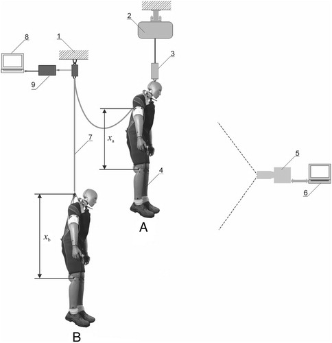
The aforementioned investigations were carried out using the setup schematically shown in .
The 78.15-kg dummy was developed based on the 50th percentile of selected anthropometric characteristics of the US population. Due to the design of its pelvic region, the dummy can adopt both erect and sitting positions, making it ideal for use with safety harnesses. During the study, it was fitted with a tested harness model, with either the sternal or dorsal attachment connected to the lanyard (7; see ). The 1-m-long lanyard was made from a dynamic climbing rope conforming to Standard No. EN 892:2012+A1:2016 [Citation36], with sewn loop ends. The other end of the lanyard (7) was connected to a Hottinger 9B 10-kN force transducer (9) measuring the fall arrest force acting at the anchor point attached to a rigid structure (1). The structure complied with Standard No. EN 364:1992 [Citation10] in terms of static load deformation and natural frequency of vibration. The experimental stand was equipped with a crane (2) to move the dummy both vertically and horizontally. An electromagnetic latch (3), which was secured on the hook of the crane (2), held the dummy. The dummy was lifted by a link located posteriorly at the base of its neck. The dummy could be suspended in the air or its feet could be positioned on a beam simulating the edge of the work site. The latch was released by an electrical signal to initiate the freefall of the dummy. The force transducer was connected to a MGA II amplifier (Hottinger, Germany), a MS210R/ET6 analog filter (IMD, Germany) (9) and a computer with a KUSB 3116 (Keithley Metrabyte, USA) data acquisition system (8). The fall of the dummy and the behavior of the harness during fall arrest was recorded using a Cube 7 MotionBLITZ EoSens® fast-speed camera from Mikrotron GmbH (Germany) (5) coupled to a computer (6) and set to 2000 fps.
The recorded material was analyzed using TemaMotion Starter II version 3.5 29 (Image Systems AB, Sweden) implementing image identification technology to determine the motion, speed and acceleration of selected points in sequences of frames [Citation37].
Based on preliminary tests, the dummy freefall distance was adopted as 1.3 m, and so the maximum fall arrest forces ranged from 5.25 to 6.25 kN, depending on the full body harness used. Prior to fall initiation, the dummy was placed in a vertical head-up position with the arms extended along its body.
4 Study material
In general, industrial full body harnesses conforming to Standard No. EN 361:2002 [Citation8] are made of textile straps joined by seams and metal connectors in such a way as to securely hold the user and support his or her weight. Typically, the shoulder straps cross at shoulder-blade level. Depending on the harness design, they are in some way combined with the thigh straps forming loops around the user’s legs. In addition, the thigh straps may be transversely connected in the gluteal region by a so-called sit strap. The straps are usually made from polyamide or polyester fibers, or, for special purposes (e.g., heat exposure), from aramid or other advanced fibers. The minimum width of load-bearing straps is 40 mm, and that of accessory straps is 20 mm.
Depending on the model, safety harnesses are equipped with various metal buckles and fittings. The most important of these are the sternal and dorsal lanyard attachments as well as adjustment buckles placed on the thigh and shoulder straps, which help to fit the harness to the user’s body. Harnesses also contain some elements made from synthetic materials, such as loops, cross patches, etc. Additional components may include a D-ring near the user’s center of gravity for controlled ascent and descent, and D-rings for work positioning placed laterally at the waist belt. The harness models investigated in the study are shown in .
Figure 2. Full body harnesses used in the study. Note: a1, a2, b1, b2, c1, c2, d, e1, e2, f1, f2 = adjustment buckles/fittings on the harness; A, B, C, D, E, F, G, H = harness types.
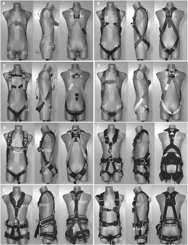
The full body harnesses were produced by the following manufacturers: harnesses A and B, Assecuro Sp. z o.o. (Poland); harness C, Lubawa S.A. (Poland); harness D, Protekt Grzegorz Łaszkiewicz (Poland); harness E, Kaya Safety (Turkey); harness F, Petzl (France); harness G, Rock Empire (Czech Republic); harness H, Beal (France)
5 Results
The selected safety harness models () were studied by means of the aforementioned methodology using the sternal and dorsal attachments according to the harness design. Five trials were made for either attachment point, and two or three harnesses of each model were used during experiments, depending on the test-induced defects. A new lanyard was used in every trial in order to ensure uniform study conditions. After each trial, the harness was removed from the dummy. If a given harness could be re-used, it was fitted on the dummy again pursuant to the manufacturer’s instructions. Trials involving the same full body harness were conducted at least 4 h apart. The mean values of results are presented in .
Table 1. Test results for the studied full body harness models.
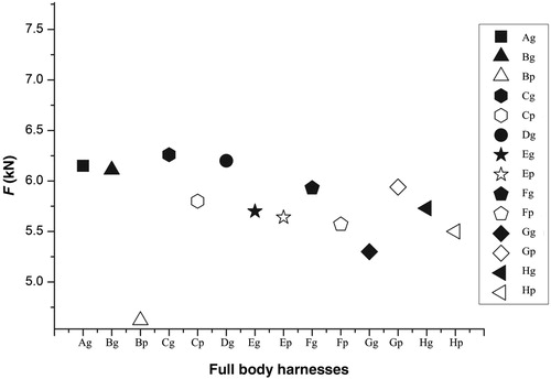
Maximum values of the force F acting at the lanyard anchor point during fall arrest are shown in Figure . Analysis of these results shows that in most cases F was in the range of 6.0 ± 0.5 kN, which indicates repeatable experimental conditions. Furthermore, a comparison of forces for sternal and dorsal attachments (in harness models B, C, E, F and H) revealed lower F values for the sternal attachments, which means that they had superior shock-absorbing properties.
Figure 3. Relationship between safety harness model and maximum fall arrest force F. Note: Ag, Bg, Cg, Dg, Eg, Fg, Gg, Hg = harness types equipped with a dorsal attachment point; Bp, Cp, Ep, Fp, Gp, Hp = harness types equipped with a sternal attachment point.
Analysis of fall arrest recordings from the fast-speed camera did not reveal any instance of the sternal attachment impacting the dummy’s face (head). However, harness models A, B and C were found to exert pressure on the dummy’s neck and head as a result of the dorsal D-ring sliding upward along the shoulder straps (see ).
Figure 4. Position of the shoulder straps and the dorsal attachment point in a safety harness after fall arrest.
These findings are consistent with the shoulder straps slipping in the buckles at points a1 and a2. The highest slippage values were found for harness models A, B, C, D and E, in which the shoulder straps crossed at the dorsal attachment point (in those cases, the dorsal attachment normally retains its designated position on the textile straps by the force of friction).
In the case of adjustment buckles at points b1 and b2 (on the anterior aspect of shoulder straps), the slip ranged from 2 to 14 mm. The smallest slip was found for the adjustment buckles on the thigh straps at points c1 and c2.
The mean values of the dummy’s displacement in the safety harness during fall arrest, with respect to the dorsal or sternal attachment points, are shown in Figures –.
Figure 5. Strap slippage in adjustment buckles (DD) and dummy displacement Δ in safety harness models A and D. Note: a1, a2, b1, b2, c1, c2, d, e1, e2, f1, f2 = adjustment buckles/fittings on the harness; Ag, Dg = harness types equipped with a dorsal attachment point.
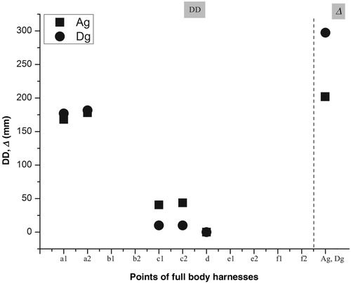
Figure 6. Strap slippage in adjustment buckles (DD) and dummy displacement Δ in safety harness models B, C, and E. Note: a1, a2, b1, b2, c1, c2, d, e1, e2, f1, f2 = adjustment buckles/fittings on the harness; Bg, Cg, Eg = harness types equipped with a dorsal attachment point; Bp, Cp, Ep = harness types equipped with a sternal attachment point.
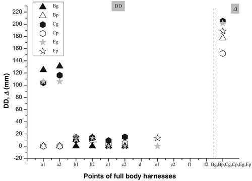
Figure 7. Strap slippage in adjustment buckles (DD) and dummy displacement Δ in safety harness models F, G, and H. Note: a1, a2, b1, b2, c1, c2, d, e1, e2, f1, f2 = adjustment buckles/fittings on the harness; Fg, Gg, Hg = harness types equipped with a dorsal attachment point; Fp, Gp, Hp = harness types equipped with a sternal attachment point.
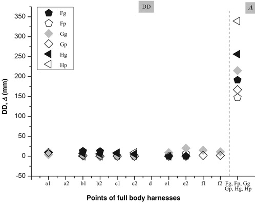
Dummy displacement Δ in the full body harness measured under dynamic conditions during fall arrest ranged from approximately 150 to 340 mm. The highest values were recorded for harness models B and H, and the lowest value for harness model F. In most cases of harnesses equipped with both sternal and dorsal attachment points (harness models B, C, E, F and G), greater dummy displacement Δ was found for the dorsal attachments.
6 Conclusions
The presented study with an anthropomorphic dummy revealed new phenomena in the behavior of safety harnesses during fall arrest. These phenomena concerned mainly shoulder straps as well as sternal and dorsal attachments of full body harnesses. In some models of harnesses, the dorsal attachment, e.g., a steel buckle, moved up along the shoulder straps. As a result, this caused the straps to tighten around the dummy’s neck and head, compressing them with their edges. Under actual conditions of use of safety harnesses, such behavior of their straps is dangerous to their user. The presented studies also showed that the displacement of the attachment buckles, especially sternal, can endanger the human face.
The displacement of the anthropomorphic dummy in the safety harness during fall arrest was also an important phenomenon identified in the present study. The value of this displacement, corresponding to the maximum permissible fall arrest force (6 kN), multiplied by an appropriate safety factor is necessary to estimate the fall arrest distance for personal equipment protecting against falls from a height.
Summing up the obtained results, it can be stated that the observed phenomena related to the behavior of the safety harness during fall arrests from height depended on their construction. In most cases, it was not possible to predict their behavior prior to testing. This confirms the thesis formulated in the Introduction that the behavior of the harnesses during fall arrest depends significantly on their construction, especially on the arrangement of straps and attachment buckles.
The identified phenomena have a direct impact on the safety of users of personal equipment protecting against falls from a height. Safety harness tests conducted according to the methods involving a rigid torso dummy stipulated in Standard No. EN 364:1992 [Citation10] and Standard No. EN 361:2002 [Citation8] are insufficient for a comprehensive evaluation of harness performance and their safety parameters. Thus, laboratories assessing and certifying new models of personal protective devices should consider the use of an anthropomorphic dummy in such investigations. The reason for this is the need to use a more faithful model of the human body than a rigid torso [Citation10], which confirms the thesis formulated in the Introduction to this article.
Since the aforementioned adverse effects were mainly associated with a considerable displacement of the shoulder straps and buckles, they may be considered to introduce appropriate requirements for the equipment evaluation. An example of such a requirement may be limiting the displacement of the dorsal attachment buckle to 50 mm, in the event of fall arrest of the anthropomorphic dummy. A similar restriction should be imposed on all other harness buckles and fittings to prevent their loosening, which could cause an adverse distribution of the forces acting on the human body during fall arrest (e.g., in the thigh loops). A safe limit on such displacements seems to be 20 mm.
Summing up the results presented in the article, it should be noted that they are the initial stage of research on the performance of safety harnesses during fall arrest. In previous studies, only the vertical position of the anthropomorphic dummy was used before the start of the fall.
Considering the significance of the results obtained, it is expected to continue testing for other dummy positions, e.g., head down, head inclined sideways and the position causing rotation. The study of such cases will allow the development of better criteria for assessing safety harnesses and their test methods.
Acknowledgements
This publication is based on the results of Phase IV of the multi-year program ‘Improvement of Occupational Safety and Working Conditions’, financed in the years 2017–2019 in the area of tasks related to services for the state by the Ministry of Family, Labor, and Social Policy. The program coordinator is the Central Institute for Labour Protection – National Research Institute.
Disclosure statement
No potential conflict of interest was reported by the author.
References
- Główny Urząd Statystyczny (GUS). Wypadki przy pracy w 2015 r [Occupational accidents in 2017]. Warszawa: GUS; 2018 [cited 2019 Oct 12]. Polish. Available from: http://stat.gov.pl/obszary-tematyczne/rynek-pracy/warunki-pracy-wypadki-przy-pracy/
- European Committee for Standardization (CEN). Personal fall protection equipment – anchor devices. Brussels: CEN; 2012. Standard No. EN 795:2012.
- European Committee for Standardization (CEN). Personal protective equipment against falls from a height: energy absorbers. Brussels: CEN; 2002. Standard No. EN 355:2002.
- European Committee for Standardization (CEN). Personal protective equipment against falls from a height: retractable type fall arresters. Brussels: CEN; 2002. Standard No. EN 360:2002.
- European Committee for Standardization (CEN). Personal protective equipment against falls from a height: guided type fall arresters including a flexible anchor line. Brussels: CEN; 2002. Standard No. EN 353-2:2002.
- European Committee for Standardization (CEN). Personal fall protection equipment. Lanyards. Brussels: CEN; 2010. Standard No. EN 354:2010.
- European Committee for Standardization (CEN). Personal fall protection equipment: guided type fall arresters including an anchor line: guided type fall arresters including a rigid anchor line. Brussels: CEN; 2014. Standard No. EN 353-1:2014.
- European Committee for Standardization (CEN). Personal protective equipment against falls from a height – full body harnesses. Brussels: CEN; 2002. Standard No. EN 361:2002.
- The European Parliament and the Council of the European Union. Regulation (EU) 2016/425 of the European Parliament and The Council of 9 March 2016 on personal protective equipment and repealing Council Directive 89/686/EEC. OJ. 2016;L81:51–98.
- European Committee for Standardization (CEN). Personal protective equipment against falls from a height – test methods. Brussels: CEN; 1992. Standard No. EN 364:1992.
- Humanetics. Crash test dummies [Internet]. Plymouth (MI): Humanetics; [cited 2017 Sep 16]. Available from: http://www.humaneticsatd.com/crash-test-dummies
- Humanetics. Hybrid III 50M pedestrian [Internet]. Plymouth (MI): Humanetics; [cited 2017 Sep 16]. Available from: http://www.humaneticsatd.com/crash-test-dummies/pedestrian/hybrid-iii-50m
- Jaśkiewicz M, Jurecki R, Więckowski D. Overview and analysis of dummies used for crash tests. Zeszyty Naukowe. Akademia Morska w Szczecinie. 2013;35(107):22–31.
- Viano DC, Parenteau CS, Burnett R. Influence of standing or seated pelvis on dummy responses in rear impacts. Accid Anal Prev. 2012;45:423–431. doi: 10.1016/j.aap.2011.08.009
- Peng Y, Chen Y, Yang J, et al. A study of pedestrian and bicyclist exposure to head injury in passenger car collisions based on accident data and simulations. Saf Sci. 2012;50:1749–1759. doi: 10.1016/j.ssci.2012.03.005
- Hu J, Klinich KD, Reed MP, et al. Development and validation of a modified Hybrid-III six-year-old dummy model for simulating submarining in motor-vehicle crashes. Med Eng Phys. 2012;34:541–551. doi: 10.1016/j.medengphy.2011.08.013
- Miyamoto S, Inoue S. Reality and risk of contact-type head injuries related to bicycle-mounted child seats. J Saf Res. 2010;41:501–505. doi: 10.1016/j.jsr.2010.10.004
- Petrone N, Tamburlin L, Panizzolo F, et al. Development of an instrumented anthropomorphic dummy for the study of impacts and falls in skiing. Procedia Eng. 2010;2:2587–2592. doi: 10.1016/j.proeng.2010.04.036
- Bartsch A, Benzel E, Miele V, et al. Hybrid III anthropomorphic test device (ATD) response to head impacts and potential implications for athletic headgear testing. Accid Anal Prev. 2012;48:285–291. doi: 10.1016/j.aap.2012.01.032
- Petrone N, Panizzolo F, Marcolin G. Behaviour of an instrumented anthropomorphic dummy during full scale drop tests. Procedia Eng. 2011;13:304–309. doi: 10.1016/j.proeng.2011.05.089
- Deemer E, Bertocci G, Pierce MC, et al. Influence of wet surfaces and fall height on pediatric injury risk in feet-first free falls as predicted using a test dummy. Med Eng Phys. 2005;27:31–39. doi: 10.1016/j.medengphy.2004.09.005
- Raymond DE, Catena RD, Vaughan TR. Biomechanics and injury risk assessment of falls onto protective floor mats. Rehabilit Nurs. 2011;36(6):248–54. doi: 10.1002/j.2048-7940.2011.tb00090.x
- Kloß G, Ottersbach HJ. Aufbau von Versuchseinrichtungen für Fallversuche mit einem Gliederdummy [Test stand for fall arrest tests with an anthropomorphic dummy]. Dortmund: Fachausschuß Persönliche Schutzausrüstung. 1993. (Abschlußbericht Nr. 8907112.2 zum Projekt nr. 6042.). German.
- Baszczyński K. The application of a Hybrid III anthropomorphic dummy in testing personal fall arrest equipment. Meas Autom Monit. 2016;62(12):429–433.
- Baszczyński K. Anthropomorphic manikins: testing PPE to protect against falls from height. Health & Saf Int. 2018;74:77–80.
- Baszczyński K, Zrobek Z. Stalowe poziome liny zaczepowe [Horizontal flexible anchorage lines made from wire ropes]. Bezpieczeństwo Pracy. 1998;6:18–22.
- Baszczyński K, Zrobek Z. Dynamic performance of horizontal flexible anchor lines during fall arrest – a numerical method of simulation. Int J Occup Saf Ergon. 2000;6(4):521–534. doi: 10.1080/10803548.2000.11076470
- Miura N, Sulowski AC. Introduction to horizontal lifelines. In: Sulowski AC, editor. Fundamentals of fall protection. Toronto (ON): International Society for Fall Protection; 1991. p. 217–283.
- Baszczyński K. Modeling the performance of horizontal anchor lines during fall arrest. Fibres Text East Eur. 2017;25(5):95–103. doi: 10.5604/01.3001.0010.4634
- Baszczyński K, Zrobek Z. Wydłużenia urządzeń samozaciskowych jako źródło zagrożeń [Elongation of guided type fall arresters as a dangerous factor]. Bezpieczeństwo Pracy. 1998;1:17–20.
- Baszczyński K. Influence of weather conditions on the performance of energy absorbers and guided type fall arresters on a flexible anchorage line during fall arresting. Saf Sci. 2004;42:519–536. doi: 10.1016/j.ssci.2003.08.003
- Baszczyński K. Dynamic strength tests for low elongation lanyards. Int J Occup Saf Ergon. 2007;13(1):39–48. doi: 10.1080/10803548.2007.11076707
- Baszczyński K, Jachowicz M. Load-elongation characteristics of connecting and shock-absorbing components of personal fall arrest systems. Fibres Text East Eur. 2012;20(6A):78–85.
- Baszczyński K. Modeling the performance of selected textile elements of personal protective equipment protecting against falls from a height during fall arrest. Fibres Text East Eur. 2013;21(4):130–136.
- Baszczyński K. Effect of repeated loading on textile rope and webbing characteristics in personal equipment protecting against falls from a height. Fibres Text East Eur. 2015;23(4):110–118.
- European Committee for Standardization (CEN). Mountaineering equipment: dynamic mountaineering ropes: safety requirements and test methods. Brussels: CEN; 2002. Standard No. EN 892:2012+A1:2016.
- Image Systems AB. Image systems motion analysis [Internet]; 2019 Oct 12 [cited 2020 March 29]. Available from: http://www.imagesystems.se/tema/motion/