
 ?Mathematical formulae have been encoded as MathML and are displayed in this HTML version using MathJax in order to improve their display. Uncheck the box to turn MathJax off. This feature requires Javascript. Click on a formula to zoom.
Abstract
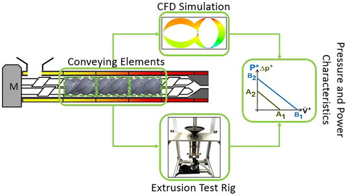
Hot melt extrusion by a co-rotating twin screw extruder is an important process in the pharmaceutical industry. Especially for quality by design aspects, a comprehensive process understanding is indispensable. The performance of conveying elements was determined as critical process parameter, and therefore an experimental and numerical framework was developed to analyze and compare variations. A test rig capable of measuring volume flow, pressure and torque with high accuracy and precision was designed and built. The 3D simulation was performed using computational fluid dynamics (CFD). A stationary model with impulse transmission and an apparent motion of the screws was applied. The experimental data were fitted to the model of Pawlowski, and parameters for the pressure (A1, A2) and power characteristics (B1, B2) were determined. Good agreement between experimental data and the model was observed. The simulation was significantly faster compared to common methods, and the results were consistent with the literature. Systematic investigations of a native and worn screw were performed with CFD resulting in a transport capacity increase and a pressure build up decrease for all tested screw elements. An experimental and simulation setup was generated to assess the performance of co-rotating twin screw elements. The experiments provided high-quality data, and the simulations exhibited high flexibility with low computational effort.
GRAPHICAL ABSTRACT
1. Introduction
Hot melt extrusion using a co-rotating, intermeshing, twin-screw extruder is a promising technology for drug manufacturing that is receiving increasing attention (Patil et al. Citation2016; Simões et al. Citation2019). Next to the production of amorphous solid dispersions to increase the bioavailability of poorly water-soluble drugs (Butreddy et al. Citation2022), there are other forward-looking applications, including taste-masking (Li et al. Citation2022), controlled or modified drug release (Sandhu et al. Citation2022) and stabilization of the active pharmaceutical ingredient (Alzahrani et al. Citation2022). Compared to conventional pharmaceutical processing methods, this technique offers good mixing performance, self-wiping properties due to the intermeshing screws, and solvent-free, rapid, continuous processing (Crowley et al. Citation2007; Zhang et al. Citation2020). The screws usually have a modular design with different elements, which enables a process-specific sequence of unit operations. The most common element types are conveying and kneading elements (Rauwendaal Citation1981). Product quality depends on a detailed understanding of the different unit operations and the influencing process parameters (Wesholowski et al. Citation2018). In pharmaceutical applications, process design by scientifically informed tailoring of the screw configuration is uncommon. However, this should be the focus of research, especially with regard to Quality by Design aspects. This benefits both consumers, through consistently reliable and effective high-quality products, and manufacturers, through traceable quality and reduced cost (Sprenger et al. Citation2013).
One focus of this work is experimental investigations regarding the performance of individual screw elements, which were evaluated in accordance with Pawlowski (Pawlowski Citation1971). His application of similarity theory is valid for a laminar, isothermal flow of a single-phase, Newtonian fluid in a fully filled screw element. The pressure characteristic of a specific screw element is described by a linear correlation between the dimensionless volume flow () (EquationEquation (1)
(1)
(1) ) and the dimensionless pressure (
) (EquationEquation (2)
(2)
(2) ), whereas the power characteristic is described by a linear correlation between the dimensionless power (
) (EquationEquation (3)
(3)
(3) ) and
The dimensionless numbers are derived from correlations between the screw speed (
), the viscosity (
), the screw diameter (
), the length of the screw element (
), the volume flow (
), the pressure difference (
) and the power (
). The intersection with the axis leads to the characteristic parameters A1 and A2 for the pressure, and B1 and B2 for the power (). The corresponding intercept forms are presented in EquationEquations (4)
(4)
(4) and Equation(5)
(5)
(5) and called pressure and power characteristics of a specific screw element, respectively. Different process regimes can be identified such as backward pumping, conveying and overrun.
(1)
(1)
(2)
(2)
(3)
(3)
(4)
(4)
(5)
(5)
Figure 1. Graphical representation of the pressure and power characteristic for specific screw elements, according to (Pawlowski Citation1971).
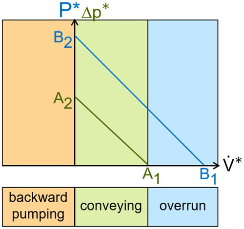
The parameter A1 thus describes the maximum dimensionless, intrinsic throughput of a screw element without an axial pressure gradient and an open die, which is why A1 is also called the conveying parameter. Furthermore, the conveying parameter is specific to the screw geometry and not dependent on process variables (Rauwendaal Citation1981). The characteristic parameter A2 defines the maximum possible pressure build-up of a screw element that can be achieved by a closed die. B1 is the turbine point. If the dimensionless throughput increases above this point, the screw delivers power. The characteristic parameter B2 describes the maximum power of an element, if no throughput is generated (Eitzlmayr et al. Citation2013; Kohlgrüber Citation2019).
Generating sufficient data to analyze the screw elements is both time consuming and costly, so simulation techniques are an important tool to obtain meaningful data in a short time. Modeling offers the possibility to analyze and predict the interaction between screw configuration and product properties of the complex extrusion process. 1D and 3D models are the most common. A 1D model represents the extrusion process in an axial direction while integrating over the cross section of the process unit. The 3D model, on the other hand, is a detailed model of the extruder in which the processing region is resolved into discrete volume elements, so that even critical locations with high temperature or high shear rate can be investigated. A disadvantage, however, is the high computational effort, since the gap between the screws and the barrel, especially, requires a high resolution of the computational mesh (Eitzlmayr et al. Citation2014; Durin et al. Citation2014).
One focus of this work is on 3D modeling of the behavior of different screw elements in a twin-screw extruder evaluating transport capacity, pressure build up and power consumption.
Various approaches of 3D CFD modeling of screw machines are known (Hyvärinen et al. Citation2020; Kumar and Arumugam Citation2020; Dong et al. Citation2020). A mesh-free approach is smoothed-particle hydrodynamics (SPH), which based on the Lagrangian particle method (Eitzlmayr and Khinast, Citation2015; Eitzlmayr and Khinast, Citation2015; Robinson and Cleary Citation2019; Bauer et al. Citation2021). In SPH simulations, the fluid to be simulated is divided into a finite number of particles. Each particle is assigned its own physical properties such as mass, density and pressure, and each quantity is obtained for the entire fluid by summing all elements (Bonet and Lok Citation1999). Common, mesh-based discretization approaches are the Finite Element Method (FEM) (Ishikawa et al. Citation2000; Ishikawa et al. Citation2002; Malik and Kalyon Citation2005) and the Finite Volume Method (FVM) (Mours et al. Citation2022). Mesh-based CFD analysis offers the possibility of modeling the entire geometry, with screws and barrel in time-dependency of the rotating screws. In order to represent the time dependency, the simulations for the individual time steps are carried out and merged, so that a quasi-steady-state simulation can be assumed (Bravo et al. Citation2000; Kalyon and Malik Citation2007; Malik et al. Citation2014). Another method avoiding time consuming remeshing for rotating screws is the Mesh Superposition Technique (FEM method), where two overlapping, non-deformed meshes (one for the volume inside the barrel and one for the rotating screws) are needed (Ficarella et al. Citation2006; Barrera et al. Citation2008). Another meshing strategy deals with dynamic meshes and allows for remeshing of deformed mesh areas caused by the screw rotation (Tagliavini et al. Citation2018). Here, the screws rotate as rigid bodies, which exerts an impulse on the surrounding fluid volume. The generation of such grids is very complex, as the meshing in narrow regions is difficult and the dynamic grid is re-meshed with each movement. In terms of simulation, such an approach requires high computing power.
The aim of this study was to characterize conveying elements used in the hot melt extrusion process with respect to their transport capacity, pressure build up and power consumption. Therefore, a test rig was designed and qualified for an accurate measurement of critical process variables such as screw speed, volume flow, pressure difference and torque. Furthermore, a complex fluid dynamic simulation was established using an impulse transmission method, in order to predict the performance of individual screw elements without experimental data (Bravo et al. Citation2000). The results of the experimental data were used to validate the numerical simulation.
2. Materials and methods
2.1. Materials
In the context of this work, the silicone oil Wacker 10000 (AK 10000, Drawin Vertriebs GmbH, Riemerling, Germany) was used as received. This Newtonian fluid has a density of 0.97 g/cm3 at 25 °C and a viscosity of 9.7 Pa s in accordance with the product specifications (WACKER® AK 10000, Citation2022).
2.2. Experimental determination of screw parameters
Three double-flighted conveying elements from Leistritz (ZSE27 Maxx, Leistritz, Nuremberg, Germany) were characterized with respect to dimensionless volume flow, dimensionless pressure and power parameters. The characteristics of these elements depend on the pitch of the elements (see , Leistritz notation, first column). The geometric data of these elements were measured precisely. The elements have a diameter of 28.2 mm, and the screw center distance is 23.0 mm with a gap of 0.2 mm between the screws and the barrel. The ratio between the inner and outer diameter is 1.65.
Table 1. Notation for the three conveying elements (GFA) used in this investigation.
2.3. Numerical determination of screw parameters
The simulation was carried out with the simulation software ANSYS Fluent 2020R1 (ANSYS Inc., Headquarters: Pennsylvania, USA, 1994), which is designed for flow simulations, based on the Navier-Stokes equations. A laminar, isothermal and incompressible flow was assumed. For the meshing, a wall distance of 4 cells was set. Furthermore, tetrahedral cells and, additionally, the function "sizing" at the die were used. The mesh refinement can be seen in and in . When selecting the boundary conditions, the inlet was defined as inlet-vent and the outlet as pressure-outlet. This generated an inlet at atmospheric pressure with no backflow through the inlet plane, and an outlet at atmospheric pressure. In addition, the surfaces of the screw elements and the screw tip were forced to rotate as a rotating wall with a rotational speed of 20 rpm for three different die diameters (2, 4, 6 mm). With this method, an impulse on the fluid from the screw element in the direction of rotation was modeled to simulate the rotation of the screws and conveying of material to the die. All simulations were calculated using a pressure-based solver with a semi-implicit method for pressure-linked equations. Here, a relationship between velocity and pressure corrections, to enforce mass conservation and to obtain the pressure field, were used. A second-order discretization was set for the pressure and momentum to reduce the risk of numerical diffusion. All presented simulations were carried out in steady state without a dynamic mesh.
Figure 2. Mesh quality for the screw element GFA-2-30-30 with a 4 mm die.
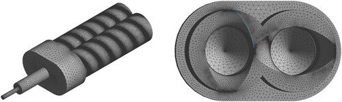
Table 2. Mesh quality for the conveying elements.
The orthogonality for all elements is around 0.76, and the aspect ratio around 15.5. The number of mesh elements and nodes ranges between 10 and 17 million ().
3. Results and discussion
3.1. Design of the test rig
The performance (transport capacity, pressure build up and power consumption) of the individual screw elements was determined using a specially-designed test rig. This was required, since particularly low torque values and pressure differences were expected (Eitzlmayr et al. Citation2013), which cannot be measured reliably on a production scale extruder capable of running at 40 kg/h. Therefore, commercial screw elements () were placed in an acrylic extrusion barrel (Glacryl Hedel GmbH, Ansbach, Germany) of eight times the screw diameter (8D), using the same geometry and clearances as the commercial one. A transparent material was chosen for visual inspection of the extrusion process, which was characterized by a lack in temperature and abrasion resistivity. Since silicon oils were intended to be used, these shortcomings were accepted. A vertical alignment was preferred to remove air bubbles from the process throughout the material inlet and avoid additional pumps, in order to reduce the complexity. The drive unit (, left, A) consists of a stepper motor (iHSS86-60-45, Sorotex GmbH, Rheinmuenster, Germany) capable of applying 4.5 Nm torque and a maximum speed of 50 rpm, as well as a belt transmission (Antriebstechnik, Maedler GmbH, Duesseldorf, Germany) to distribute the motion evenly to both screw shafts (Dold Mechatronik, Haslach, Germany). One of the two screw shafts was equipped with a torque sensor (DR2112, Lorenz Messtechnik GmbH, Alfdorf, Germany) with an operating range up to 10 Nm and an additional screw speed measurement (, left, B). This device is quite sensitive and delicate to work with, but this low measuring range was required to characterize short screw sections (8D) (Liesenfelder Citation2008).
Figure 3. Design of the test rig: entire setup (left), process unit (right).
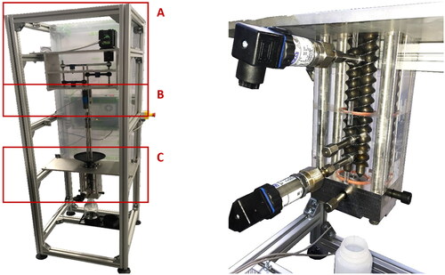
The process unit consisted of a material inlet attached to the extrusion barrel and a die (, left, C). Two pressure sensors (S-11, Wika, Klingenberg, Germany) at distinct points on the extrusion barrel were utilized, operating up to 4 MPa. Multiple cylindrical dies of 2, 4 and 6 mm diameter, and 20 mm length, were used at the barrel outlet to alter the process conditions. A flask and a scale (MSE2203S-100-DR, Satorius, Goettingen, Germany) were used to measure the subsequent volume flow based on material density.
3.2. Qualification of the test rig
The newly developed experimental setup was qualified with respect to the geometry of the extrusion barrel and die. This was identified as the main parameter of influence for the characterization of the screw elements (Matić et al. Citation2019). Changes were expected due to material wear and deformation from mechanical stresses, but no effects were observed. This was related to the gentle process conditions using silicon oil. The different sensors for measuring the screw speed, volume flow, pressure and torque were calibrated according to the ICH Q2 R1 (ICH Citation1994). This accounted for the linearity, measuring range, accuracy, and reproducibility. Representative data for the linearity and precision determination of the pressure and the torque sensor are given in . The linearity was investigated in up to 130% of the expected nominal value which was up to 0.12 MPa in terms of pressure and up to 1.25 Nm for torque. The reproducibility was assessed using the standard deviation and confidence interval.
Figure 4. Representative example of linearity for pressure (left) and torque (right) according to ICHQ2 R1 (n = 3).
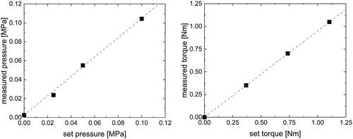
The linearity of the pressure and torque calibration () was high, as indicated by a particularly high coefficient of determination of 0.9998 and 0.9999, respectively. Slight deviations to the manufacturer calibrations and the reference were seen, indicated by the deviation of the coefficient of regressions to 1. In terms of the pressure sensors, slight deviations (smaller than 2%) were seen between both sensors, but the calibration to the reference (S-11, Wika, Klingenberg, Germany) was subsequently used. Calibrated weights, used as a reference for the torque sensor, were attached to the sensor by a pulley and string. The calibrations were checked periodically during the course of this study. The linearity measurements were repeated three times for each point. The intermediate precision of the repetition measurements is appropriate considering the small range, and is less than 2%.
3.3. Experimental determination of screw parameters
The performance of the individual screw elements was characterized in accordance with Pawlowski (Citation1971) by four dimensionless numbers (A1, A2, B1, B2) called screw parameters. Therefore, measurements were performed in the test rig by varying the die diameter (2, 4, 6 mm) using a constant screw speed of 20 rpm. The three tested conveying screw elements exhibited different screw characteristics (). Subsequently, a linear regression was performed to determine the screw parameters ().
Figure 5. Pressure (left) and power (right) characteristics for the conveying elements determined experimentally (n = 5).
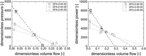
Table 3. Characteristic screw parameters for the conveying elements determined experimentally and compared with literature data.
These experiments were repeated at least five times independently from each other. The individual regression lines of the different screw elements show distinctive differences, while steeper slopes are observed with lower screw pitch. This is consistent with the literature, where lower pitches show higher pressure build up, higher power consumption and lower volume flow (Eitzlmayr et al. Citation2013). According to Pawlowski, the regression lines can be expressed by intercept forms, where the slope is transformed in a zero point, A1 and B1, respectively (EquationEquations (4)(4)
(4) and Equation(5)
(5)
(5) ). There has always been a debate in the pharmaceutical community about using extrapolated values since they are prone for high errors. However, the extrapolated screw parameters (A1, A2, B1, and B2) are not used as individual values but as parameters to describe a linear function, like slope and intercept. These functions were used in model evaluations, and depending on the applied volume flow, no extrapolation was performed.
Comparing individual screw elements to each other or to data from the literature shows that screw parameters can be used rather comparing the pressure and power characteristics themselves. However, even if conveying elements are uniquely defined by three parameters (screw diameter, ratio between outer and inner diameter, and pitch) (König Citation2008) the clearance between screw and barrel as well as the center distance must be considered. These crucial parameters change with respect to equipment use due to wear and are usually not specified in literature adequately. A rather complete description was provided by König, which serves for comparison since the geometries were similar () (König Citation2016).
The experimentally determined, characteristic parameters, A1 and A2, fit quite nicely with the literature data, as they are close to literature values and show similar behavior with respect to changes in the screw pitch as literature values. The characteristic parameters of the power, B1 and B2, are different but the same order of magnitude as the literature values. The differences can be attributed to the gap between screws and barrel, which is not known here and has a definite influence.
3.4. Numerical determination of screw parameters
Complementary to experimental investigations of the characteristic screw parameters, complex fluid dynamic simulations were performed, both to minimize the high experimental effort and to investigate parameters not accessible experimentally. Frequently, a dynamic mesh is used for this type of investigation, which is computationally expensive. In this study, therefore, the impulse transmission method with a static mesh was applied, where the screws do not rotate. Instead, momentum is transferred from the screw to the material, causing material motion. The shortcoming of this method is that temperature gradients and shear in the gap cannot be resolved as accurately as is possible with remeshing methods. However, it comes with particularly low computational effort and should be sufficient to capture the pressure and power characteristics of the screw elements (Bravo et al. Citation2000; Raut et al. Citation2003; Kalyon and Malik Citation2007).
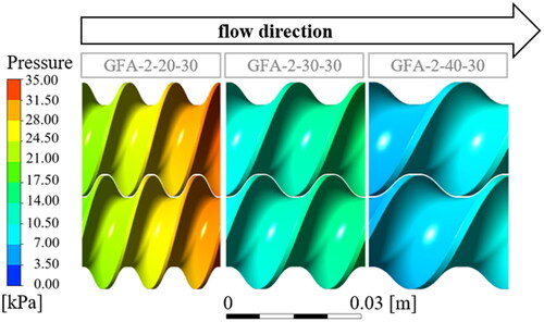
A first impression of the simulation results can be obtained from , where the material pressure at the screw surface is given. An axial pressure gradient was noticed for all screw elements increasing in the flow direction. This observation was expected, since conveying elements with a positive transport capacity were utilized. Moreover, the pressure rise decreases with increasing screw pitch, which is consistent with the literature (Bierdel Citation2008).
Figure 6. Pressure build-up of the three conveying elements with a 2 mm die. GFA-2-20-30 (left), GFA-2-30-30 (Middle) and GFA-2-40-30 (right).
The simulation results were evaluated similarly to the experimental data in order to allow a direct comparison. Repetitions were not included since no stochastic variability was added to the simulation. Therefore the same results were expected for each repetitive simulation run. The linearity of the pressure and power characteristics was perfect, which was inherent to the complex fluid dynamic simulation. Based on this, only two different flow rates had to be simulated in order to derive the specific pressure and power characteristics for each individual screw element, but in this study, three operating conditions were considered ().
Figure 7. Pressure and power characteristics of the conveying elements determined by simulation.
Generally, the pressure and power characteristics are quite similar between simulation and experiments. The overall course of the functions is the same, and the relative position of the individual functions with respect to each other fits as well ( and ). However there are slight differences considering the absolute values ( and ). These are attributed to the flow simulations using the impulse transmission method, allowing a rapid calculation (less than 5 h on a desktop computer). This approach, with a stationary domain and a rotating wall as a boundary condition, ignores the normal component of the wall motion (Hobeika and Sebben Citation2018) and, therefore, predicts a lower volume flow.
Table 4. Pressure and power parameters of the conveying and kneading elements determined by simulation.
3.5. Application of the simulation
The simulation can be considered as a valuable option for formulation and process development. Moreover it can be seen as a tool to study the process and look into properties that are measureable only with high experimental effort, if at all. In order to elucidate this further, the simulations were used to investigate the wear of extrusion screws, so the screw diameters were set from the “native” (28.2 mm) to the lower limit given by the manufacturer (27.2 mm) and called “worn” ().
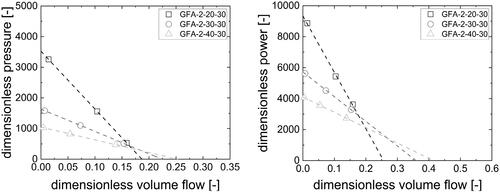
Figure 8. Comparison of the pressure (left) and power (right) characteristics determined by simulation for a native screw element and for a worn screw element.
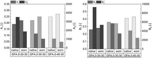
Based on the above mentioned limitations of the impulse transmission method, a deviation in the screw parameters between experiment and simulation was expected. However, comparisons of the native and worn elements, as well as a comparison between different screw elements, were possible. The transport capacity (A1, conveying parameter) increases with the screw wear, which is consistent with the literature (Kohlgrüber Citation2020). This occurs because the volume of the barrel increases as the screw becomes worn, thus increasing the transport capacity for the material. The clearance between screw and barrel is also rather small (0.7 mm) for the worn screws considering the high viscosity of the silicon oil. In this respect, the energy transfer from the screw to the material is not constrained, and there are no dead zones between barrel and screw. When considering the pressure build up parameter (A2), the screw wear leads to distinctly lower values. This is likely to occur based on a more pronounced leak flow in the larger gap between barrel and screws, which is moving counter to the material flow in the extruder.
The B1 parameter is determined at the so-called turbine point, where the material volume flow corresponds to the volume transport capacity of the screw, so no power is dissipated or gained from the material transport. This parameter is not affected by the screw wear, since the transport capacity of the screw is not changing, practically speaking, due to the minor shrinkage of the screw. The maximum power a screw element is capable of applying (B2) decreases with the screw wear. This is attributed to the lower pressure build up (A2) and the lower power consumption in this respect. Based on the results, it is evident that the simulation can be used to make a reliable prediction about the process parameters of screw elements in a short time as compared to experiments. This makes it possible to assess whether they are still suitable for use or whether changes to important parameters that are not compatible with the process are to be expected due to wear. The simulations are able to be applied to new screw elements to predict their behavior. It is therefore a good tool for better process understanding and product quality.
4. Conclusion
The aim of this study was to determine the performance of screw elements of a co-rotating, intermeshing, twin-screw extruder. Three conveying elements with pitches of 20, 30 and 40 mm were investigated with respect to their behavior. For this purpose, a test rig was designed, which is geometrically similar to the Leistritz ZSE27 MAXX. To ensure an accurate, small-scale measurement, sensors for determining screw speed, pressure difference and torque were installed and calibrated according to ICH Q2. The results fit to the model of Pawlowski and characteristic parameters for all three screw elements were obtained.
Since these experiments are time-consuming and cost-intensive, a 3D, CFD simulation was developed in addition to the newly-designed test rig. This is based on the impulse transmission method. Here, an apparent movement of the screws by applying a velocity to the fluid is used to simulate the screw rotation. This approach can generate data in a short time without a dynamic mesh and with low computational effort. Even if there are some limitations to this technique, it provides a good approximation.
The results of the experimental data were compared to the numerical simulation and can serve as validation. Thus, new screw elements can be characterized directly, or currently used elements can be investigated in order to characterize their behavior and thus make important predictions about the process. This will enable understanding of crucial sub-processes like mixing and thermal degradation, which are relevant for pharmaceutical products.
| Nomenclature | ||
| A1, A2 | = | dimensionless pressure parameters |
| B1, B2 | = | dimensionless power parameters |
| D, Da, Di | = | screw diameter, a = outer, i = inner [m] |
| L | = | screw length [m] |
| n | = | screw speed [1/s] |
| p | = | pressure [Pa] |
| = | dimensionless pressure | |
| P | = | power [W] |
| P* | = | dimensionless power |
| = | volume flow [m3/s] | |
| = | dimensionless volume flow | |
| = | viscosity [Pa s] | |
Disclosure statement
The authors declare no conflict of interest.
Additional information
Funding
References
- Alzahrani A, Nyavanandi D, Mandati P, Youssef AAA, Narala S, Bandari S, Repka M. 2022. A systematic and robust assessment of hot-melt extrusion-based amorphous solid dispersions: theoretical prediction to practical implementation. Int J Pharm. 624:121951. doi: 10.1016/j.ijpharm.2022.121951.
- Barrera MA, Vega JF, Martínez-Salazar J. 2008. Three-dimensional modelling of flow curves in co-rotating twin-screw extruder elements. J Mater Process Tech. 197(1–3):221–224. doi: 10.1016/j.jmatprotec.2007.06.028.
- Bauer H, Matić J, Khinast J. 2021. Characteristic parameters and process maps for fully-filled twin-screw extruder elements. Chem Eng Sci. 230:116202. doi: 10.1016/j.ces.2020.116202.
- Bierdel M. 2008. Computational fluid dynamics. In: K. Kohlgrüber, editor. Co-rotating twin-screw extruders. Munich, Germany: Carl Hanser Publishers, p. 139–158.
- Bonet J, Lok T-S. 1999. Variational and momentum preservation aspects of smooth particle hydrodynamic formulations. Comput Meth Appl Mech Eng. 180(1–2):97–115. doi: 10.1016/S0045-7825(99)00051-1.
- Bravo V, Hrymak A, Wright J. 2000. Numerical simulation of pressure and velocity profiles in kneading elements of a co‐rotating twin screw extruder. Polym Eng Sci. 40(2):525–541. doi: 10.1002/pen.11184.
- Butreddy A, Sarabu S, Almutairi M, Ajjarapu S, Kolimi P, Bandari S, Repka MA. 2022. Hot-melt extruded hydroxypropyl methylcellulose acetate succinate based amorphous solid dispersions: impact of polymeric combinations on supersaturation kinetics and dissolution performance. Int J Pharm. 615:121471. doi: 10.1016/j.ijpharm.2022.121471.
- Crowley MM, Zhang F, Repka MA, Thumma S, Upadhye SB, Battu SK, McGinity JW, Martin C. 2007. Pharmaceutical applications of hot-melt extrusion: part I. Drug Dev Ind Pharm. 33(9):909–926. doi: 10.1080/03639040701498759.
- Dong T, Jiang S, Wu J, Liu H, He Y. 2020. Simulation of flow and mixing for highly viscous fluid in a twin screw extruder with a conveying element using parallelized smoothed particle hydrodynamics. Chem Eng Sci. 212:115311. doi: 10.1016/j.ces.2019.115311.
- Durin A, De Micheli P, Nguyen HC, David C, Valette R, Vergnes B. 2014. Comparison between 1D and 3D approaches for twin-screw extrusion simulation. Int Polym Proc. 29(5):641–648. doi: 10.3139/217.2951.
- Eitzlmayr A, Khinast J, Hörl G, Koscher G, Reynolds G, Huang Z, Booth J, Shering P. 2013. Experimental characterization and modeling of twin‐screw extruder elements for pharmaceutical hot melt extrusion. AICHE J. 59(11):4440–4450. doi: 10.1002/aic.14184.
- Eitzlmayr A, Khinast J. 2015. Co-rotating twin-screw extruders: detailed analysis of conveying elements based on smoothed particle hydrodynamics. Part 1: hydrodynamics. Chem Eng Sci. 134:861–879. doi: 10.1016/j.ces.2015.04.055.
- Eitzlmayr A, Khinast J. 2015. Co-rotating twin-screw extruders: detailed analysis of conveying elements based on smoothed particle hydrodynamics. Part 2: mixing. Chem Eng Sci. 134:880–886. doi: 10.1016/j.ces.2015.05.035.
- Eitzlmayr A, Koscher G, Reynolds G, Huang ZY, Booth J, Shering P, Khinast J. 2014. Mechanistic modeling of modular co-rotating twin-screw extruders. Int J Pharm. 474(1–2):157–176. doi: 10.1016/j.ijpharm.2014.08.005.
- Ficarella A, Milanese M, Laforgia D. 2006. Numerical study of the extrusion process in cereals production: part I. Fluid-dynamic analysis of the extrusion system. J Food Eng. 73(2):103–111. doi: 10.1016/j.jfoodeng.2004.11.034.
- Hobeika T, Sebben S. 2018. CFD investigation on wheel rotation modelling. J Wind Eng Ind Aerodyn. 174:241–251. doi: 10.1016/j.jweia.2018.01.005.
- Hyvärinen M, Jabeen R, Kärki T. 2020. The modelling of extrusion processes for polymers—a review, polymers, 12. Polymers (Basel). 12(6):1306. doi: 10.3390/polym12061306.
- ICH. 1994. ICH. Q2(R1)—validation of analytical procedures.
- Ishikawa T, Amano T, Kihara SI, Funatsu K. 2002. Flow patterns and mixing mechanisms in the screw mixing element of a co-rotating twin-screw extruder. Polym Eng Sci. 42(5):925–939. doi: 10.1002/pen.11002.
- Ishikawa T, Kihara SI, Funatsu K. 2000. 3-D numerical simulations of nonisothermal flow in co-rotating twin screw extruders. Polym Eng Sci. 40(2):357–364. doi: 10.1002/pen.11169.
- Kalyon D, Malik M. 2007. An integrated approach for numerical analysis of coupled flow and heat transfer in co-rotating twin screw extruders. Int Polym Proc. 22(3):293–302. doi: 10.3139/217.1020.
- Kohlgrüber K, Bierdel M, Rust H. Polymer-Aufbereitung und Kunststoff-Compoundierung Grundlagen. Apparate, Maschinen, Anwendungstechnik.
- Kohlgrüber K. 2019. Co-rotating twin-screw extruders: fundamentals. In: K. Kohlgrüber, editor. Co-rotating twin-screw extruders: fundamentals. Munich: Carl Hanser Verlag GmbH Co KG.
- Kohlgrüber K. 2020. Conveying behavior, pressure and performance behavior. In: K. Kohlgrüber, editor. Co-rotating twin-screw extruders: fundamentals. Munich: Carl Hanser Verlag.
- König T. 2008. Geometry of the co-rotating extruders: conveying, and kneading elements. In: K. Kohlgrüber, editor. Co-rotating twin-screw extruders. Munich: Carl Hanser Verlag.
- König T. 2016. Förder- und Leistungsparameter von üblichen Förderelementen. In: K. Kohlgrüber, editors. Der gleichläufige Doppelschneckenextruder. Munich: Carl Hanser Verlag.
- Kumar P, Arumugam S. 2020. Non-Newtonian and non-isothermal numerical modelling of a twin screw hydrogen extruder with slip imposed boundary condition on the screw surface. Fusion Eng Des. 161:111896. doi: 10.1016/j.fusengdes.2020.111896.
- Li J, Li C, Zhang H, Gao X, Wang T, Wang Z, Zheng A. 2022. Preparation of azithromycin amorphous solid dispersion by hot-melt extrusion: an advantageous technology with taste masking and solubilization effects. Polymers (Basel). 14(3):495. doi: 10.3390/polym14030495.
- Liesenfelder U. 2008. Pressure generation and energy input in the melt. In: K. Kohlgrüber, editor. Co-rotating twin-screw extruders. Munich: Carl Hanser Verlag.
- Malik M, Kalyon D. 2005. 3D finite element simulation of processing of generalized Newtonian fluids in counter-rotating and tangential TSE and die combination. Int Polym Proc. 20(4):398–409. doi: 10.1515/ipp-2005-0068.
- Malik M, Kalyon DM, Golba JC. 2014. Simulation of co-rotating twin screw extrusion process subject to pressure-dependent wall slip at barrel and screw surfaces: 3D FEM analysis for combinations of forward- and reverse-conveying screw elements. Int Polym Proc. 29(1):51–62. doi: 10.3139/217.2802.
- Matić J, Witschnigg A, Zagler M, Eder S, Khinast J. 2019. A novel in silico scale-up approach for hot melt extrusion processes. Chem Eng Sci. 204:257–269. doi: 10.1016/j.ces.2019.04.016.
- Mours M, Reinelt D, Wagner H-G, Gilbert N, Hofmann J. 2022. Melt conveying in co-rotating twin screw extruders: experiment and numerical simulation. Int Polym Proc. 15(2):124–132. doi: 10.1515/ipp-2000-0003.
- Patil H, Tiwari RV, Repka MA. 2016. Hot-melt extrusion: from theory to application in pharmaceutical formulation. Aaps Pharmscitech. 17(1):20–42. doi: 10.1208/s12249-015-0360-7.
- Pawlowski J. 1971. Die Ähnlichkeitstheorie in der physikalisch-technischen Forschung: grundlagen und Anwendung. Berlin: Springer-Verlag.
- Raut JS, Naik VM, Jongen TR. 2003. Efficient simulation of time‐dependent flows: application to a twin screw extruder. AICHE J. 49(8):1933–1946. doi: 10.1002/aic.690490803.
- Rauwendaal CJ. 1981. Analysis and experimental evaluation of twin screw extruders. Polym Eng Sci. 21(16):1092–1100. doi: 10.1002/pen.760211608.
- Robinson M, Cleary PW. 2019. Effect of geometry and fill level on the transport and mixing behaviour of a co-rotating twin screw extruder. Comp Part Mech. 6(2):227–247. doi: 10.1007/s40571-018-0210-y.
- Sandhu H, Vaka SRK, Desai D, Jariwala P, Railkar A, Phuapradit W, Shah N. 2022. Hot‐melt extrusion technology for modified‐release (MR) formulation development, oral drug delivery for modified release formulations. 181–204.
- Simões MF, Pinto RM, Simões S. 2019. Hot-melt extrusion in the pharmaceutical industry: toward filing a new drug application. Drug Discov Today. 24(9):1749–1768. doi: 10.1016/j.drudis.2019.05.013.
- Sprenger K, Nickerson D, Meeker-O'Connell A, Morrison BW. 2013. Quality by design in clinical trials: a collaborative pilot with FDA. Ther Innov Regul Sci. 47(2):161–166. doi: 10.1177/0092861512458909.
- Tagliavini G, Solari F, Montanari R. 2018. CFD simulation of a co-rotating twin-screw extruder: validation of a rheological model for a starch-based dough for snack food. Int J Food Eng. 14(2):1–13. doi: 10.1515/ijfe-2017-0116.
- WACKER® AK 10000. W.C. AG (Ed.), Munich, 2022.
- Wesholowski J, Berghaus A, Thommes M. 2018. Inline determination of residence time distribution in hot-melt-extrusion. Pharmaceutics. 10(2):49–59. doi: 10.3390/pharmaceutics10020049.
- Zhang P, Shadambikar G, Almutairi M, Bandari S, Repka MA. 2020. Approaches for developing acyclovir gastro-retentive formulations using hot melt extrusion technology. J Drug Deliv Sci Tec. 60:Article 102002. doi: 10.1016/j.jddst.2020.102002.