Abstract
A pleated filter bag is often used to treat exhaust gas in many industrial applications, due to its fairly high dust collection efficiency and relatively low pressure drop. This work deals with the optimum pleating geometries of a pleated filter made with a newly developed PTFE/glass composite filter. It was found that pleating geometries, including pleat height and pleat pitch, directly affect the cleaning efficiency. The design index, α, which stands for the ratio of pleat height to pleat pitch, is 1.48 for optimum operation. When the α value was higher than 1.48, the pressure drop across the pleated filter medium increased, resulting in a decreased cleaning interval due to the difficulty of filter cleaning. Therefore, it is necessary that the optimum pleating geometry should be determined by employing the dimensionless parameter, α, in the design of cartridge filters.
A pleated filter bag is often used to treat exhaust gas in many industrial applications due to its fairly high dust collection efficiency and relatively low pressure drop. The present paper introduces an optimum design configuration to make a pleated filter with newly developed PTFE/glass composite filter media. A dimensionless parameter that is the ratio of pleat height to pleat pitch should be considered to make the best quality pleated filter.
Introduction
A bag house is an air pollution control device (APCD) widely used to remove particulate matters in flue gas due to its high removal efficiency and good applicability. In general, cylindrical filter bags that are installed perpendicularly in a bag house are usually applied. This system has an advantage in that it can maximize the usage of the inner space.
As particulate matter is collected in a filter bag, the pressure drop across the filter medium increases. The filters should be regenerated in order to achieve the desired collection performance when the pressure drop reaches a maximum allowable value. One of the typical technologies that allow filters to be regenerated is pulse-jet cleaning, which injects jet air from the inside to the outside of the filter. This method can achieve filter cleaning and regeneration at the same time by continuously treating the flue gas in the bag house. However, the cleaning efficiency highly depends on the filter geometry (CitationLo et al., 2010). Recently, interest in a pleated filter has been getting higher in terms of the aspects of increasing the treating capacity of exhaust gas and decreasing the installation space of the bag house (CitationChen et al., 1995; CitationWang, 2009). The cleaning interval of a pleated filter bag can be increased more than twice at the same flow rate, and filter lifetime can also be increased, because a pleated filter has approximately two to four times the filtration area of a cylindrical filter with the same dimensions. Additionally, the number of filter bags can be decreased when we apply pleated filter bags in exhaust gas with a certain gas flow rate, resulting in a decrease of the necessary system installation space. In spite of these various advantages, research into pleated filters has been limited to air filters for cleaning up indoor air in vehicles and external flows into an industrial gas turbine (CitationWakeman et al., 2005). There have been some experimental and numerical studies about HEPA/ULPA filters that have investigated the filtration and filter resistance properties of pleated filter media with various geometrical configurations (CitationCho et al., 1994; CitationDel Fabbro et al., 2002; CitationFotovati et al., 2011; CitationLee et al., 1991). However, it is quite difficult to apply these findings to a bag house system. In other words, initial pressure drop and collection efficiency are the most critical parameters in HEPA/ULPA filters applied to low dust loading. On the other hand, dust collection efficiency and residual pressure drop are more important factors in a bag house system. Therefore, various experimental studies are needed to apply a pleated filter bag to a pulse-jet cleaning bag house system and to replace cylindrical filters with pleated filters in industrial applications with harsh environments.
We attempted to figure out the optimum design configuration needed to pleat previously developed PTFE/glass composite filter media in this work. The PTFE/glass composite filter, which consists of a PTFE film that is 0.1 mm thick and a glass mat that is 0.8 mm thick, was made by a foam coating method. This filter has excellent thermal resistance and a high filtration performance (CitationPark et al., 2010).
Experimental
Materials
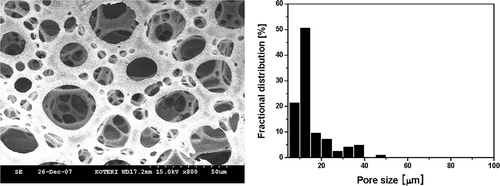
shows the porous surface structure and the pore size distribution of the PTFE/glass composite filter, which demonstrates a three-dimensional porous structure. We can see that the pores in the tested filter were distributed at under 50 μm in size, and that their mean size was 17 μm. Dust particles may clog the spatial pore channels across the filter medium during filtration.
Air permeability across the porous filter media was calculated by Equationeq (1), which is based on Darcy's law:
where Δp is the pressure drop across the filter medium, μ is the flow viscosity (1.81 × 10⁻⁵ Pa-s at 20°C), v is the filtration velocity, L is the filter thickness, and K is the air permeability of the filter. Thus, the air permeability K is defined as ((μ × v × L)/Δp) which is thereby influenced by physical properties such as flow condition and filter geometry (CitationSeville, 1997).
Pleating method of a filter medium
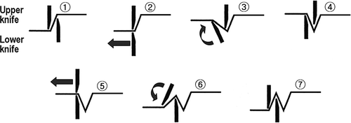
The test composite filter was pleated with a knife pleater, which is generally used in the filter manufacturing process (CitationHutten, 2007). As can be seen in the sequential process shown in , a set of upper and lower knives was placed on the top surface and the back side of the filter medium. The knives independently work to fold the filter medium in the order of to , resulting in a pleated filter. In order to prevent the deformation of pleats by the flue gas stream during filtration, the medium was supported by a stainless-steel wire mesh.
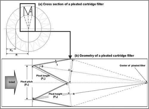
The test filters were prepared with regular pleat lengths (15 mm, 20 mm, 25 mm). The prepared cartridge filter was 273 mm in length and 115 mm in outer diameter. The pleat angles, θ, were 13.3°, 15.6°, and 18.6°. shows a schematic configuration of a pleated cartridge filter, including the pleat angle and the pleat pitch between a pleat and a neighboring pleat.
PL is the pleat length of a sloped plane from a vertex of a pleat mountain to a pleat bottom; PH is the vertical distance from a vertex of a pleat mountain to the inner surface of a pleated filter; and PP is the distance between vertexes of the pleat mountains. In addition, N is the number of pleats, and R is the radius of a pleated filter (57.5 mm). Filter thickness, t, was 0.9 mm. Test filter media were regularly pleated with a pleat angle θ, and the pleat mountain was formed perpendicularly to the flow direction.
Filtration test
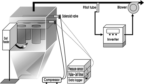
Test filters were characterized in terms of filter cleaning efficiency using an experimental rig, as shown in Four cartridge-type filters were installed in a bag house system that consists of a dust generation part with a dust feeder, a filter cleaning part (compressor pulse jet), a dust collection part (bag house), and a blower. For filter cleaning, high-pressure jet air supplied into blow tubes was periodically injected through independently arranged nozzles controlled by two solenoid valves.
Fly ash particles procured from a local coal-fired power plant were used as the test dust, of which the mean size was 0.76 μm. Filtration velocity, v, was 3 m/min; feeding dust concentration, Ci , was 5.7 g/cm3; jet pressure was 4 kgf/cm2. The air flow rate was measured by a pitot tube and constantly maintained by an inverter control regardless of the increase of pressure drop in the bag-house system. The maximum allowable pressure drop in the bag house was set to 100 mm H2O. Filter cleaning was automatically carried out whenever the pressure drop in the bag house reached the maximum allowable pressure drop.
Results and Discussion
Design parameters to make a pleated filter are the number of pleats, pleat height, pleat pitch, and so forth. These parameters influence the cleaning efficiency of a pleated filter during continuous filtration. The number of pleats is closely related to the filtration area, filtration velocity, and pressure drop. This work focuses on the residual pressure drop immediately after periodic jet back-flushing.
Correlation of pleating parameters
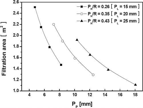
shows the filtration area of the pleated cartridge filters with various pleat pitches, PP , and pleat heights, PH . Larger filtration area was found at narrower pleat pitch and higher pleat height. Such a design may provide more relevant filtration conditions, which can lead to large specific filtration area, resulting in less pressure resistance at the same flow rate. However, a steep angle, θ, with a deep valley may deteriorate the filter cleaning efficiency by air back-flushing. As mentioned earlier, the pleated cartridge filter was constantly pleated with the given angle, θ, and the pleat mountain was formed perpendicularly to the flow direction.
EquationEquations (2) and Equation(3) correlate the conceptual parameters. Pleating parameters calculated by the equations are listed in . The number of pleats was determined by the value of θ (15.6–23.0°) and was 20 to 65 in the manufacturing conditions in this work. Consequently, the filtration area increased with an increasing number of pleats.
Table 1. Relationships Among Pleating Parameters
Evaluation of filter cleaning efficiency
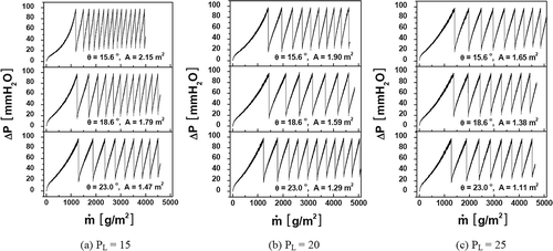
shows the change in pressure drop across the filter medium that was observed as a function of areal mass density of dust particles (collected dust mass per unit filter area) at different P L and θ:
Figure 6. Change in pressure drop at different PL and θ (v = 3 m/min, jet pressure = 4 kgf/cm2, Ci = 5.7 g/m3).
where Ci is the dust concentration, v is the filtration velocity, and t is the filtration time.
These graphs help us to understand the influence of PL and θ on the filter cleaning efficiency. As filtration proceeds, the pressure drop is known to continuously increase, because certain amounts of dust are continuously deposited on the filter surface and in the inner pore channels. The system was designed in such as way that upon reaching the allowable pressure drop (100 mm H2O), the jet pressure (4 kgf/cm2) could be injected from the inside to the outside of the pleated filter bags. Test filtration continued until test particles were collected at more than 4000 g/m2 on the filter. The number of back-flushings was counted, along with a simultaneous measurement of the pressure drop. In addition, the residual pressure drop, which appeared right after back-flushing, was also closely examined. We can see in the figures that better filter cleaning can be achieved with longer PL . In particular, despite there being the same value of PL , the cleaning efficiency was different with pleat angles of θ. The highest cleaning efficiency at PL = 15 was found at θ = 23.0°, while efficiency values of PL = 20 and PL = 25 appeared at θ = 18.6° and θ = 23.0°, respectively.
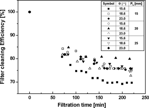
shows the filter cleaning efficiency, ϵ d , as defined in Equationeq (5). It is a relative correlation factor between the residual pressure drop and the initial pressure drop:
where ΔPLo, ΔPHi, and ΔPLi represent the pressure drop of a fresh filter medium without any dust deposit, the highest pressure drop at the i th filtration cycle, which means the maximum allowable pressure drop, and the residual pressure drop right after the ith cleaning, respectively (CitationPark et al., 2010).
Filter cleaning efficiency gradually decreased as dust filtration continuously proceeded. Decreasing rate of cleaning efficiency was not very significant at θ = 18.6o and PL = 20 mm. It was 85% at the first cleaning and almost above 80% even after 4 hours of filtration. On the other hand, the cleaning efficiency was drastically decreased at θ = 15.6o for PL = 15 mm.
We can see in the figure that the effect of θ on the filter cleaning efficiency gets bigger as pleat length increases. That is, when the pleat length was relatively long (PL = 25 mm), the effect of θ on the filter cleaning efficiency was small.
Dimensionless parameter to determine optimum pleating configuration
We need to know the optimum pleating configuration that leads to a good filter cleaning efficiency and high filtration area. Even when a pleated filter has a very high filtration area, a filter with low cleaning efficiency is useless in a bag house system. To determine the best configuration of pleating, we introduced a dimensionless parameter, α (ratio of pleat height to pleat pitch). The parameter α can be rearranged as a function of PH, PL, R, PP , and θ as expressed in Equationeq (6). The calculated values are listed in .
Table 2. Dimensionless Parameter, α, at Various Pleat Geometries
As we can see in , α increases with decreasing pleat angle, θ, and pleat length, PL. The highest value of α = 2.67 was obtained at PL = 15 mm and θ = 15.6°; the lowest value (α = 0.81) was found at PL = 25 mm and θ = 23.0°. The α value is proportional to PH and inversely proportional to PP , as determined in Equationeq (6). Thus, the narrower is the pleat pitch designed, the higher is the α value that obtained. However, we are not sure that a high α value can guarantee high cleaning efficiency even if it provides a high filtration area. Therefore, detailed investigations were conducted to determine the optimum α value.
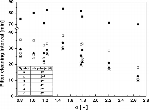
When we evaluate filtration performances in a continuously operating system, cleaning interval is one of the important factors, along with collection efficiency and cleaning efficiency. In other words, higher cleaning efficiency and longer cleaning interval might provide longer filter lifetime for a filtration process using a pleated filter with the same filter medium. shows the filter cleaning interval as a function of α. We can see that the filter cleaning interval is nearly constant at less than α=1.8 and that it decreases with increasing α. In addition, the interval gets shorter and approaches a certain value with the number of cleaning cycles. Through a detailed investigation of the graph, we can see that the highest cleaning efficiency and the most stable cleaning interval, regardless of cleaning cycles, are shown at the configuration of PL = 20 mm, θ = 18.6°.
In conclusion, cleaning efficiency and cleaning interval were optimum when dimensionless parameter, α, was 1.48 [θ = 18.6°, PL = 20 mm]. When the α value was higher than 1.48, the pressure drop across a pleated filter medium was increased, resulting in a decreased cleaning interval due to the difficulty of filter cleaning. Therefore, it is necessary that optimum pleating geometry should be determined by employing this dimensionless parameter, α, in the design of cartridge filters. Pleated bag filters with various sizes and materials have been using in industrial applications. Although we applied a dimensionless parameter, α, to a newly developed PTFE/glass composite filter in this study, this procedure can be adopted as a universal methodology to design pleated filters with various types of filter media. When we design a pleated bag filter, the ratio of pleat height to pleat pitch to be determined by this methodology should be considered.
Conclusions
In order to find an optimum pleating geometry to make a pleated filter using a PTFE/glass composite foam coating filter, various types of pleated filters were manufactured and characterized while controlling pleat angle, pleat length, and number of pleats. The pleated filter had an advantage in that as the number of pleats increases, there are increasing filtration area and increasing flow capacity.
Summarizing the results, we found the optimum pleating configuration through filtration tests of pleated filters with various pleating geometries. The highest cleaning efficiency and best cleaning interval were achieved with a dimensionless parameter, α, of 1.48 [θ = 18.6° and PL = 20 mm]. When the α value was higher than 1.48, the pressure drop across the pleated filter medium increased, resulting in a decreased cleaning interval due to the difficulty of filter cleaning. Therefore, it is necessary that the optimum pleating geometry should be determined by employing the dimensionless parameter, α, in the design of cartridge filters.
Nomenclature
| α | = |
dimensionless parameter for pleating, — |
| Ci | = |
dust concentration, g/cm3 |
| d | = |
distance between points of pleated bottom, mm |
| K | = |
air permeability, m2 |
|
| = |
areal mass density, g/m2 |
| N | = |
number of pleats, each |
| µ | = |
fluid viscosity, Pa-s at 20°C |
| PH | = |
pleat height, mm |
| PL | = |
pleat length, mm |
| PP | = |
pleat pitch, mm |
| R | = |
radius of a bag filter, mm |
| θ | = |
pleat angle, ° |
Acknowledgment
This research was financially supported by the Ministry of Environment of the Republic of Korea under the contract E211-40001-0010-0.
Notes
Myong-Hwa Lee and Sang Bum Kim contributed equally.
References
- Chen , D. , Pui , D.Y.H. and Liu , B.Y.H. 1995 . Optimization of pleated filter designs using a finite-element numerical model . Aerosol Sci. Technol. , 23 : 579 – 590 . doi: 10.1080/02786829508965339
- Cho , S.-J. , Otani , Y. , Emi , H. and Lee , J.-H. 1994 . Characteristics of flow and pressure drop in separator type HEPA filter . Earozoru Kenkyu , 9 ( 1 ) : 51 – 28 .
- Del Fabbro , L. , Laborde , J.C. , Merlin , P. and Ricciardi , L. 2002 . Air flow and pressure drop modeling for different pleated industrial filters . Filtr. Sep. , 39 ( 1 ) : 34 – 40 . doi: org/10.1016/S0015-1882(02)80055-6
- Fotovati , S. , Hosseini , S.A. , VahediTafreshi , H. and Pourdeyhimi , B. 2011 . Modeling instantaneous pressure drop of pleated thin filter media during dust loading . Chem. Eng. Sci. , 66 : 4036 – 4046 . doi: 10.1016/j.ces.2011.05.038
- Hutten , I.M. 2007 . Handbook of Nonwoven Filter Media , Elsevier Ltd .
- Lee , J.-H. , Chung , S.H. , Cho , S.J. and Kim , K.Y. 1991 . A numerical study on pressure drop and flow characteristics in pleated filters . Soc. Air Condition. Refrig. Eng. Korea , 3 ( 3 ) : 176 – 185 .
- Lo , L.-M. , Hu , S.-C. , Chen , D.-R. and Pui , D.Y.H. 2010 . Experimental study of pleated fabric cartridges in a pulse-jet cleaned dust collector . Powder Technol. , 197 : 141 – 149 . doi: org/10.1016/j.powtec.2009.09.007
- Park , B.H. , Kim , S.B. , Lee , M.-H. , Kim , K.S. and Jo , Y.M. 2010 . Preparation and characterization of porous composite filter medium by PTFE foam coating . J. Air Waste Manage. Assoc. , 60 : 137 – 141 . doi: 10.3155/1047-3289.60.2.137
- Seville , J.P.K. 1997 . Gas Cleaning in Demanding Applications. Blackie Academic & Professional , Chapman & Hall .
- Wakeman , R.J. , Hanspal , N.S. , Waghode , A.N. and Nassehi , V. 2005 . Analysis of pleat crowding and medium compression in pleated cartridge filters . Chem. Eng. Res. Des. , 83 ( A10 ) : 1246 – 1255 . doi: org/10.1205/cherd.04183
- Wang , X. 2009 . Simulation and Optimization for Pleated Filter Design , Doctoral thesis, Soongsil University, Republic of Korea .
