Abstract
Automobile shredder residue (ASR) from end-of-life vehicles (ELVs) in Korea has commonly been disposed of in landfills. Due to the growing number of scrapped cars and the decreasing availability of landfill space, effective technology for reducing ASR is needed. However, ASR is a complex mixture, and finding an appropriate treatment is not easy on account of the harmful compounds in ASR. Therefore, research continues to seek an effective treatment technology. However, most studies have thus far been performed in the laboratory, whereas few commercial and pilot studies have been performed. This paper studies the pyrolysis and gasification-melting of ASR. The pyrolyis characteristics have been analyzed in a thermogravimetric analyzer (TGA), a Lindberg furnace, and a fixed-bed pyrolyzer to study the fundamental characteristics of ASR thermal conversion. As a pilot study, shaft-type gasification-melting was performed. High-temperature gasification-melting was performed in a 5000 kg/day pilot system. The gas yield and syngas (H2 and CO) concentration increase when the reaction temperature increases. Gas with a high calorific value of more than 16,800 kJ/m3 was produced in the pyrolyzer. From the gasification-melting process, syngas of CO (30∼40%) and H2(10∼15%) was produced, with 5% CH4 produced as well. Slag generation was 17% of the initial ASR, with 5.8% metal content and 4% fly ash. The concentration of CO decreases, whereas the H2, CO2, and CH4 concentrations increase with an increase in the equivalence ratio (ER). The emission levels of dioxin and air pollution compounds except nitrogen oxides (NOx) were shown to satisfy Korean regulations.
In Korea, automobile shredder residue management has been a big issue. However, ASR has been regarded as a waste, not a useful compound to produce energy. In this study, the authors analyze syngas production of ASR by pyrolysis and high-temperature gasification-melting. The authors can obtain high-quality syngas from the pyrolyzer and gasification-melting system. Notably, gasification-melting has been performed in a 5000 kg/day pilot system, to produce syngas and obtain the primary operation data for scale-up and commercialization. Syngas production is achieved with slag and metal as the residues and slight emission of air pollutants including dioxin.
Introduction
Automobile shredder residue (ASR) is the final product generated from the shredding facility of end-of-life vehicles (ELVs). ASR, which is composed of light and heavy fluffs and soil/dust, amounts to about 15.8% of the mass of a new vehicle (CitationKim et al., 2004). Light fluff is the main component of ASR, with soil/dust encompassing only a small amount. These complex residues contain heterogeneous materials, including plastics, rubber, seat foam, paper, fabrics, glass, sand, and various types of dirt and metal (CitationDonaj et al., 2011; CitationKubik et al., 2008; CitationNourreddine, 2007; CitationRoy and Chaala, 2001). ASR has been increasing due to the increasing number of ELVs, as well as the higher proportion of plastics being used in automobile. In Korea, ASR has commonly been disposed of in landfills. However, because of the decreasing availability of landfill space, the prohibition against disposing of untreated organic waste in landfills, and the enforcement of the Vehicle Recycling Law, effective ASR reduction technology should be studied as an alternative to landfill disposal. Thermal conversion may be an economic and sustainable disposal solution. Thermal conversion technology, including gasification, incineration, and pyrolysis, presents many advantages, such as reduction of the mass and volume of the disposed solid, thereby leading to energy recovery and lower disposal cost (CitationLin et al., 2010; CitationMancini et al., 2010; CitationVermeulen et al., 2011; CitationVigano et al., 2010). One technology that is receiving a great deal of interest for recycling complex polymeric waste streams is pyrolysis, which is defined as the thermal decomposition of organic matter in the absence of oxygen or in an oxygen-starved atmosphere (CitationDay et al., 1999; CitationGalvagno et al., 2001; Horri and Iida, 2001). A number of municipal solids and industrial wastes can be used as renewable alternative energy resources for producing fuel. Oil and gas can replace petroleum or natural gas, whereas char can be used as a fuel or a feedstock to prepare activated carbons. ASR is particularly well suited for pyrolysis due to its relatively high organic content and calorific value (CitationNourreddine, 2007; CitationRoy and Chaala, 2001; CitationXiang et al., 2002). Another available thermal technology is gasification-melting, which operates at high temperatures with a high destruction of hazardous components. Gasification-melting produces syngas, mainly consisting of CO and H2, which can be utilized as fuel gas or raw chemicals after cleaning (CitationCho et al., 2010; Vermeulen et al., 2012). The shaft-type gasification-melting technology has been proven to be effective in many municipal solid waste applications, and has also been examined for application with ASR (CitationCho et al., 2010; CitationOsada et al., 2008). In this system, combustible wastes are gasified to produce syngas and incombustible wastes are completely melted at high temperatures in the coke bed of the melting furnace, allowing all slag and metal by-products to be effectively utilized as resources (CitationOsada et al., 2008, 2009).
The roadmap of the European Union holds that by 2015, the total amount of final residue per vehicle should be reduced to 5%. The Korean government recently entered into an agreement with Korean car makers to raise the recycling rate to 95%. Thus, a project funded by the Ministry of Knowledge Economy of Korea was undertaken to reduce the final landfill residue. The aim was effective material recycling and energy utilization in a cement kiln and syngas production via a gasification-melting system after ASR recycling. The study involved several research groups and related companies, including the Hyundai-Kia Motor Company. However, since 2009 in Korea, ASR cannot be processed via a cement kiln due to its high copper content. Our research team has undertaken a gasification-melting process. In this study, as a preliminary test for development on a commercial scale, the gasification-melting of ASR was performed in a 5000 kg/day pilot system with a shaft-type furnace to demonstrate the possibility of thermally converting ASR to syngas and slag. Syngas production and slag generation were investigated, and the air pollution components (including dioxin) of the stack gas were investigated. As primary research, ASR was pyrolyzed in a laboratory-scale reactor for the production of fuel gas. A thermogravimetric analysis (TGA) was performed, and the pyrolysis characteristics in a Lindberg furnace (batch) and a fixed-bed pyrolyzer (continuous) were obtained. The pyrolysis characteristics, the compositions of the gas produced (H2, CO, and CH4), and the calorific values were also investigated.
Materials and Methods
Materials
The ASR samples used in this study were obtained from the largest shredding company in Korea. Detailed description of sample collection and characteristics can be found in previous studies (CitationCho et al., 2010; CitationJoung et al., 2007). Collected materials, such as light fluff, heavy fluff, and soil/dust, were mixed to prepare representative samples for the experiment. After crushing, the samples were prepared into specimens less than 5 mm in size for the laboratory-scale reactor. The proximate, ultimate, and heavy metal analyses are shown in with the compositions of cokes and limestone for gasification-melting of ASR. As can be seen, most of the ASR combustible is volatile matter. Chlorine in ASR is assumed to originate from either polyvinyl chloride (PVC), which is found in electric wires and flame retardants in the plastic elements, or calcium chloride from antifreezing road salt (CitationRoy and Chaala, 2001). The level of copper is particularly high in heavy metal analysis due to electrical copper wires in the ASR. However, Hg is not detected.
Table 1. Analysis of ASR, cokes, and limestone
Experimental apparatus and methods
Pyrolysis characteristics of ASR were determined in TGA (Shimadzu, DTG-60AH; Kyoto, Japan). The N2 flow rate was adjusted to 300 mL min−1, and 25 mg of ASR was heated to 900°C at a rate of 30 °C min−1. During the reaction, the weight variation of the sample was continuously monitored by a personal computer. The pyrolysis characteristics for light and heavy fluff of ASR were also individually determined in a Lindberg tube furnace of 50 mm diameter and 500 mm length. When the bed temperature reached the desired temperature for pyrolysis, the ASR samples (20 g) were placed in the furnace. The reaction time for the pyrolysis was more than 2 hr, referring to the TGA result, and the temperature changed from 500 to 700 °C. During the reaction, the produced gas was condensed with six impingers, and noncondensable gases were sampled at the exit of the furnace by a sampling bag. The composition of the gas (H2, CO, CO2,and CH4) was determined by gas chromatography (HP 5890 II; CA, USA).
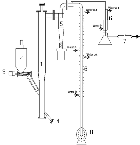
shows a schematic diagram of the fixed-bed pyrolysis reactor (0.12 m diameter × 2 m height, 1.5 kg hr−1) made of stainless steel columns. The main reactor column is 0.12 m diameter × 0.6 m height and the upper part of the bed is expanded (0.15 m diameter × 1.4 m height) to reduce the particle entrainment from the bed. An electric heater was installed at the reactor wall to heat the bed to the desired temperature and the reactor was insulated by “Kaowool.” The temperature in the bed was measured with a K-type thermocouple, and the temperature changed from 600 to 800 °C. At the beginning of the experimental run, the electric heater was turned on to heat the reactor. When the bed temperature reached the desired temperature for pyrolysis, the ASR sample was fed into the reactor through a screw feeder from the side of the reactor, and then the pyrolysis reaction began. The product gas was cooled down and sampled by passing it through a cyclone, a condenser, and a dust collector, and then its composition was determined by gas chromatography (HP 5890 II). The produced char was discharged at regular time intervals and analyzed for the heavy metal leachability by inductively coupled plasma (ICP) atomic emission spectrometer and mass spectrometer (Korean official test method on waste, 2007).
The 5000 kg/day pilot plant system
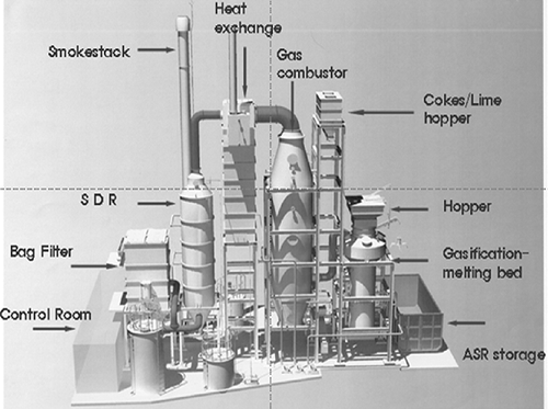
Figure 2 shows the 5000 kg/day pilot system of gasification-melting, and presents the schematic diagram of the shaft furnace of this system. As can be seen, this system consists of the shaft furnace for gasification-melting, produced gas combustor, heat exchanger, semidry reactor (SDR), bag filter, and smokestack. In the shaft furnace, ASR, limestone, and cokes were charged from the top, and then drying, gasification, and melting were performed in order, depending on the temperature and atmosphere (CitationOsada et al., 2008, 2009). After the furnace, the produced syngas was sampled and analyzed with nondispersive infrared (ND-IR) spectrometry (ZRE; Fuji, Tokyo, Japan), and then discharged through the stack after passing the combustor and the treatment system.
Gas supply system
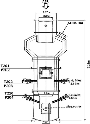
The gas supply system consisted of the air compressor and O2 and N2 gas cylinder. Air and O2 was mixed and introduced evenly to the three-flow passage installed at 1.63 m above the bottom of the furnace. N2 was used for the emergency of unexpected temperature rise, high combustible gas concentration, and high O2 concentration, and was supplied to the two-flow passage located 2.87 m above the bottom of the furnace.
Shaft furnace and combustor
The heart of this facility is the shaft furnace for gasification-melting, which has 1.60 m diaeter (exterior) and a total height of 7.25 m. As for the inner diameter, the bottom of the furnace is 0.88 m, expanding to 1.37 m in the middle and 2.62 m at the top, in order to reduce particle entrainment. The furnace walls are lined with more than 0.1 m of refractory material. The shaft-type melting furnace can be divided by four sections, drying/preheating zone, thermal decomposition zone, combustion/melting zone, and melting zone. When the ASR, cokes, and lime are fed, the feeding material is dried and preheated first and pyrolyzed in the thermal decomposition zone and char and carbon have been combusted at the high-temperature melting zone, which is formed at the bottom of the furnace (CitationOsada et al., 2009). As can be seen in , the furnace is equipped with three thermocouple probes and pressure transducers. These devices measured the temperature and pressure variation within the furnace and were connected to a computer-based data acquisition system. T210 was installed just above the melting zone, but the thermocouple could not be installed at the melting zone due to the high temperature of the melting zone. Thus, a spot thermometer (Minolta, TR-630; Tokyo, Japan) was used to measure the melting zone temperature.
After leaving the furnace, the produced gas entered a post-combustor where natural gas was injected to support combustion. The post-combustor was a horizontal cylinder, refractory lined, which could withstand temperatures greater than 1000 °C. The temperature in the combustor was measured with the three thermocouples. The main stream of gas leaving the post-combustor was then cooled with heat exchanger and treated with a post-gas treatment system, such as SDR and the bag filter.
Gas analysis and sampling equipment
The gas sampling point was located downstream of the shaft furnace. The sampling line was electrically heated (between 300 and 400 °C) to avoid condensation, and the gas temperature was kept constant to minimize line blocking until the gas reaches the cold trap of the impinger train, which was placed in a cold bath. After this first cold trap, the produced gas passed another cold trap system that was placed in a refrigerator, and the main gas constituents (CO, CO2, H2, CH4, and O2) were analyzed with an online ND-IR (ZRE, Fuji). For comparison, micro-gas chromatography (micro-GC) was used to analyze the syngas. The air pollution compounds and dioxin from the stack were analyzed by a specialized company that is officially recognized in Korea (Sanghyun E&C and DK Science by the Korean official test method; CitationKim et al., 2007). Helium was used as a tracer gas to estimate the syngas generation. A certain amount of helium was supplied with air to the furnace and then analyzed by gas chromatography (Agilent 7890A; CA, USA). With this composition of helium, the total syngas generation was calculated.
Start-up and test procedure
To begin each test run, the furnace was heated with cokes for 1 day before the experiment, and then ASR, cokes, and limestone are fed into the furnace. The computer-based data acquisition systems monitored and recorded the temperature, pressure drop, and feed rate values. When the operation of the gasification-melting system was stable, gas samples were taken for analysis. The experiments were carried out in 10 test runs and a total of 16,000 kg of ASR was gasified. Stable operation was achieved throughout the test runs. First, a test was conducted to control the operative parameters and to identify potential troubles and parts of the system to be modified and improved. One major issue was the solidification of the melting slag inside the shaft furnace when the operating conditions were not appropriate. The design of the air feeding system and the ASR, cokes, and limestone feeding system was modified several times. First of all, the size and shape of the air feeding system were changed to prevent the cooling of the melting zone and stably supply air and oxygen, where the solidification of the melting slag often occurred around the air feeding system because of water cooling inside the air feeding system. The size of feeding pipe and amount control system for cokes and limestone were adjusted for the change of feeding rate and additional systems such as vibrator were added for the smooth feeding of cokes and limestone.
Table 2 shows the major operating conditions of the ASR treatment test. As shown in , the feed rates of the cokes, limestone, air, and oxygen were changed to optimize the operating condition. The feed rate of cokes and limestone were changed with considering the test results such as the temperature change in the shaft furnace and basicity of produced melting slag. Air/fuel ratio and oxygen concentration were controlled to make the melting zone stable, where excess air feeding can cause cooling of melting slag. Other operation conditions, such as preheating condition, the slag discharge time interval, and the cokes size, were also modified and controlled carefully.
Table 2. Operating conditions of the 5000 kg/day gasification-melting system
Results and Discussion
TGA analysis
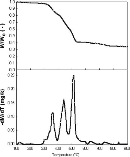
Thermogravimetric (TG) and derivative thermogravimetric (DTG) curves of ASR are shown in , where the small weight loss below 200 °C is due to the water evaporation. Then, between 310 and 550 °C, a major weight loss occurred due to the main degradation. As can be seen, pyrolysis of ASR takes place in three stages, since ASR is a mixture of many materials, such as foam, rubber, textiles, and plastics (Kim et al., 2004; CitationPartierno et al., 1998). Regarding the thermal degradation temperature of each material, in the first stage, paper, wood, and some of the textiles are pyrolyzed, with a maximum burn-off at 360 °C; in the second stage, rubber and foam are pyrolyzed, with a maximum burn-off at 440 °C; and finally, in the third stage, plastics are pyrolyzed, with a maximum burn-off at 515 °C.
Pyrolysis in Lindberg furnace
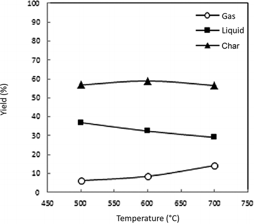
The effect of the ASR pyrolysis temperature on the product yield in a Lindberg furnace is shown in As shown in the figure, the yield of pyrolysis gas gradually increases as the reaction temperature increases, since high pyrolysis temperatures cause more degradation of the organic matter (CitationDay et al., 1996). The pyrolysis liquid yield decreases as the pyrolysis temperature increases, which arises because the higher pyrolysis temperature causes greater chain scission reactions to occur, resulting in higher yields of the lower-molecular-weight gaseous products (CitationDay et al., 1999).
The composition (H2, CO, CO2, and CH4) and calorific value of the produced gas from the light fluff pyrolysis are shown in The compositions of the product gas are H2 (10.2–17.5%), CO (11.2–19.1%), CO2 (7.3–14.5%), CH4 (20.5–23.26%), and CnHm (6.9–17.8%). As can be seen, H2 and CO increase as the pyrolysis temperature increases, due to the release of volatile matter from pyrolysis and the decrease of CnHm due to an enhancement of the pyrolysis reaction. The gross calorific value of the pyrolysis gases is calculated from the gas composition. The calorific value is in the range of 4000–6000 kcal/m3, and the value decreases with the temperature due to the decrease in the highly calorific value hydrocarbons (CnHm) such as C2H6 and C3H6. The percentage compositions of the hydrocarbon gas produced in the Lindberg pyrolysis tests are reported in . The major components are C2H4,C2H6, and C3H6. The C2H6 and C3H6 compositions decrease with an increase in the temperature, and the maximum quantity of C2H4 is obtained at 600 °C. According to CitationDay et al. (1999) and CitationNourreddine (2007), C3 hydrocarbons show noticeable decreases, whereas the yields of CO and methane continue to increase at a high temperature. However, C2H2 and iso-C4H10 increase with an increase in the temperature.
Table 3. Hydrocarbon compounds of product gas (Lindberg furnace)
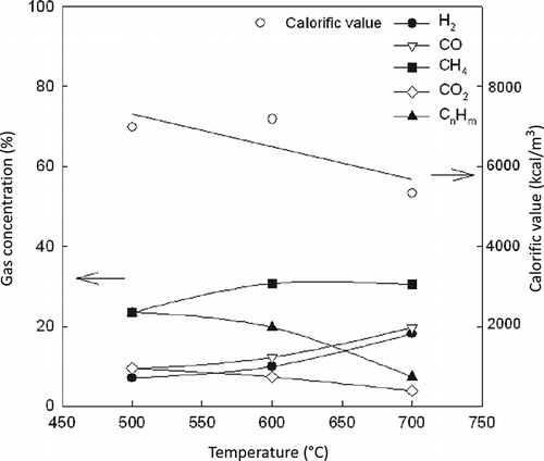
Figure 6. Effect of the pyrolysis temperature on the product gas composition and calorific value in the Lindberg furnace (light fluff).
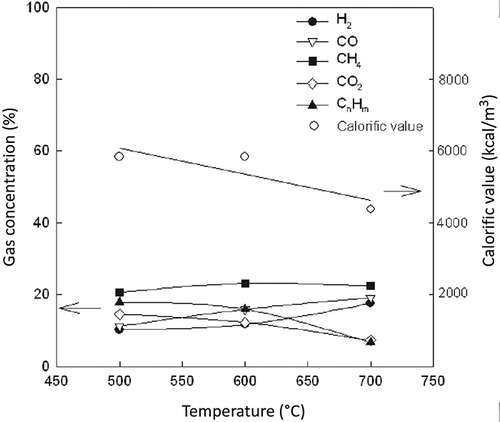
The composition (H2, CO, CO2, and CH4) and calorific value of produced gas from the heavy fluff pyrolysis are shown in The compositions of the product gas are H2 (7.1–18%), CO (9.4–19.6%), CO2 (3.9–7.3%), CH4 (23.4–30.7%), and CnHm (7.4–23.5%). As with the light fluff, H2 and CO increase and CnHm and calorific value decrease as the pyrolysis temperature increases. The calorific value is in the range of 5000–7000 kcal/m3, which is higher than that of light fluff pyrolysis gas, since heavy fluff shows higher calorific value (6123 kcal/kg) than that of light fluff (4322 kcal/kg). This is because the main components of heavy fluff are rubber and plastics, which have very high calorific values of more than 8000 kcal/kg (CitationWallman et al., 1998). The gas produced from the Lindberg pyrolysis of light and heavy fluff may be successfully employed as a type of fuel for most applications compared with the heating values of natural (8200 kcal/m3) and technical (4300 kcal/m3) gases (CitationZolezzi et al., 2004).
Fixed-bed pyrolyzer
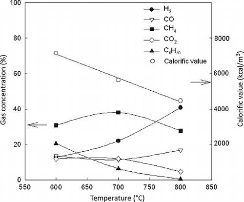
The effect of pyrolysis temperature on the gas compositions (H2, CO, CO2, and CH4) and calorific value of produced gas are shown in , where H2 and CO increase and CnHm decreases as the pyrolysis temperature increases, due to an increase in pyrolysis conversion. The compositions of the product gas are H2 (12.8–40.8%), CO (11.4–16.8%), CO2 (4.7–11.9%), CH4 (27.8–38%), and CnHm (0.5–20.5%). The hydrogen and methane compositions are high compared with other conventional continuous pyrolysis test due to the high-temperature condition for pyrolysis (CitationDay et al., 1996; CitationZolezzi et al., 2004). The gross calorific value of the pyrolysis gases, as calculated from the gas composition, decreases due to the decrease of highly calorific value hydrocarbons (CnHm). The percentage compositions of the hydrocarbon gases produced in the fixed-bed pyrolysis tests are reported in . The major components are C2H4,C2H6, and C3H6 such as the results of the Lindberg furnace. However, the amounts of all of the hydrocarbon components decrease with an increase in the temperature in the range of 600 to 800 °C during the reaction in the fixed-bed pyrolyzer. The combustible portion of the produced gas is more than 78%, reaching a maximum of 86%. The calorific value of ASR pyrolysis gas ranged between 4000 and 7200 kcal/m3, which is a high calorific value for a combustible gas (CitationGalvagno et al., 2001). shows the leachability of heavy metal in ASR and char from the pyrolysis at 600 °C. As can be seen, the results clearly indicate that although heavy metals are still present in the residual solids, the pyrolysis process does not cause any problems regarding their leachability (CitationDay et al., 1999; CitationGalvagno et al., 2001). Also, all heavy metal leaching contents satisfy the standard levels set for heavy metal leachability in Korea and in other countries, such as the United States and Canada (CitationDay et al., 1996).
Table 4. Hydrocarbon compounds of product gas (fixed-bed pyrolyzer)
Table 5. The heavy metal leachability of ASR and char
Test results at pilot plant
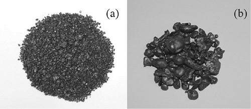
The optimum conditions for the stable operation of the ASR gasification-melting process are shown in . The amount of feeding cokes is 13.5% relative to the amount of ASR, with feeding limestone of 2.9%. The air supply and oxygen concentration are shown in . The ER (equivalence ratio: the ratio of the fuel-to-oxidizer ratio to the stoichiometric fuel-to-oxidizer ratio) is 0.23 in this condition. Slag represents approximately 17% of the initial ASR and 5.8% of the slag is metal content. Ash from the exhaust gas treatment represents approximately 3.9% of initial ASR mass. Hence, it can be calculated that the ASR volume is reduced by more than 10-fold following the thermal treatment. The generated slag and metal in the slag are shown in As shown in , 164 m3/hr of syngas was produced from the gasification-melting system.
Table 6. Operational data of the optimum conditions for the 5000 kg/day gasification-melting system
Figure 9. Slag generated from the gasification-melting system: (a) granulated slag; (b) metal grain.
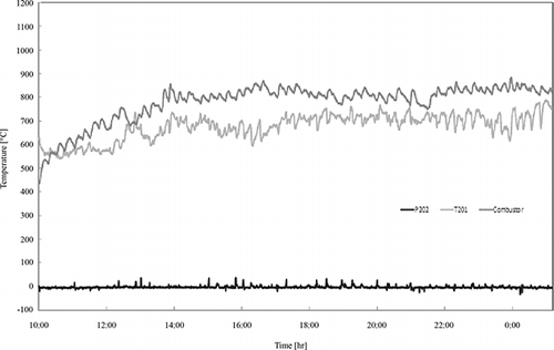
shows the temperature data of the important part of the pilot system. As shown, the temperature at the upper part (T201) of the gasification-melting shaft furnace gradually increased after the ASR was fed in. The temperature remained around 700 °C throughout the operating time, and the temperature at the outlet of the combustion chamber was 800 °C. The temperature of the melting part was about 1700 °C (1745, 1719, and 1689 °C by spot thermometer), which allowed for smooth delivery of the melt during the test period (CitationOsada et al., 2009). The pressure (P202) of the gasification-melting shaft furnace was maintained under 0, except for several high pressure peaks at the time of melt discharge.
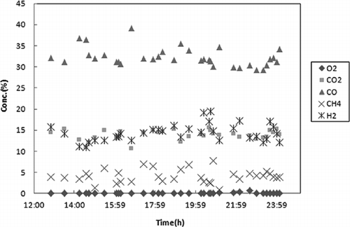
The composition of the syngas produced from the gasification-melting shaft furnace is shown in H2 ranges from 10% to 20% and CO ranges from 30% to 40%. However, CO shows higher concentration compared with the results of the laboratory-scale reactor due to the CO production from the partial oxidation of the cokes. O2 has been controlled around 0%, whereas about 15% of CO2 and 5% of CH4 have also been produced. With micro-GC analysis, the levels of H2, CO, CH4, CO2, C2H4, C2H6, and C3H8 are 14.4%, 35.4%, 2.6%, 11.98%, 1.76%, 0.25%, and 0.07%, respectively. These values are similar to the ND-IR analysis. CO is higher than any other gas compounds due to the characteristics of this shaft furnace, which uses cokes as a heat source.
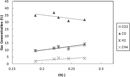
The effect of ER on the gas composition of the produced syngas is presented in When increasing the ER from 0.19 to 0.28, the concentration of the CO decreases and the H2, CO2, and CH4 concentrations slightly increase. Generally, increasing the equivalence ratio decreases the concentration of the combustible components (CO, H2, and CH4) and increases the CO2 concentration. However, as shown in , the H2 and CH4 concentrations slightly increase. On the other hand, this result may be due to the increase in the upper-zone temperature and the promotion of the decomposition of tar (CitationGarcia-Ibanez et al., 2004).
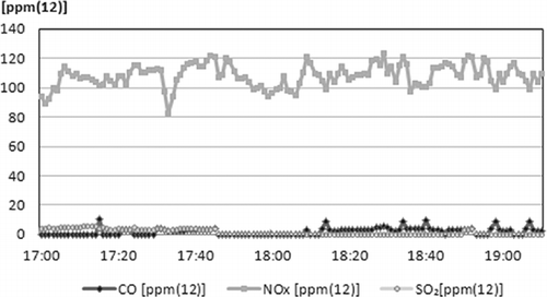
The composition of the stack air pollution compounds is shown in and . In , the CO composition is under 10 ppm, which proved that the gasification gas generated from the gasification-melting shaft furnace was completely combusted. There is also a very low amount of SO2, due to SDR. However, the amount of NOx is between 100 and 120 ppm due to the absence of a NOx treatment process such as selective catalytic reduction (SCR) or selective noncatalytic reduction (SNCR). In 2008, when the system was designed, this value would have satisfied the regulations for NOx content, but in 2010, the regulation value of NOx was reduced from 150 to 100 ppm. Therefore, another process installation for NOx will be required for operation in the future. Other components in the stack gas are shown in . Analyses were performed three times and all of the components were shown to satisfy Korean regulations for waste thermal treatment.
Table 7. Air pollution compound from stack (O2 12% reference)
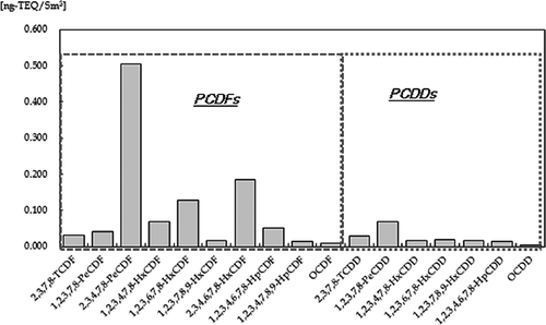
shows dioxin analysis of polychlorinated dibenzofurans (PCDFs) and polychlorinated dibenzo-p-dioxins (PCDDs) in the stack gas. The generation rate for 2,3,4,7,8-pentachlorodibenzofuran (PeCDF) was the highest for PCDD/PCDF distribution. PCDFs (1.04 ng-toxicity equivalency quantity [TEQ]/Sm3) are 6 times higher than PCDDs (0.17 ng-TEQ/Sm3), and PCDFs are produced due to the presence of PVC in the ASR (CitationJoung et al., 2007). The total TEQ is 1.21 ng-TEQ/Sm3, which meets Korean regulations (5 ng-TEQ/Sm3), showing the effectiveness of the gasification-melting system for decomposing dioxin-related compounds (CitationOsada et al., 2008).
Table 8 shows the leachability of heavy metal in the slag from pilot plant. As can be seen, all heavy metal leaching contents satisfy the standard levels set for heavy metal leachability in Korea.
Table 8. The heavy metal leachability of the slag from pilot plant
Conclusion
The TG and DTG curves of the pyrolysis of automobile shredder residue (ASR) shows three stages, as ASR contains many materials such as foam, rubber, textiles, and plastics. In the Lindberg furnace, both the amount of syngas (H2 and CO) produced and the gas yield of ASR increase as the pyrolysis temperature increases. The composition of the product gas from light fluff pyrolysis is as follows: H2 (10.2–17.5%), CO (11.2–19.1%), CO2 (7.3–14.5%), CH4 (20.5–23.26%), and CnHm (6.9–17.8%). The calorific value is in the range of 4000–6000 kcal/m3. The composition of the product gas from heavy fluff pyrolysis is as follows: H2 (7.1–18%), CO (9.4–19.6%), CO2 (3.9–7.3%), CH4 (23.4–30.7%), and CnHm (7.4–23.5%), whereas the calorific value is in the range of 5000–7000 kcal/m3, which is higher than that of light fluff pyrolysis gas due to the higher levels of components such as rubber and plastic. In the fixed-bed pyrolyzer, the amount of syngas (H2 and CO) produced increases as the pyrolysis temperature increases. The composition of the product gas is H2 (12.8–40.8%), CO (11.4–16.8%), CO2 (4.7–11.9%), CH4 (27.8–38%), and CnHm (0.5–20.5%), and the calorific value is in the range of 4000–7200 kcal/m3. The heavy metal leachability of ASR and char satisfy Korean regulations. High-temperature gasification-melting of ASR was performed 10 times in a 5000 kg/day pilot system with a shaft-type furnace. To ensure a stable operation condition, numerous instance of troubleshooting and design modification changes were performed, whereas the feed rates of the cokes, limestone, air, and oxygen were changed to optimize the operating condition. The amounts of cokes and limestone were 13.5% and 2.9% of the ASR, respectively, and the equivalence ratio is 0.23 at the optimum condition. Slag generation was 17% of the initial ASR with a metal content of 5.8% and a fly ash content of 3.9%. Syngas of H2 (10∼20%) and CO (30∼40%) was produced, as was 5% CH4. With an increase in the ER, the concentration of CO decreases and the H2, CO2, and CH4 concentrations increase slightly due to the temperature increase in the shaft furnace. With the exception of NOx, all air pollution emission levels, including dioxin, were shown to satisfy Korean regulations. All heavy metal leaching contents of slag satisfy the standard levels set for heavy metal leachability in Korea.
Acknowledgment
This work was supported by the Project on Technology Innovation of Knowledge Economy of Korea.
References
- Cho , S.J. , Jung , H.Y. , Seo , Y.C. and Kim , W.H. 2010 . Studies on gasification and melting characteristics of automobile shredder residue . Environ. Eng. Sci. , 27 : 577 – 586 . doi: 10.1089/ees.2009.0389
- Day , M. , Cooney , J.D. and Shen , Z. 1996 . Pyrolysis of auto shredder residue: An analysis of the products of a commercial screw kiln process . J. Anal. Appl. Pyrolysis , 37 : 49 – 61 . doi: 10.1016/0165-2370(96)00938-2
- Day , M. , Shen , Z. and Cooney , J.D. 1999 . Pyrolysis of auto shredder residue: Experiments with a laboratory screw kiln reactor . J. Anal. Appl. Pyrolysis , 51 : 181 – 200 . doi: 10.1016/S0165-2370(99)00016-9
- Donaj , P. , Blasiak , W. , Yang , W. and Forsgren , C. 2011 . Conversion of microwave pyrolysed ASR's char using high temperature agents . J. Hazard. Mater. , 185 : 472 – 481 . doi: 10.1016/j.jhazmat.2010.09.056
- Galvagno , S. , Fortuna , F. , Cornacchia , G. , Casu , S. , Coppola , T. and Sharma , V.K. 2001 . Pyrolysis process for treatment of automobile shredder residue: Preliminary experimental results . Energy Convers. Manage. , 42 : 573 – 586 . doi: 10.1016/S0196-8904(00)00089-3
- Garcia-Ibanez , P. , Cabanillas , A. and Sanchez , J.M. 2004 . Gasification of leached orujillo (olive oil waste) in a pilot plant circulating fluidised bed reactor. Preliminary results . Biomass Bioenergy , 27 : 183 – 194 . doi: 10.1016/j.biombioe.2003.11.007
- Horii , M. and Iida , S. 2001 . Gasification process and dry distillation of automobile shredder residue . JSAE Rev. , 22 : 63 – 68 . doi: 10.1016/S0389-4304(00)00090-4
- Joung , H.T. , Seo , Y.C. , Kim , K.H. , Hong , J.H. and Yoo , T.W. 2007 . Distribution and characteristics of pyrolysis products from automobile shredder residue using an experimental semi-batch reactor . Korean J. Chem. Eng. , 24 : 996 – 1002 . doi: 10.1007/s11814-007-0110-y
- Kim , K.H. , Joung , H.T. , Nam , H. , Seo , Y.C. , Hong , J.H. , Yoo , T.W. , Lim , B.S. and Park , J.H. 2004 . Management status of end-of-life vehicles and characteristics of automobile shredder residues in Korea . Waste Manage. , 24 : 533 – 540 . doi: 10.1016/j.wasman.2004.02.012
- Kim , S.C. , Lee , K.C. , Kim , K.H. , Kwon , M.H. and Song , G.J. 2007 . Enrichment of PCDDs/PCDFs in the cooling system of municipal solid waste incineration plants . Waste Manage. , 27 : 1593 – 1602 . doi: 10.1016/j.wasman.2006.07.007
- Kubik , K. , Donaj , P. , Swiderski , A. , Yang , W. , Blasiak , W. and Christer , F. 2008 . Assessment of ASR treatment using pyrolysis and reforming of its residences for small scale electricity generation systems . Proceedings of the Annual Meeting of Air and Waste Management Association 27th Annual International Conference on Thermal Treatment Technologies, [Place], [Dates] , 2 : 717 – 716 .
- Lin , K.S. , Chowdhury , S. and Wang , Z.P. 2010 . Catalytic gasification of automotive shredder residues with hydrogen generation . J. Power Sources , 195 : 6016 – 6023 . doi: 10.1016/j.jpowsour.2010.03.084
- Mancini , G. , Tamma , R. and Viotti , P. 2010 . Thermal process of fluff: Preliminary tests on a full-scale treatment plant . Waste Manage. , 30 : 1670 – 1682 . doi: 10.1016/j.wasman.2010.01.037
- Nourreddine , M. 2007 . Recycling of auto shredder residue . J. Hazard. Mater. , 39 : 481 – 490 . doi: 10.1016/j.jhazmat.2006.02.054
- Osada , M. , Tanigaki , N. , Takahashi , S. and Sakai , S. 2008 . Brominated flame retardants and heavy metals in automobile shredder residue (ASR) and their behavior in the melting process . J. Mater. Cycles Waste Manage. , 10 : 93 – 101 . doi: 10.1007/s10163-007-0204-y
- Osada , S. , Kuchar , D. and Matsuda , H. 2009 . Effect of chlorine on volatilization of Na, K, Pb, and Zn compounds from municipal solid waste during gasification and melting in a shaft-type furnace . J. Mater. Cycles Waste Manage. , 11 : 367 – 375 . doi: 10.1007/s10163-009-0265-1
- Partierno , O. , Cipriani , P. , Pochetti , F. and Giona , M. 1998 . Pyrolysis of automotive shredder residues: A lumped kinetic characterization . Chem. Eng. J. , 70 : 157 – 163 . doi: 10.1016/S1385-8947(98)00072-2
- Xiang , Q. , Mitra , S. , Xanthos , M. and Dey , S.K. 2002 . Evolution and kinetics of volatile organic compounds generated during low-temperature polymer degradation . J. Air Waste Manage. Assoc. , 52 : 95 – 103 . doi: 10.1080/10473289.2002.10470757
- Roy , C. and Chaala , A. 2001 . Vacuum pyrolysis of automobile shredder residues . Resour. Conserv. Recy. , 32 : 1 – 27 . doi: 10.1016/S0921-3449(00)00088-4
- Vermeulen , I. , Van Caneghem , J. , Block , C. , Baeyens , J. and Vandecasteele , C. 2011 . Automotive shredder residue (ASR): Reviewing its production from end-of-life vehicles (ELVs) and its recycling, energy or chemicals’ valorization . J. Hazard. Mater. , 190 : 8 – 27 . doi: 10.1016/j.jhazmat.2011.02.088
- Vigano , F. , Consonni , S. and Grosso , M. 2010 . Rigamonti, Material and energy recovery from Automotive Shredder Residue (ASR) via sequential gasification and combustion . Waste Manage. , 30 : 145 – 153 . doi: 10.1016/j.wasman.2009.06.009
- Wallman , P.H. , Thorsness , C.B. and Winter , J.D. 1998 . Hydrogen production from wastes . Energy , 23 : 271 – 278 . doi: 10.1016/S0360-5442(97)00089-3
- Zolezzi , M. , Nicolella , C. , Ferrara , S. , Isacobucci , C. and Rovatti , M. 2004 . Conventional and fast pyrolysis of automobile shredder residues (ASR) . Waste Manage. , 24 : 691 – 699 . doi: 10.1016/j.wasman.2003.12.005
