Abstract
This study investigates how reducing additives governed the vitrification of prepared specimens. In the experiments, pure CaO/CaCO3 and SiO2 served as the major components of glassy matrix (basicity = mass ratio of CaO/SiO2 = 2/3) with doping of hazardous metals (Cr, Cu, and Ni). The substitution ratio of CaCO3 for CaO was used as an operating parameter. The specimens were vitrified at 1400°C and a sequential extraction protocol was used to determine the phase distribution of Cr, Cu, and Ni. The volume fractions of crystalline and amorphous phases were measured using semiquantitative x-ray diffraction (XRD) analysis. A commercial software package (HSC Chemistry 6.0) was used to simulate the experiment to acquire additional information. The simulation results showed the addition of CaCO3 generated CO and CO2 at high temperature. This reducing atmosphere might enhance Cu and Ni to be easily separated from slags and elevated the levels of Cu and Ni in ingots. At higher CaCO3 mol(%), the polymerization of silicate (from sorosilicate to inosilicate) in slag rose and the CaSiO3 amount increased. In addition, the immobilization of metals and the acid resistance of slags were improved. The results indicate that CaCO3 addition is favorable for increasing the metal level in ingots and the metal encapsulation in slag in vitrification.
Vitrification techniques are often used to treat hazardous materials. The additives used in vitrification processes play an important role in vitrification. This study combines simulations (based on HSC Chemistry) and experiments to evaluate the effect of CaCO3 addition (creating a reducing atmosphere) on toxic metal stabilization in vitrification. This way, the effects of different parameters on toxic metal stabilization in vitrification can also be evaluated.
Introduction
Melting hazardous waste with silicate additives at a high temperature, namely, vitrification, is a high-energy-consumption and high-cost technology. Nevertheless, it has been used to treat hazardous materials with high toxicity, such as electroplating sludge, spent batteries, fly ash, and nuclear waste, due to its unique advantages (CitationLi et al., 2007; CitationKuo et al., 2009a; Sengupta, in press; CitationWang, 2010). Previous studies reported that the vitrification can destroy organic toxics via high temperature (>1400°C) (CitationIto, 1996; CitationKuo et al., 2003). After vitrification, molten materials can be separated into slag and ingot, due to gravity. Metals with high boiling points and densities tend to gather in the ingot, while those with low boiling points are usually concentrated in particulate matter in the flue gas. The ingot and particulate matter with high levels of valuable metals, such as Cd, Cu, Fe, Ni, and Zn, can be recovered after refinement (CitationKuo et al., 2009a). The residual hazardous metals may be encapsulated/stabilized in the molten materials (slags) that are commonly reused as a building material or an additive for cement (CitationLubeck et al., 2012; CitationZhou et al., 2010; CitationKakimoto et al., 2004). In such cases, the immobilization of hazardous metals is especially important to avoid secondary pollution.
For vitrification, the binary glass matrix system of CaO–SiO2 plays the most important role in encapsulating hazardous metals. The mass ratio of CaO to SiO2 in an original specimen, defined as basicity, is the most common parameter to control the vitrification process. Over the past few years, how basicity governs the vitrification process has been reported in a previous study (CitationKuo et al., 2008). In glassy chemistry, the most important components are Si and O, which serve as the basic elements of the slag matrix. Ca ions act as network modifiers to modify the network structure (CitationKingery et al., 1976). Next to Ca and Si, reducing atmosphere, also an important factor in the vitrification, has been reported to reduce the leachability of heavy metals and lower the melting temperature (CitationHuang and Li, 2003). In Japan, a real-scale vitrification plant using coke addition successfully vitrified fly ash into stale slag with reducing atmosphere operation (CitationKuo et al., 2003). A previous study reported that the oxygen potential governed the mineral phases in lime-fluxed iron ore sinter (CitationHsieh and Whiteman, 1989). In a vitrification process, atmosphere may also govern the formation of crystalline phases in slag. When recycling slags, the metal mobility and the crystalline characteristics of slags should be of more concern because they may affect the leachability of metals in the long term. Therefore, the effect of reducing atmosphere on vitrification is worth investigating.
Except for coke addition, an alternative approach to make a reducing atmosphere is to add CaCO3, which was preferable to CaO and was often used in steel making (CitationHsieh and Whiteman, 1993). The objective of the present study is to investigate how the substitution of CaCO3 for CaO (creating a semireducing atmosphere) in vitrification governs the mobility of metals, the crystalline characteristics and acid resistance of slag, and the composition of ingot. Software (HSC Chemistry 6.0) was used to simulate the vitrification process and to obtain further information from experimental data. Accordingly, this study also provides discussion that connects both the experimental and the simulated results. The crystalline and surface characteristics of slags and the phase distribution of metals are analyzed. The reasons for the variation of slag properties are explained in more detail with the aid of the simulations.
Experimental Methods
Sample preparation and vitrification process
To investigate the correlation between hazardous metal immobilization and the glassy matrix formed during vitrification, pure CaO/CaCO3 and SiO2 served as the agents for the formation of glassy encapsulation phases while Cr, Cu, and Ni were used as targeted hazardous metals. The targeted hazardous metal powders were added in the nitrate forms of Cr(NO3)3·9H2O, Cu(NO3)2·3H2O, and Ni(NO3)2·6H2O with a uniform concentration of 2,000 mg/kg (as metal ions) in all specimens. The transformation of nitrate into another form served as an index of mobility due to its high solubility. For the glass matrix, the mass ratio of CaO/SiO2 (the mass of CaCO3 had to be transformed into the form of CaO), adopted as a control parameter, was fixed at 2/3, which was suitable for vitrification according to a previous report (CitationLi et al., 2003). The mole percentage of [CaCO3 mol(%)] in the glassy matrix served as an operation parameter. shows the composition of the binary glass matrix in the specimens.
Table 1. Glassy matrix composition of specimens
The specimens were vitrified using an electrical melting furnace with eight MoSi2 alloy heating rods. The heating program was: room temperature to 1,000°C at 6°C/min, 1,100 to 1,400°C at 4°C/min, and held for 30 min. At molten stage during vitrification, metals with higher density crept toward the bottom of specimens, and the residual part stayed at the upper layer. After the heating program, the samples were cooled in the furnace without forced convection. The bottom of the cooled specimen formed ingot and the residual part formed slag. The labels for slags and ingots were prefixed with S and I, respectively, and suffixed with the number according to the runs of tests, listed in .
Evaluation of metals’ phase distribution using sequential extraction
The vitrified slags were weighed, pulverized, and ground to a particle size that could pass a mesh 100 sieve (smaller than 152 μm). To evaluate the mobility of metals, a sequential extraction protocol (Steps I to III) with three leaching steps that were modified from a previous study was adopted at room temperature (CitationKuo et al., 2009b). According to the extraction scheme, the metals were divided into three phases using a solution with a successively decreasing pH control in each step.
| I. | Easily mobile phase: Each sample (1 g) was mixed with 30 mL, 0.1 M, of acetic acid/sodium acetate (CH3COOH/CH3COONa, pH ∼5) and shaken for 12 hr. The samples were centrifuged with 1,500 rpm for 5 min and filtrated using a cellulose ester filter with a pore size of 0.8 μm. The residues were then extracted by the following steps and the leaching solutions were analyzed by atomic absorption spectrometry (AAS, Sens AA, GBC). This procedure was similar to that of a toxicity characteristics leaching procedure (CitationU.S. EPA, 1992). | ||||
| II. | Moderately mobile phase: The residue (0.955 g) was extracted with 30 mL, 0.1 M, of oxalic acid/ammonium oxalate (H2C2O4/(NH4)2C2O4, pH ∼4) solution for 18 hr. The extracts were centrifuged, filtered, and analyzed as in the procedure described in the easily mobile phase. | ||||
| III. | Stable phase: The residual specimen (0.1 g) was digested with mixed concentrated acids (6 mL nitric acid + 3 mL perchloric acid + 0.5 mL fluoroboric acid) in Teflon vessels by a microwave digester. The heating program for the digesting process was 25 to 180°C at 10°C/min, held isothermally for 15 min, and then cooled to room temperature. The digests were diluted to 25 mL with deionized water, filtered with a cellulose ester filter with a pore size of 0.8 μm, and analyzed by AAS (atomic absorption spectroscopy, SensAA-GBC) technique. | ||||
In this study, three representative phases, namely, the easily mobile phase, moderately mobile phase, and stable phase, were used to evaluate the metal encapsulation behavior of samples. The fractions of the three phases refer to the metals leached out from slags during the period of slag structure decomposition, possibly from no decomposition, partial decomposition, or thorough decomposition (CitationEcke et al., 2001).
Evaluation of crystalline characteristics and microstructure
The crystalline phase (CP) in slags was determined using x-ray diffraction (XRD) analysis. Slags were pulverized and ground to a fine powder with a particle size smaller than 74 μm (mesh 200). A powder diffractometer (Geigerflex 3063) with Ni-filtered CuKα radiation was used for the measurements. The detector scanned over a range of 2θ angles from 20° to 60°, at a step size of 0.01° and a dwell time of 0.15 second per step. The CPs were determined by comparing intensities and angles of peaks in the XRD pattern with those listed in the Joint Committee on Powder Diffraction Standards (JCPDS) data files.
In this study, the volume fraction of CP in slag was also measured with XRD analysis using internal standard addition (CitationCullity and Stock, 2001). The internal standard, high-purity silica crystal powder, was added with an elemental Si/sample mass ratio of 0.1; it served as a reference material in the crystalline semiquantitative analysis. The approximate volume fraction of CP was then determined according to the areas of specific peaks in comparison with that of the internal standard. The detailed procedure was given in a previous report (CitationChen et al., 2000). The amorphous volume fractions (AVF) of slags were calculated using the following equation:
The microstructures of the specimens were qualitatively examined using scanning electron microscopy (SEM)–energy-dispersive spectroscopy (Jeol JXA-840 SEM-EDS). Powdery samples with a particle size smaller than 74 μm were stuck on a metallic plate, coated with a film of Au using an ion sputter coater, and then scanned by SEM. The slags and specimens after the sequential extraction procedures I and II were all scanned to evaluate their surface structure characteristics and acid resistance.
Software simulation to predict products from vitrification
During the vitrification, some properties of products or intermediate products might not be directly measured via the involved instruments. To acquire additional information, a commercial software package (HSC Chemistry 6.0, Softhome International, Inc.) was used to simulate the whole experiment. This software contains 22 calculation modules and 12 databases. The calculation modules automatically utilize the same extensive thermochemical database, which contains enthalpy (H), entropy (S), and heat capacity (Cp) data for more than 25,000 chemical compounds. In this simulation, after setting possible products and their composition unit (kg or kmol), the composition of products was analyzed, calculated, and predicted at different temperatures using HSC Chemistry 6.0. Parts of the software simulation data provided additional information beyond the involved measurements.
Results and Discussion
Metal compositions and mass distributions of slags and ingots
shows the composition and the mass fractions of targeted metals in the produced slag and ingot. The contents of Cr, Cu, and Ni were on average 1,590, 475, and 654 mg/kg in slags, respectively, and 62,800, 233,000, and 206,000 mg/kg in ingots, respectively. The mass distribution showed that Cu (76.2%) and Ni (67.3%) mainly went into the ingot. Although the Cr level of the ingot was much higher than for slag, the result showed that most of the Cr mass (79.5%) stayed in slag. This can be explained by that the mass of slag being much higher than that of the ingot. When solid waste rich in Cu or Ni was vitrified, ingots with high levels of Cu or Ni were generated during vitrification (CitationChou et al., 2011). However, when Cr electroplating sludge was vitrified, there was no ingot generated during the vitrification process (CitationLi et al., 2007). Cr stayed in the slag and predominately existed as the form of Cr2O3. Thus, the motivation of metal coincided with the results of previous studies (CitationOden and Connor, 1994; CitationLi et al., 2007).
Table 2. Mass distribution in slag and ingot
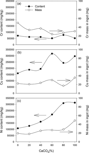
shows the contents and masses of metals in ingots. Cr levels ranged from 51,300 to 77,900 mg/kg in ingots. The variation of Cr mass was less obvious than that of Cr content. Also, the variation of Cr content and mass with CaCO3 mol(%) was less noticeable than those of Cu and Ni . The levels of Cu and Ni increased from 160,000 to 317,000 and 108,000 to 313,000 mg/kg, respectively, with the increase of CaCO3 mol(%) from 0% to 100%. Similarly, the Cu and Ni mass also increased with CaCO3 mol(%). In vitrification, these two metals with high densities and boiling points were separated from the slag phase instead of being incorporated into glassy matrix. Therefore, similar trends of separation behavior for Cu and Ni versus CaCO3 mol(%) were observed. The results showed that CaCO3 addition enhanced heavy metals being concentrated in the ingot.
Crystalline characteristics of slags
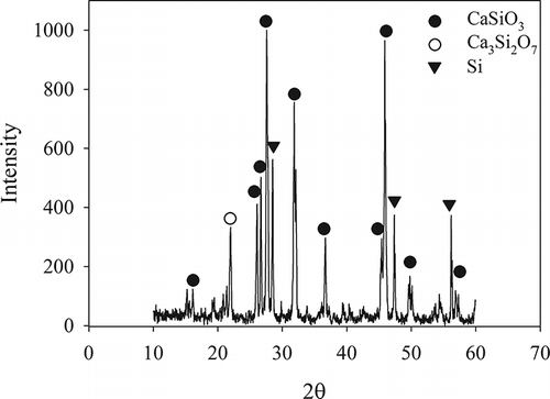
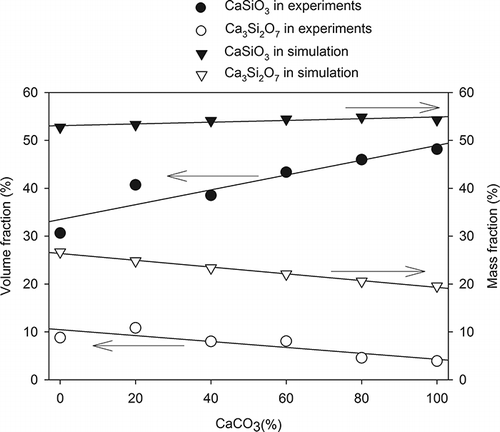
only displays the XRD pattern of the slag vitrified from R-6 specimen, because the crystalline phases (CPs) of all obtained slags were CaSiO3 (wollastonite) and Ca3Si2O7 (rankinite). shows the data from real experiments and simulation analysis for the mass and volume fractions of CPs in slags. The simulated result predicted that CaSiO3 slightly increased from 52.7% to 54.3% and Ca3Si2O7 decreased from 26.7% to 19.6%. However, the experimental result showed that CaSiO3 increased from 30.6% to 48.2% and Ca3Si2O7 decreased from 8.8% to 3.9%. The discrepancy between the two results can be explained by the following. The simulation analysis was used to predict mainly the chemical compositions of products in mass fraction (including crystallized and amorphous structure), but the input parameters in simulation did not consider how the specimens were cooled after the vitrification. The result did not show the crystalline characteristics of the products and the amounts of amorphous and crystallized products. In contrast, the semiquantitative XRD analysis measured the volume fraction of CP. The amorphous structure of products caused the major discrepancy between simulated and experimental results. In addition, the bases of simulated and experimental tests were mass and volumetric fractions, respectively, which were also responsible for the discrepancy between the two results.
Generation of reducing gases and their effect
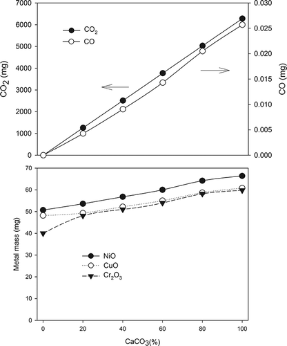
shows the simulated products during the vitrification process. At an environment with high temperature (usually >800°C), CaCO3 started to decompose into CaO and CO2 and the amount of CO2 was proportional to the CaCO3 mol(%). CO2 might react with graphite crucibles to generate CO as in the following equation:
Graphite, CO2, and CO together might create a nearly oxygen-free atmosphere, which could be regarded as a semireducing environment for vitrification. These three carbon-containing compounds served as reducing agents to react with metal ions and to change the forms of the metal compounds. According to the simulated result, metal oxides could be generated during the vitrification and their amounts increased with the increase of CaCO3 mol(%). Similar to a lime-fluxed iron ore sintering process, the specimens was heated with a reducing atmosphere and cooled in an oxidizing atmosphere. The metals were reduced to their elemental forms in the heating stage at first and then were oxidized to metal oxides in the cooling stage.
In the heating stage, the heavy metals with high densities and high boiling points, except for Cr2O3, may not be incorporated with the glassy matrix and thus will move to the bottom of melted specimens and aggregate as ingot due to their high densities (CitationLi et al., 2007). Since most of the Cr(III) entered the Si–O network of glassy matrix, it was much less available than Cu(II) and Ni(II) to be reduced in the reducing atmosphere provided from the addition of CaCO3 in vitrification. This phenomenon partially explains why the Ni and Cu levels of ingot were greatly affected by CaCO3 mol(%) in vitrification. Another possible reason is that Cu(II) and Ni(II) were easier to reduce than Cr(III) by the reducing atmosphere enhanced from the increase of CaCO3 addition during vitrification, according to the reduction reactions and corresponding standard electrode potentials of these three species as follows:
Therefore, the content and mass of Cu or Ni in the ingot increased with CaCO3 mol(%) but those of Cr did not.
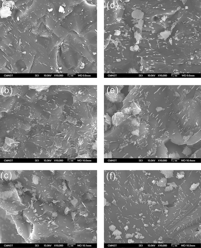
The experimental results showed that Ca3Si2O7 was converted into longer silicate chains to form CaSiO3 (Dand, 2002). With the same feature, the SEM images of slags all have sharp-edged surfaces embedded with needle-like crystals (). According to previous studies (CitationKuo et al., 2009b), the needle-like crystals coincided with the appearance of CaSiO3. In addition, the amount of needle-like crystals increased with CaCO3 mol(%), which supported the results of quantitative XRD analysis.
Phase distributions of metals
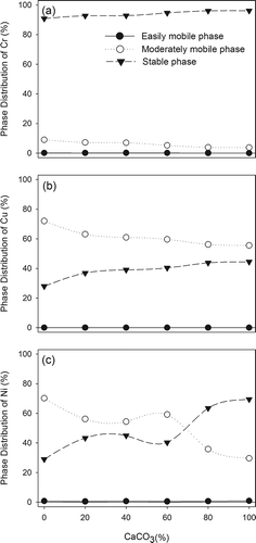
shows the phase distributions of metals in slags. Before vitrification, metal ions existed as a soluble form, and thus all of them can be regarded as easily mobile phase. For Cr, after vitrification, the values of easily mobile phase were reduced to <1% and the fractions of moderately mobile phase were between 3% and 10%. Most of Cr existed as stable phase (>90%), and the fraction of stable phase was slightly elevated with the increase of CaCO3 mol(%). In comparison with the standard for defining hazardous waste in Taiwan, the vitrified slag was pended as general industrial waste and can be recycled (CitationTEPA, 2006). The values of easily mobile phase of Cu were also smaller than 1% and the major fraction of Cu was moderately mobile phase (50–75%). The fraction of stable phase for Cu increased from 28% to 44.5% with the increase of CaCO3 mol(%) from 0% to 100%. The fractions of easily mobile phase of Ni were also <1%, similar to those of Cr and Cu. With CaCO3 mol(%) < 60%, the mass of Ni was distributed mainly in the moderately mobile phase. On the contrary, with CaCO3 mol(%) > 60%, the stable phase of Ni dominated in the three phases. In comparison with the phase distribution of these three metals, the distribution profiles of Cu and Ni were similar and slightly different from that of Cr. According to the separation phenomenon, Cr was mainly encapsulated in the slag glassy matrix, but Ni and Cu were predominately moved into the ingot. The residual fractions of metals remained in the slags and part of them might deposit on the boundary of glassy matrix. Therefore, the immobilization of Ni and Cu is not as good as that of Cr in slags.
Surface characteristics of slags after corrosion of acid
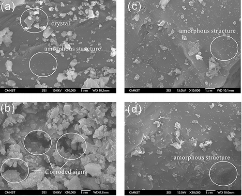
shows the SEM images of the slag surfaces from specimens R-1 and R-6 after immersion of the two acid solutions of CH3COOH/CH3COONa (pH ∼5) and H2C2O4/(NH4)2C2O4 (pH ∼3) used to determine the easily mobile phase and moderately mobile phase, respectively (see Experimental section, Evaluation of metals phase distribution using sequential extraction). For both S-1 and S-6, the needle-like crystals, CaSiO3, embedded on the surfaces of slags completely disappeared after acid leaching, indicating that these surface crystals were the first target for acid attack. Although the corrosion of needle-like crystals was similar for S-1 and S-6, the morphology of S-1 and that of S-6 were entirely different. For S-6, few crystalized deposits on the surface were observed and the structure was remained amorphous. In , there are more corroded crystals on the slag surface after the leaching of acetic solution, whereas in , a large amount of crystals covered the amorphous structure and notable corroded vestiges were observed. As discussed in the section “Phase distributions of metals,” the phase distributions of metals reveal that the metal mobility increased at high CaCO3 mol(%), due to the increase of the mass fraction of stable phase. According to the comparison of and , the different corrosion behaviors indicate that the acid resistance of slag increased with the increase of CaCO3 mol(%). The observations of SEM images supported the results of metal phase distributions.
Conclusion
This study demonstrates the role of the additives (substitution of CaCO3 for CaO) in the vitrification of prepared specimens via experiment and simulation. The simulation predicted that more CO2 and CO were generated to provide a reducing atmosphere for vitrification at high CaCO3 mol(%). The semireducing atmosphere seemed to enhance Cu and Ni being separated from the slag. Therefore, the levels of Cu and Ni in ingots were elevated. The amount of higher polymerization silicate (CaSiO3) in slags at higher CaCO3 mol(%). The results of metal phase distribution and SEM image examination of slags after acid leaching indicated that the immobilization of metals and the acid resistance of slags were improved, respectively, at high CaCO3 mol(%). The overall results showed that the CaCO3 addition is promising for vitrification processes to improve ingot metal level and slag metal encapsulation.
Acknowledgment
The authors acknowledge the financial support of the National Science Council of Taiwan under grant NSC 97-2221-E-273-004 -MY3.
References
- Brooker , R.A. and Kjarsgaard , B.A. 2011 . Silicate-carbonate liquid immiscibility and phase relations in the system SiO2-Na2O-Al2O3-CaO-CO2 at 0.1–2.5 GPa with applications to carbonatite genesis . J. Petrol , 52 : 1281 – 305 . doi: 10.1093/petrology/egq081
- Cullity , B.D. and Stock , S.R. 2001 . Elements of X-Ray Diffraction , 3rd , Upper Saddle River , NJ : Prentice Hall .
- Chen , C.Y. , Lan , G.S. and Tuan , W.H. 2000 . Preparation of mullite by the reaction sintering of kaolinite and alumina . J. Eur. Ceram. Soc , 20 : 2519 – 25 . doi: 10.1016/S0955-2219(00)00125-4
- Chou , I.C. , Wang , Y.F. , Chang , C.P. , Wang , C.T. and Kuo , Y.M. 2011 . Effect of NaOH on the vitrification process of waste Ni-Cr sludge . J. Hazard. Mater , 185 : 1522 – 27 . doi: 10.1016/j.jhazmat.2010.10.079
- Dana , J.D. 2002 . The Manual of Mineral Science , 22nd , New York, NY : John Wiley &Son . rev. by Klein, C
- Ecke , H. , Sakanakuras , H. , Matsuto , T. , Tanaka , N. and Lagerkvist , A. 2001 . Effect of electric arc vitrification of bottom ash on the mobility and fate on metals . Environ. Sci. Technol , 35 : 1531 – 1536 . doi: 10.1021/es0001759
- Hsieh L.H., and J.A. Whiteman. 1989. Effect of oxygen potential on mineral formation in lime-fluxed iron ore sinter. ISIJ Int. 29:625–34 http://dx.doi.org/10.2355/isijinternational.29.625 (http://dx.doi.org/10.2355/isijinternational.29.625)
- Hsieh , L.H. and Whiteman , J.A. 1993 . Effect of raw material composition on the mineral phases in lime-fluxed iron ore sinter . ISIJ Int , 33 : 462 – 73 . doi: 10.2355/isijinternational.45.551
- Huang , Y.C. and Li , K.C. 2003 . Effect of reducing conditions on sludge melting process . Chemosphere , 50 : 1063 – 68 . doi: 10.1016/S0045-6535(02)00622-7
- Ito , T. 1996 . Vitrification of fly ash by swirling-flow furnace . Waste Manage , 16 : 453 – 60 . doi: 10.1016/S0956-053X(96)00090-6
- Kakimoto , K. , Nakano , Y. , Yamasaki , T. , Shimizu , K. and Idemitsu , T. 2004 . Use of fine-grained shredder dust as a cement admixture after a melting, rapid-cooling and pulverizing process . Appl. Energy , 79 : 425 – 442 . doi: 10.1016/j.apenergy.2004.02.001
- Kingery , W.D. , Bowen , H.K. and Uhlmann , D.R. 1976 . Introduction to Ceramics , 2nd , New York, NY : John Wiley &Son .
- Kuo , Y.M. , Lin , T.C. , Tsai , P.J. , Lee , W.J. and Lin , H.Y. 2003 . Fate of polycyclic aromatic hydrocarbons during vitrification of incinerator ash in a coke bed furnace . Chemosphere , 51 : 313 – 19 . doi: 10.1016/S0045-6535(02)00852-4
- Kuo , Y.M. , Wang , J.W. , Chao , H.R. , Wang , C.T. and Chang-Chien , G.P. 2008 . Effect of cooling rate and basicity during vitrification of fly ash. Part 2: On the chemical stability and acid resistance of slags . J. Hazard. Mater , 152 : 554 – 62 . doi: 10.1016/j.jhazmat.2007.07.017
- Kuo , Y.M. , Chang , J.E. , Jin , C.H. , Lin , J.Y. and Chang-Chien , G.P. 2009a . Vitrification for reclaiming spent alkaline batteries . Waste Manage , 29 : 2132 – 39 . doi: 10.1016/j.wasman.2009.01
- Kuo , Y.M. , Wang , C.T. , Wang , J.W. and Huang , K.L. 2009b . Effect of Al2O3 mole fraction and cooling method during vitrification of an artificial hazardous material. Part 2: Encapsulation of metals and the resistance to acid . J. Hazard. Mater , 169 : 635 – 42 . doi: 10.1016/j.jhazmat.2009.03.151
- Kuo , Y.M. 2012 . An alternative approach to recovering valuable metals from zinc phosphating sludge . J. Hazard. Mater , 201–2 : 265 – 72 . doi: 10.1016/j.jhazmat.2011.11.081
- Li , C.T. , Lee , W.J. , Huang , K.L. , Fu , S.F. and Lai , Y.C. 2007 . Vitrification of chromium electroplating sludge . Environ. Sci. Technol , 41 : 2950 – 56 . doi: 10.1021/es062803d
- Li , C.T. , Huang , Y.J. , Huang , K.L. and Lee , W.J. 2003 . Characterization of slags and ingots from the vitrification of municipal solid waste incineration ashes . Ind. Chem. Eng. Res , 42 : 2306 – 13 . doi: 10.1016/j.jhazmat.2007.10.116
- Lubeck , A. , Gastaldini , A.L.G. , Barin , D.S. and Siqueira , H.C. 2012 . Compressive strength and electrical properties of concrete with white Portland cement and blast-furnace slag . Cem. Conc. Compos , 34 : 392 – 99 . doi: 10.1016/j.cemconcomp.2011.11.017
- Oden , L.L. and Connor , W.K. 1994 . ASME/US vitrification of residue (ash) from municipal waste combustion systems . Bureau of Mines Investigation Program Report on 1994, 24, New York: ASME Research Committee on Industrial and Municipal Wastes Subcommittee on Ash Vitrification , : 71 – 101 .
- Sengupta , P. 2012 . A review on immobilization of phosphate containing high level nuclear wastes within glass matrix—Present status and future challenges . J. Hazard. Mater , 235–36 : 17 – 28 . doi: 10.1016/j.jhazmat.2012.07.039
- Taiwan Environmental Protection Administration . 2006 . Standards for defining hazardous waste. , http://ivys.epa.gov/tw/epalaw/docfile/070020.pdf (accessed June 2009).
- U.S. Environmental Protection Administration . 1992 . Toxicity characteristic leaching procedure: SW846 method 1311. , http://www.epa.gov/osw/hazard/testmethods/sw846/pdfs/1311.pdf (accessed July 1992).
- Wang , Q. , Yan , J.H. , Chi , Y. , Li , X.D. and Lu , S.Y. 2010 . Application of thermal plasma to vitrify fly ash from municipal solid waste incinerators . Chemosphere , 78 : 626 – 630 . doi: 10.1016/j.chemosphere.2009.10.035
- Zhou , J. , Shu , Z. , Hub , X. and Wang , Y. 2010 . Direct utilization of liquid slag from phosphorus-smelting furnace to prepare cast stone as decorative building material . Constr. Build. Mater , 24 : 811 – 17 . doi: 10.1016/j.conbuildmat.2009.10.026
