Abstract
Electrospinning is a simple and versatile process to produce polymer nanofibers, which are useful for ultrafine particle filtration. In this study, a polyurethane filter with an average fiber diameter of 150–250 nm was prepared through the electrospinning process and its filtration characteristics were investigated. We found that the electrospun fiber diameter was highly dependent on the polyurethane concentration, electric field, and tip-to-collector distance. As the polyurethane concentration, electric field, and tip-to-collector distance under the same electric field increased, the fiber diameter increased. We also found that the produced filter media had a minimum collection efficiency at particles sizes from 80 to 100 nm, which implies an electrostatic attraction between the filter and the test particles. Furthermore, we observed that interception was a predominant collection mechanism at Peclet numbers higher than 10 in nanofiber filtration for ultrafine particles.
Implications:
A polyurethane nanofiber filter with excellent mechanical properties was prepared, and the effect of operating conditions on fiber morphology was examined. The filter fabricated by an electrospinning process is charged and has high filtration efficiency due to electrostatic force. Therefore, it can be a good alternative to control hazardous ultrafine particles.
Introduction
In recent years, nanotechnology has received considerable attention in various industrial fields. One example of nanotechnology is the nanofiber, which has great advantages with regard to its large specific surface area, small pore size, and high porosity, for ultrafine particle filtration, nanocatalysis, tissue engineering, protective clothing, and other biomedical applications (CitationDemir et al., 2002; CitationWang et al., 2008; CitationBhardwaj and Kundu, 2010). Among various methods developed to fabricate nanofibers, the electrospinning method is simple and effective, and it can be applied to a variety of polymers (CitationGibson et al., 2001; CitationHajra et al., 2003; CitationBarhate et al., 2006; CitationYun et al., 2007).
In the electrospinning process, an electric field is formed between a syringe needle and a grounded collector by applying high voltage to the needle of a syringe. When the electric field is greater than the surface tension of the polymer solution, a hemispheric droplet is formed at the end of the needle, followed by the formation of a Taylor cone and polymer jet spraying (CitationTaylor, 1969). The sprayed jet is divided into numerous filaments and reduced in diameter by the fast whipping motion (CitationDemir et al., 2002). During this process, fibers with nanosized diameters are formed and the fiber size is affected by several parameters, such as the composition of both the polymer and solvent, the polymer concentration, the viscosity, the electric field, and the temperature and humidity in the manufacturing environment (CitationFrenot and Chronakis, 2003).
Various polymers such as Nylon 4,6 (CitationBerrshoef and Vansco, 1999), polyethylene oxide (PEO; CitationDeitzel et al., 2001a), polyvinyl alcohol (PVA; CitationLee et al., 2004), and polyvinylidene fluoride (PVDF; CitationChoi et al., 2004) have been widely used in the fabrication of nanofibers by the electrospinning process for the past few years. However, there have been few studies about polyurethane electrospun filter media with excellent mechanical properties such as elasticity, tensile strength, durability, and water insolubility (CitationSheikh et al., 2011). Moreover, the effect of the operating parameters on fiber morphology is still questionable and studies about the collection mechanisms of electrospun filters for ultrafine particles have seldom been conducted.
For example, the effect of the electric field on electrospun fiber diameter is still uncertain. CitationBhardwaj and Kundu (2010) showed that fiber diameter became smaller with increasing electric field, due to electrostatic repulsion and rapid evaporation of solvent. However, other researchers demonstrated that a higher feed rate could be achieved with a stronger electric field, resulting in thick fiber diameter formation (CitationDemir et al., 2002; CitationZhang et al., 2005).
In filtration theory, the single fiber efficiency of a nanoparticle in a wire screen filter has been predicted with ηD = 2.7Pe−2/3, as suggested by CitationKirsch and Fuchs (1968). However, CitationWang et al. (2007) asserted that the exponent of the Peclet number to predict single fiber efficiency was somewhat higher than –2/3, that is, ηD = 0.84Pe−0.43 due to inhomogeneity of the filter. In addition, most studies have been performed with micrometer-sized filters. Therefore, the applicability of a prediction equation in nanofiber filtration is still questionable.
We prepared a nanofiber filter using a polyurethane polymer dissolved in N,N-dimethylformamide and the effects of the polymer concentration, electric field, and tip-to-collector distance on fiber morphology were examined in the present study. Furthermore, collection mechanisms of electrospun filter media for ultrafine particles were clarified through an investigation of the collection performance in nanofiber filtration.
Experimental Setup and Method
Electrospinning process
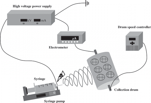
shows the experimental setup used to fabricate the polyurethane nanofibers. The polyurethane solution used in the study was prepared by dissolving a bead type of polyurethane elastomer (L194A, SK chemical) in N,N-dimethylformamide (DMF) (Sigma-Aldrich) at ratios of 5, 7, 10, 12, and 15 wt%. The prepared polyurethane solution was injected into a 5-mL volumetric syringe through a syringe pump (PHD 2000, Harvard) and supplied at a feed rate of 0.02 mL/min. To investigate the effect of tip-to-collector distance, the distance between the collection drum and a needle of 440 μm in diameter was set to 7, 8, 9, 10, and 12 cm. The rotation speed of the grounded collection drum was maintained at 90 rpm, and a stainless-steel film was attached to the surface of the collection drum. The fabricated fibers were collected on the film. The applied voltage was set to 5–20 kV using a high-voltage power supply (Korea Switching). For stable operation, the entire series of experiments was performed in a chamber, and the relative humidity was maintained below 50% for all experiments. After fiber collection, the stainless steel film was separated from the collection drum and dried in a desiccator for 24 hr so that the solvent remaining on the fiber could be completely evaporated. The electrospun filter sample was prepared by collection of the produced fibers on a circular metal mesh with a diameter of 47 mm attached to a stainless-steel film.
Solution viscosity was measured using a viscometer (DV-II+ PRO, Brookfield). The morphology of the electrospun filter was examined using a field emission scanning electron microscope (FE-SEM) (JSM-6701F, JEOL). The fiber diameter was also measured by counting more than 200 fibers observed with an FE-SEM.
Measurement of filtration performance
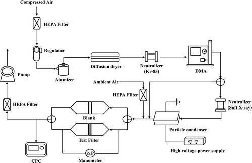
shows the experimental system used to evaluate the filtration performance of the ultrafine particles. Clean air with a flow rate of 3.2 L/min was introduced into an atomizer containing NaCl solution (0.2 wt%) and NaCl droplets were generated. The generated NaCl droplets were dried using a diffusion dryer and the test particles were adjusted using Kr-85 to create a Boltzmann charge distribution. Monodispersed and charged particles were prepared by passing the particles with charge in equilibrium though a differential mobility analyzer (DMA) (model 3081, TSI). Uncharged particles were obtained with a neutralizer (Soft X-ray, model 4530, HCT), followed by a charged particle condenser. Test particles of 0.02 to 0.3 μm in diameter were introduced into a filter test unit, and particle number concentrations were measured using a condensation particle counter upstream and downstream of the test filter. Filtration velocity was adjusted from 0.5 to 3 cm/sec in the system.
The pressure drop of the test filter was measured using a U-tube-type manometer. The mean fiber diameter, df, and the variance of the fiber diameter, σ, were calculated using Equationeqs 1 and Equation2 with the geometric mean fiber diameter, dfg, and the geometric standard deviation, σg, which were obtained using the fiber diameter distribution, measured with FE-SEM. The thickness of the filter, L, was determined using a three-dimensional (3D) profiler (VK-9710, Keyence, Inc.), and the packing density, α, was determined using Equationeq 3, where ρf was the fiber density, W was the filter weight per unit volume, and A was the filtration area.
Results and Discussion
Effect of operating parameters on fiber morphology
The morphology of nanofibers prepared by electrospinning depends on the properties of the polymer solution and the operating conditions. Many previous studies have reported on the effect of various operating parameters (i.e., polymer concentration, viscosity, and electric field) on nanofiber morphology (CitationDemir et al., 2002; CitationLee et al., 2004; CitationDeitzel et al., 2001b; CitationBuchko et al., 1999; CitationMegelski et al., 2002). Based on these previous studies, the effect of these parameters on nanofiber morphology using a polyurethane solution was examined in this study.
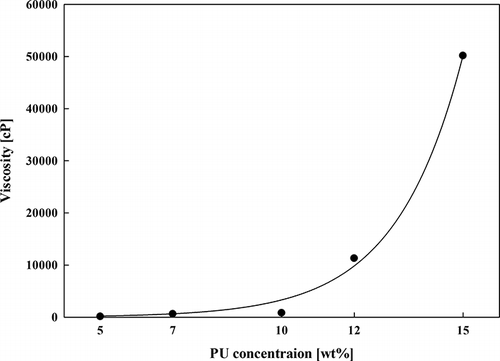
In general, the viscosity of the polymer solution increases with increasing polymer concentration (CitationBarhate and Ramakrishna, 2007). We can also see the same trend in , in which the viscosity of polyurethane solution is shown to increase to around 50,000 cP with increasing mass concentration from 5 wt% to 15 wt%, and, in particular, the viscosity increases rapidly from 10 wt%.
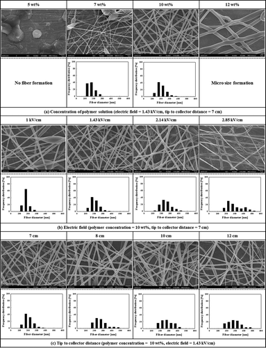
The internal morphologies of the produced electrospun filters are shown in as functions of several operating parameters. shows FE-SEM images and electrospun fiber size distributions of fibers prepared at polyurethane concentrations of 5, 7, 10, 12, and 15 wt%. However, we were not able to observe fiber formation at the solution concentration of 5 wt%, due to low viscosity. Both beads and fibers were produced at the concentration of 7 wt%; the fiber diameters were found to range from 100 to 200 nm. We were able to obtain uniform nanofibers of 150–250 nm in diameter at a concentration of 10 wt%. On the other hand, micrometer-sized fibers of 0.9–1.5 μm in diameter were formed at 12 wt%, and there was no electrospinning at 15 wt% due to the high viscosity of the solution. Therefore, a polyurethane solution of 10 wt% was selected for the investigation of the effects of other parameters. We also found the same trend as those obtained in previous studies in that fiber diameter increased with increasing polymer concentration (CitationBaumgarten, 1971; CitationDoshi and Renekier, 1995; CitationFong et al., 1999).
In addition, the effect of the electric field on fiber morphology under a fixed polymer concentration was analyzed. The electric field was set to 0.71, 1.00, 1.43, 2.14, and 2.85 kV/cm. shows FE-SEM images and fiber size distributions of fibers fabricated using various electric fields. We found that there was no electrospinning at 0.71 kV/cm because the electrostatic force could not overcome the surface tension of the polymer solution. As shown in the figure, the nanofibers prepared using an electric field of 1.43 kV/cm had uniform morphology, and their fiber diameter increased with increasing electric field. Our experimental results agreed with those of some other researchers, demonstrating thick fiber formation due to high charging ratio of the polymer solution under high electric field (CitationDemir et al., 2002; CitationZhang et al., 2005).
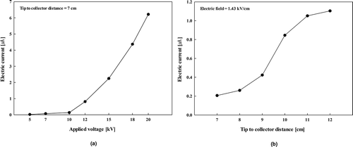
shows FE-SEM images and fiber size distributions of fibers prepared at various tip-to-collector distances under the same electric field. Tip-to-collector distances were adjusted to 7, 8, 9, 10, and 12 cm at a fixed polymer concentration of 10 wt% and an electric field of 1.43 kV/cm. We found that the fiber diameter increased with increasing tip-to-collector distance and that the distribution became broader. This may be attributed to increasing electric current. a and 5b show the electric currents at various applied voltages and tip-to-collector distances. The electric current increased with increasing applied voltage at the fixed tip-to-collector distance of 7 cm. It is conceivable that more charged polymer molecules can be produced and can migrate to the collector at higher applied voltages, resulting in thicker and broader fiber formation. CitationMunir et al. (2008) and CitationSamatham and Kim (2006) asserted that electric current can be effectively used to control the morphology of electrospun nanofibers. This result can also explain the opposite phenomenon mentioned previously, that fiber diameter decreases with increasing electric field. Strong repulsive force between polymer molecules can result in thinner fibers when a polymer solution is excessively charged.
Filtration performance
Based on the results just described, an electrospun filter was prepared using a polymer concentration of 10 wt%, an electric field of 1.43 kV/cm, and tip-to-collector distance of 7 cm. After attaching a circular mesh with the diameter of 47 mm onto the collection drum, the filter was prepared by rotation at 90 rpm for 3 hours (weight of polyurethane filter per unit area is about 1.3 mg/cm2). The physical properties of the electrospun filter are shown in . For comparison of ultrafine particles collection mechanisms, we also prepared an uncharged polypropylene filter consisting of micrometer-sized fibers. The penetrations of ultrafine particles through the test filters were measured at filtration velocities of 0.5, 1, and 3 cm/sec.
Table 1. Physical properties of test filters
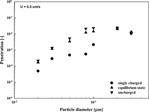
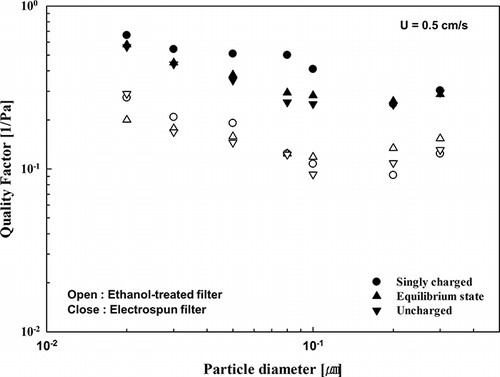
shows the penetrations of singly charged, equilibrium-state, and uncharged particles through an electrospun nanofiber filter at a filtration velocity of 0.5 cm/sec. The penetration of a singly charged particle was lower than those of particles with other charging states (charge in equilibrium and uncharged). However, there was no difference in penetration between particles in an equilibrium state and uncharged particles. A likely explanation is that most ultrafine particles in equilibrium charge consist of uncharged particles.
Generally, a filter has minimum collection efficiency at particle sizes ranging from 100 nm to 300 nm. However, the produced electrospun filter had minimum collection efficiency at particle sizes of 80–100 nm, as if electrostatic charges remain in the filter. This result indicates that the electrospun filter could be used to efficiently collect ultrafine particles without increasing the pressure drop.
Collection mechanisms of ultrafine particles in nanofiber filtration
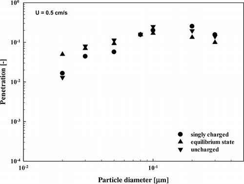
CitationLee et al. (2002) reported that the surface charges of an electret filter were removed by ethanol soaking, resulting in increasing penetration of particles. We followed the same procedure by soaking the fabricated filter media in ethanol for 1 min; we then investigated the changes in particle penetration. shows the penetrations of uncharged, equilibrium state and charged particles through an ethanol-treated filter. The particle penetration of the ethanol-treated filter was drastically increased, and the effect of particle charging states on particle penetration was less important. We were able to see that the most penetrating particle size was moved to the 100–200 nm range, which implied the neutralization of charged filter media.
The particle penetration, P is converted to the single fiber efficiency, η, given by Equationeq 4 (CitationKirsh et al., 1975). shows the experimental single fiber efficiency of an ethanol soaked electrospun filter and that of a micrometer-sized filter, plotted as a function of Peclet number:
Figure 8. Single fiber collection efficiencies of ethanol-treated filter and microsized filter as a function of Peclet number.
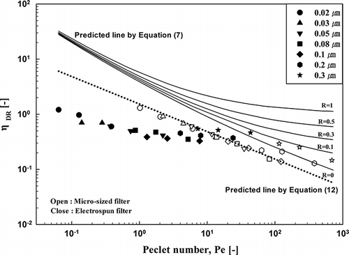
Here, ηDR is the single fiber efficiency due to diffusion and interception, ηD f is the single fiber efficiency due to diffusion, and ηR fis the single fiber efficiency due to interception; ƒ(Pe, R) is the combination term. Also, Pe is the Peclet number given by Equationeq 8, R is a dimensionless parameter of interception given by Equationeq 9, Kn is the Knudsen number, given by Equationeq 10, and k is the hydrodynamic factor for a filter with polydisperse fibers, determined by Equationeq 11:
As shown in the figure, the single fiber efficiency of a micrometer-sized filter was in better agreement with the value predicted by Equationeq 12 than that of the electrospun filter. The power of Pe was close to –1/2 for the micrometer-sized filter, and that for the electrospun filter was higher than the value calculated by Equationeq 12 and even higher than the value –0.43 predicted by CitationWang et al. (2007). The disagreement can be attributed to filter inhomogeneity in filter solidity. In addition, particle slip on a fiber surface in noncontinuum regime is another possible reason of the difference. Further study is required to elucidate this phenomenon.
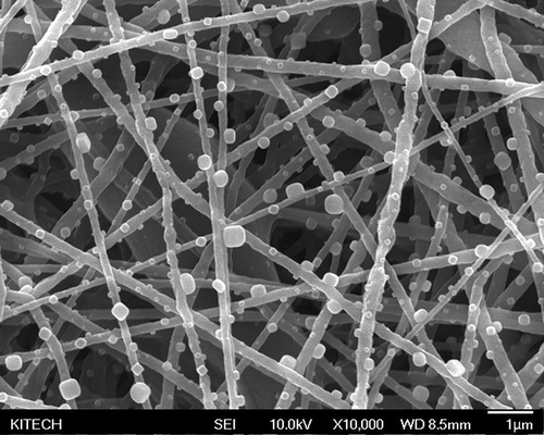
We also found that the single fiber efficiency of a micrometer-sized filter was decreased with increasing Peclet numbers. However, the experimental single fiber efficiencies of the electrospun filter increased with increasing particle size at Peclet numbers higher than 10, which resulted from the high contribution of the interception collection mechanism. These results can be identified more clearly through . The figure shows a scanning electron microscopy (SEM) image of a particle-loaded electrospun filter. As shown in the figure, the particle size was larger than the electrospun fiber diameter, which demonstrates that interception was a predominant collection mechanism in nanofiber filtration for ultrafine particles.
Filter quality factor
Filter quality factor is a useful criterion to evaluate filtration performances of various filter media. It is defined as the ratio of collection efficiency and pressure drop across the filter medium, shown in Equationeq 13,
Conclusion
Polyurethane filters with mean fiber diameters in the range of 150–250 nm were prepared by electrospinning in order to use these materials as filter media. The fiber diameter produced was proportional to the polyurethane concentration, the electric field, and the tip-to-collector distance under the same electric field. Fabricated electrospun polyurethane filter media had a minimum collection efficiency at particle size in the range of 80–100 nm, in which range the electrostatic force was exerted in the particle collection of the filter. In addition, we observed that the single fiber efficiency increased with increasing particle size at Peclet numbers higher than 10, as a result of the strong interception mechanism. This study has demonstrated that electrospinning is an effective method for fabrication of a filter medium that has electrostatic force and high filtration performance.
Funding
This research was financially supported by the Eco-innovation Project (Project number: 2012-00011-0002) through the Ministry of Environment, Republic of Korea.
References
- Barhate , R.S. , Loong , C.K. and Ramakrishna , S. 2006 . Preparation and characterization of nanofibrous filtering media. J. Membr. Sci Vol. 283 , 209 – 218 . doi: 10.1016/j.memsci.2006.06.030
- Barhate , R.S. and Ramakrishna , S. 2007 . Nanofibrous filtering media: Filtration problems and solutions from tiny materials. J. Membr. Sci , 296 : 1 – 8 . doi: 10.1016/j.memsci.2007.03.038
- Baumgarten , P.K. 1971 . Electrostatic spinning of acrylic microfibers. J. Colloid Interface Sci Vol. 36 , 71 – 79 . doi: 10.1016/0021-9797(71)90241-4
- Bergshoef , M.M. and Vansco , G.J. 1999 . “ Transparent Nanocomposites with Ultrathin Electrospun Nylon-4,6 Fiber Reinforcement. Adv. ” . In Mater Vol. 11 , 1362 – 1365 .
- Bhardwaj , N. and Kundu , S.C. 2010 . Electrospinning: A fascinating fiber fabrication technique. Biotechnol. Adv. 28: 325 – 347 . doi: 10.1016/j.biotechadv.2010.01.004
- Buchko , C.J. , Chen , L.C. , Shen , Y. and Martin , D.C. 1999 . Processing and microstructural characterization of porous biocompatible protein polymer thin films. Polymer Vol. 40 , 7397 – 7407 . doi: 10.1016/S0032-3861(98)00866-0
- Choi , S.S. , Lee , Y.D. , Joo , C.W. , Lee , S.G. , Park , J.K. and Han , K.S. 2004 . Electrospun PVDF nanofiber web as polymer electrolyte or separator. Electrochim Acta. 50: 338 – 342 .
- Davies , C.N. 1952 . “ The Separation of Airborne Dust and Particle. Proc. Inst. ” . In Mech. Eng Vol. 1B:185–199 ,
- Polymer , Deitzel, J.M., J.D. Kleinmeyer, J.K. Hirvonen, and N.C. Beck Tan. 2001a. Controlled deposition of electrospun poly(ethylene oxide) fibers, 42:816–817.
- Polymer Deitzel, J.M., J. Kleinmeyer, D. Harris, and N.C. Beck Tan. 2001b. The effect of processing variables on the morphology of electrospun nanofibers and textiles. 42:261–272.
- Demir , M.M. , Yilgor , I. , Yilgor , E. and Erman , B. 2002 . Electrospinning of polyurethane fibers. Polymer , 43 : 3303 – 3309 . doi: 10.1016/S0032-3861(02)00136-2
- Doshi , J. and Reneker , D.H. 1995 . Electrospinning process and applications of electrospun fibers. J. Electrost Vol. 35 , 151 – 160 . doi: 10.1016/0304-3886(95)00041-8
- Fong , H. , Chun , I. and Reneker , D.H. 1999 . Polymer Vol. 40 , 4585 – 4592 . Beaded nanofibers formed during electrospinning. doi: 10.1016/S0032-3861(99)00068-3
- Frenot , A. and Chronakis , I.S. 2003 . Curr. Opin. Colloid Interface Sci Vol. 8 , 64 – 75 . Polymer nanofibers assembled by electrospinning. doi: 10.1016/S1359-0294(03)00004-9
- Gibson , P. , Schreuder-Gibson , H. and Rivin , D. 2001 . Colloids Surf. A Physicochem. Eng. Asp 469 – 481 . 187– 188 Transport properties of porous membranes based on electrospun nanofibers.
- Hajra , M.G. , Metha , K. and Chase , G.G. 2003 . Sep. Purif. Technol , 30 : 79 – 88 . Effects of humidity, temperature, and nanofibers on drop coalescence in glass fiber media. doi: 10.1016/S1383-5866(02)00134-X
- Kirsh , A.A. and Fuchs , N.A. 1968 . Ann. . Occup. Hyg , 11 : 299 – 304 . Studies on Fibrous Aerosol Filters -III Diffusional Deposition of Aerosol in Fibrous Filter.
- Kirsh , A.A. , Stechkina , I.B. and Fuchs , N.A. 1975 . J. Aerosol Sci Vol. 6 , 119 – 120 . Efficiency of aerosol filters made of ultrafine polydisperse fibres. doi: 10.1016/0021-8502(75)90004-X
- Kirsch , A.A. and Stechkina , I.B. 1978 . “ The theory of aerosol filtration with fibrous filters ” . In Fundamentals of Aerosol Science , Edited by: Shaw , D.Y. New York , NY : Wiley . Ined
- Lee , J.S. , Choi , K.H. , Ghim , H.D. , Kim , S.S. , Chun , D.H. , Kim , H.Y. and Lyoo , W.S. 2004 . J. . Appl. Polym. Sci , 93 : 1638 – 1646 . Role of Molecular Weight of Atactic Poly(vinyl alcohol) (PVA) in the Structure and Properties of PVA Nanofabric Prepared by Electrospinning.
- Lee , M-.H. , Otani , Y. , Namiki , N. and Emi , H. 2002 . Prediction of collection efficiency of high-performance Electret Filters. J. Chem. . Eng. Jpn , 35 : 57 – 62 .
- Megelski , S. , Stephens , J.S. , Chase , D.B. and Rabolt , J.F. 2002 . Micro- and Nanostructured Surface Morphology on Electrospun Polymer Fibers. Macromolecules , 35 : 8456 – 8466 . doi: doi;10.1021/ma020444a
- Munir , M.M. , Iskandar , F. , Khairurrijal , K. and Okuyama , K. 2008 . A constant-current electrospinning system for production of high quality nanofibers. Rev. Sci. Instrum , 79 093904 doi: doi;10.1063/1.2981699
- Samatham , R. and Kim , K.J. 2006 . Electric current as a control variable in the electrospinning process. Polym. Eng. Sci Vol. 46 , 954 – 959 . doi: 10.1002/pen.20565
- Sheikh , F.A. , Kanjwal , M.A. , Saran , S. , Chung , W.-J. and Kim , H. 2011 . Appl. Surf. Sci , 257 : 3020 – 3026 . Polyurethane nanofibers containing copper nanoparticles as future materials. doi: 10.1016/j.apsusc.2010.10.110
- Taylor , G. 1969 . “ Electrically Driven Jets. Proc. R. Soc. ” . In Lond. A Vol. 313 , 453 – 475 .
- Wang , J. , Chen , D.R. and Pui , D.Y.H. 2007 . Modeling fo filtration efficiency of nanoparticles in standard filter media. J. . Nanopart. Res , 9 : 109 – 115 .
- Wang , J. , Kim , S.-C. and Pui , D.Y.H. 2008 . Figure of Merit of Composite Filters with Micrometer and Nanometer Fibers. Aerosol Sci. . Technol , 42 : 722 – 728 .
- Yun , K.M. , Hogan , C.J. , Matsubayashi , Y. , Kawabe , M. , Iskandar , F. and Okuyama , K. 2007 . Nanoparticle filtration by electrospun polymer fibers. Chem. Eng. Sci , 62 : 4751 – 4759 . doi: 10.1016/j.ces.2007.06.007
- Zhang , C. , Yuan , X. , Wu , L. , Han , Y. and Sheng , J. 2005 . Study on morphology of electrospun poly(vinyl alchol) mats. Eur. . Polym. J , 41 : 423 – 432 .

