Abstract
Point velocity measurements conducted by traversing a Pitot tube across the cross section of a flow conduit continue to be the standard practice for evaluating the accuracy of continuous flow-monitoring devices. Such velocity traverses were conducted in the exhaust duct of a reduced-scale analog of a stationary source, and mean flow velocity was computed using several common integration techniques. Sources of random and systematic measurement uncertainty were identified and applied in the uncertainty analysis. When applicable, the minimum requirements of the standard test methods were used to estimate measurement uncertainty due to random sources. Estimates of the systematic measurement uncertainty due to discretized measurements of the asymmetric flow field were determined by simulating point velocity traverse measurements in a flow distribution generated using computational fluid dynamics. For the evaluated flow system, estimates of relative expanded uncertainty for the mean flow velocity ranged from ±1.4% to ±9.3% and depended on the number of measurement locations and the method of integration.
Implications:
Accurate flow measurements in smokestacks are critical for quantifying the levels of greenhouse gas emissions from fossil-fuel-burning power plants, the largest emitters of carbon dioxide. A systematic uncertainty analysis is necessary to evaluate the accuracy of these measurements. This study demonstrates such an analysis and its application to identify specific measurement components and procedures needing focused attention to improve the accuracy of mean flow velocity measurements in smokestacks.
Introduction
In 2011, fossil-fuel-consuming stationary sources such as electric power plants accounted for 41% of carbon dioxide emissions in the United States (U.S. Environmental Protection Agency [EPA], 2013). This was the largest contribution by any sector of greenhouse gas (GHG) emission sources. Accurate flow measurements are critical for quantifying the levels of GHGs and other pollutants emitted from the smokestacks of power plants burning fossil fuels. The mass flow is currently measured using industrial continuous emissions monitoring systems (CEMS) installed in the smokestacks. The CEMS instrumentation determines the emission rates of regulated pollutants by multiplying the measured pollutant concentration level by the total measured flow. Large uncertainties in either measurement result in greater uncertainty in reported total emissions. Emission determinations having large uncertainty make it difficult to judge whether emission targets are being met locally—at the source, within a region, and ultimately throughout the world. To accurately assess the effectiveness of GHG mitigation strategies, GHG measurements must be traceable to reliable standards at sufficiently low uncertainties. It is standard practice to conduct multiple Pitot traverses of point velocity measurements to evaluate the accuracy of the continuous flow-monitoring devices. This study demonstrates how the exhaust duct of the Large Fire Research Laboratory (LFRL) at the National Institute of Standards and Technology (NIST) was used to assess the uncertainty of mean flow velocity measurements made by Pitot traversing techniques.
The NIST LFRL routinely conducts large-scale fire experiments and measures the flow of effluents in its exhaust duct, much like CEMS measurements at a stationary source. The exhaust duct velocity is measured with an averaging Pitot tube, Annubar. (Certain commercial entities, equipment, or materials are identified in this document in order to describe an experimental procedure or concept adequately. Such identification does not imply recommendation or endorsement by the National Institute of Standards and Technology, nor does it imply that the entities, materials, or equipment are necessarily the best available for the purpose.) The device is not capable of providing velocity distribution information, but provides an integrated average of the distribution of differential pressure induced along the device by the flow. In this work, the Annubar measurement was conducted alongside independent velocity measurements made with S-type Pitot probes, one of which was calibrated in the NIST wind tunnel. The S probes were used to conduct velocity traverse experiments and measure the velocity profile in the exhaust duct along two orthogonal chords spanning the duct diameter.
In the present comparison, a natural-gas burner under steady-state conditions was used as the emissions source. To establish a measurement baseline, velocity traverses were first conducted without the natural-gas burner (i.e., ambient flow conditions). Subsequent measurements were conducted with the burner for various inlet conditions (e.g., heat input, burner location, and flow magnitude) to simulate the range of normal operational conditions.
The velocity field was also calculated using computational fluid dynamics (CFD) and compared to the velocity profiles measured by traversing the S probes. The CFD calculations modeled only the ambient flow conditions. The following sections present a description of the experimental and numerical procedures and discussion of the results.
Experimental Methods
Facility
The NIST LFRL is a large-scale facility for the study of a broad range of fire phenomena, including the burning of materials, products, furnished rooms, and portions of buildings (CitationBryant et al., 2003). The primary measurement of the facility is the transient heat release or the amount of power generated from the burning of materials. At the time of this study, the facility was equipped with three exhaust hoods shown in , including a large hood with dimensions 9 m × 12 m, a medium hood with dimensions 6 m × 6 m, and a small hood with dimensions 3 m × 3 m. The largest hood can remove the effluent of fires at a rate of up to 2690 m3/min (95,000 ft3/min). This allows for the removal of effluents for fires with heat release of up to 10 MW. Sustained periods of burning were possible for heat release of 3 MW or less.
Figure 1. (a) Natural-gas burner under the largest of three exhaust hoods (1, large, 9 m × 12 m; 2, medium, 6 m × 6 m; 3, small, 3 m × 3 m). (b) Portion of the exhaust duct on the roof of the facility and upstream of the pollution control system.

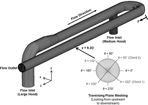
The exhaust duct, shown in Figure 1b, runs horizontally along the roof of the facility with a series of turns. The labels 1 and 2 in Figure 1b show the locations where effluents from the large hood and medium hood, respectively, enter the exhaust duct. The inner diameter, D, of the exhaust duct at the velocity traverse cross section was 1.503 m ± 0.012 m. This cross section, shown in Figure 1b, was located 9.2 D downstream of the 180° bend and 2.9 D upstream of the Annubar.
The LFRL is currently in the process of a major construction remodel and expansion. It will reopen as the National Fire Research Laboratory (NFRL), equipped with an additional hood and floor space to accommodate fires with heat release rates as large as 20 MW. With the added capacity, the new facility will be closer to the low end of heat input capacity for small gas- or oil-fired stationary combustion sources. Therefore, in addition to its contribution to fire research, it can be used as a near-industrial-scale surrogate for improving the measurement science of emissions from stationary sources.
Procedures
Two series of experiments, Series 1 and Series 2, were conducted to measure the velocity distribution in the exhaust duct. Velocity profiles were measured on two perpendicular chords of the duct cross section. In Series 1, traverses were conducted with a measurement spacing of 2.54 cm in order to fully characterize the velocity profile. The traverses were along a single chord (either chord 1 or chord 2) using a single S probe that was calibrated in the NIST wind tunnel (CitationShinder et al., 2013; CitationYeh and Hall, 2007). Point velocity measurements were conducted according to the procedures defined by EPA Method 2G (CitationEPA, 2007). The procedures account for the angle of the flow in the plane perpendicular to the traverse line—the yaw angle—and therefore determine the near-axial velocity.
Series 2 experiments were conducted by an independent stack testing company (STC), using two S probes; one on each chord. Measurement procedures followed EPA Method 2 (EPA, 2000a) with 48 total traverse points (24 per chord) or EPA Method 2G with 40 total traverse points (20 per chord). The choice of method depended on the amount of off-axis flow. Traverse points for this series corresponded to EPA Method 1 (CitationEPA, 2000b) centroid of equal area positions. A schematic of the cross section for the velocity traverse measurements is shown in . The figure shows that the two chords were nearly orthogonal with the chord 1 traverse starting at θ = 322°± 1° and the chord 2 traverse starting at θ = 50°± 1°.
Figure 2. View of the velocity traverse plane located 9.2 D downstream of 180º bend, and the Annubar located 2.9 D downstream of traverse plane.
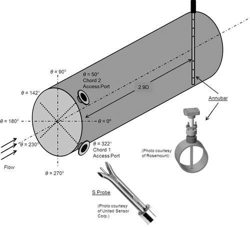
Simultaneous velocity measurements were also made using the Annubar flowmeter. The Annubar serves as the LFRL’s continuous flow-monitoring device. It was mounted in a vertical orientation and positioned 2.9 diameters downstream of the velocity traverse plane. Mean flow velocity measurements were recorded from the Annubar for each velocity traverse experiment. The Annubar was not disturbed during a series of experiments or between series. Therefore, the measurement provided a reference parameter for changes in experimental conditions.
Computational Methods
The computations performed here used the commercial solver CFD-ACE. The CFD model solves the steady, three-dimensional Navier–Stokes and continuity equations using the finite-volume method. In this method, fluxes of momentum and mass are conserved on finite volumes rather than on the differential volumes of the governing partial differential equations (i.e., Navier–Stokes and continuity equations). Consequently, on each finite volume in the computational domain, the partial differential equations are converted into a coupled set of nonlinear algebraic equations. Iterative techniques are used to solve this system of algebraic equations over the entire computational domain. Iterations are continued until the residuals (i.e., error in the numerical solutions) are reduced by six orders of magnitude. The computational domain used to model the inlet section at the large hood and the remaining exhaust ducting consisted of 822,835 finite volumes. The mesh, shown in , was composed of 605 axial grid cells with 1312 grid faces in each cross section of the flow. This resulted in 793,760 finite volumes from the inlet to the outlet of the main duct flow. The remaining finite volumes were in the section of the duct connected to the medium hood. Although the mesh included this section that connects to the medium hood, the large hood was the source for flow for all of the CFD simulations. Computations were also performed using coarser grids, with no discernible difference in velocity profiles, thereby establishing the grid independence of the solution.
The inlet flow boundary condition was set equal to the experimentally measured mass flow, while at the exit the atmospheric pressure conditions were specified. The flow computations were performed assuming the gas was both incompressible and isothermal with a constant temperature of T = 297 K. In the experiment, atmospheric pressure conditions exist at the inlet of the duct since the exhaust fans are at the far end of the duct. This is opposite of the inlet conditions defined in the CFD computation; however, the computation models the same pressure gradient along the duct as determined from the experiment. Flow profile is established by the pressure gradient for incompressible flow. Turbulence was modeled using the Kato–Launder k- model since it accounts for regions of flow stagnation. (CitationKato and Launder, 1993) The inlet turbulence intensity was taken to be 2%. As shown in , the cross section of the mesh was clustered near the wall to account for the steep velocity gradients present in the boundary layer. The fine meshing near the wall ensures the validity of the wall functions used in the turbulent model.
Results and Discussion
Velocity distribution
The flow traverses were conducted after steady-state conditions were achieved in the exhaust duct. Each velocity probe was configured with a Type K thermocouple (shielded) for gas temperature measurements and with a digital inclinometer to measure the yaw angle. The temperature inside the exhaust duct was less than 400 K (127°C) for a heat input of 2 MW. For a heated experiment, the range of temperatures along a profile generally varied within 15 K or less. The temperature was lowest near the probe access ports, due to fresh air leaking into the duct, and highest near the center of the duct. Yaw angles were the greatest near the walls, especially the wall containing the probe access port. Yaw angles at the walls were less than 15°.
Beginning with ambient flow conditions, Series 1 velocity traverses were performed for the large exhaust hood on a single chord with a uniform spacing of 2.54 cm between each traverse point. shows the near axial velocity profile across chords 1 and 2, respectively. The near axial velocity measured by the probes is calculated by
An uncertainty analysis was performed to estimate the combined uncertainty of the point velocity measurements. Assuming that the input measurements for eq 1 were mutually independent, the following equation was applied to estimate the combined uncertainty for the gas velocity:
Table 1. Uncertainty budget for Series 1 point velocity measurements
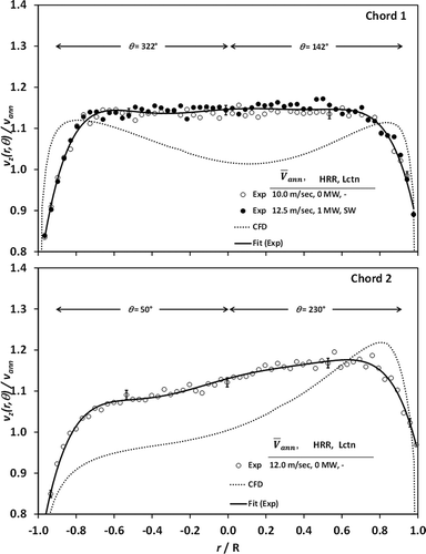
Figure 4. Measured (symbols) and simulated (dashed line) velocity distributions on chord 1 and chord 2 for ambient (open symbols) and heated (closed symbols) flow conditions, with flow starting at the large hood. The natural gas burner is located under the southwest (SW) corner of the exhaust hood. The uncertainty bars correspond to a 95% confidence interval; the nominal value is listed in .
Velocity traverses for Series 2 were conducted with two S probes: one on chord 1 and one on chord 2. In order to conduct a greater number of repeat experiments while expanding the range of experimental conditions, the point velocity measurements were conducted at centroid of equal area (CEA) locations (EPA Method 1) instead of at a uniform spacing along a chord. EPA Method 2 or Method 2G was followed depending on the amount of off-axis flow. Coarse surveys were first conducted to assess the off-axis flow. When the estimated change in average velocity due to off-axis flow was less than 0.5%, the velocity surveys were conducted following Method 2, using a total of 48 centroid of equal area positions (24 per chord, 12 per radius). Otherwise, Method 2G was followed to measure yaw angle and the near-axial velocity for a total of 40 centroid of equal area positions (20 per chord, 10 per radius).
Series 2 measurement uncertainty was based on uncertainty estimates quoted from EPA standard test methods (). In the absence of an estimate for a component measurement uncertainty in the EPA standards, uncertainty estimates from the ASTM D 3154 (CitationASTM International, 2006) standard were applied. The relative expanded uncertainty for Series 2 point velocity measurements ranged from ±0.032 to ±0.107, with a nominal value of ±0.060. When compared to Series 1, the larger uncertainty for Series 2 point velocity measurements was mostly due to the larger uncertainty in the S probe calibration coefficient, Cp, which contributes more than 85% to the combined uncertainty. The quoted uncertainty requirement for the differential pressure measurement was a percentage of the instrument full-scale measurement. At low flow velocities, this resulted in larger uncertainties for the differential pressure measurement and therefore a larger contribution to the combined uncertainty.
Table 2. Uncertainty budget for Series 2 point velocity measurements, with standard uncertainty estimates derived from EPA (Method 2 or 2G) and ASTM (D 3154) standard test methods
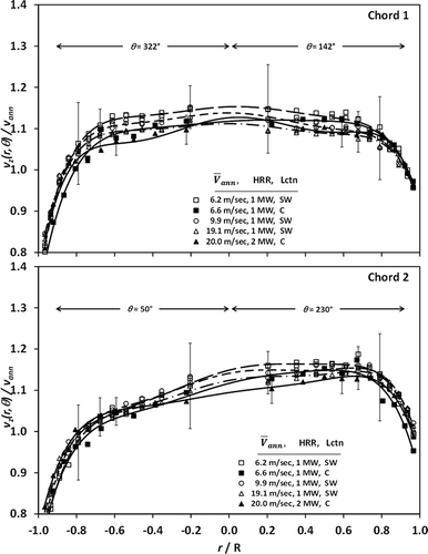
Like Series 1, Series 2 experiments began with ambient flow conditions in the large exhaust hood. Off-axis flow was not significant for the ambient flow and it was not significant for the heated flow conditions when the burner was located in the southwest quadrant of the exhaust hood. Ambient-flow velocity profiles are shown in . Each velocity measured at the probe is plotted normalized by the average velocity measured at the Annubar. The Annubar mean flow velocity is computed for the duration of the traverse. The velocity profiles are consistent with those from Series 1 for the ambient flow conditions. Least-squares polynomial fits are plotted for the repeat measurements. In the center region of the flow, the velocity ratio moves closer to unity with increasing flow magnitude. When 1 MW and 2 MW of thermal energy were added to the flow, the shapes of the velocity profiles remained consistent with the ambient flow profiles (). Moving the natural-gas burner from the southwest quadrant to the center of the exhaust duct did not have a significant effect on the velocity profiles, but the amount of off-axis flow increased. Hence, Method 2G was followed for experiments with the natural-gas burner centered under the exhaust hood.
Figure 5. Series 2 velocity profiles for ambient flow conditions in the large exhaust hood. Sample locations correspond to centroid of equal area positions. The uncertainty bars correspond to a 95% confidence interval; the range of uncertainty is stated in the associated text.
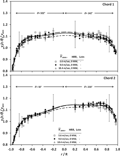
Figure 6. Series 2 velocity profiles for heated flow conditions in the large exhaust hood. Sample locations correspond to centroid of equal area positions. The natural gas burner was located under the southwest (SW) corner as well as the center (C) of the exhaust hood. The uncertainty bars correspond to a 95% confidence interval; the range of uncertainty is stated in the associated text.
CFD simulation
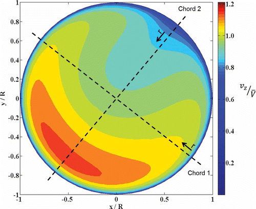
The output from the CFD model includes three-dimensional velocity vectors in each control volume of the grid. This facilitates comparison between the predicted and measured velocity profiles along chord 1 (at θ = 322°) and chord 2 (at θ = 50°). CFD results were computed for the case of the ambient flow entering the large hood. The computed velocity profiles are shown in , along with the experimental data. The CFD velocity is scaled so that the average CFD velocity equals the average measured velocity. Both the CFD results and the measured profiles exhibited similar trends. On chord 1, both the CFD and measured profiles are nearly symmetric. In contrast, the measured profile is flat at the center of the duct while the CFD profile reaches a local minimum near the center of the duct. On chord 2, both the CFD and measured profiles are skewed so that the velocity peaks on the far side just prior to the boundary layer. However, the CFD predicts a more pronounced velocity peak than the measurements. Although velocity differences were as large as 10%, the CFD is in good qualitative agreement (i.e., similar velocity profile) with the measurements. The goal of future work will be to improve the CFD predictions by using more sophisticated turbulence models.
The CFD model can also be used to visualize advanced flow features (e.g., recirculation zones, swirl decay, velocity profile development) that otherwise would require specialized experimental facilities. In the current work, the CFD predicted a recirculation zone just downstream of the 180° bend at z = 0 (see ). This flow separation induces the skewed flow distribution on chord 2. The asymmetry in the flow is better observed from the slice view of the axial velocity, shown in , at the plane of the velocity traverse, z = 9.2D downstream of the bend. The slice view demonstrates that the flow is not fully developed at the traversing plane and is skewed toward one hemisphere, which is consistent with the measurements. If not accounted for, this lack of symmetry in the flow can induce systematic error or bias in the mean flow velocity measurement, as demonstrated by Salami (1972). Consequently, the area-averaged velocity over the cross section cannot be completely determined by measuring the velocity at only two chords (i.e., chords 1 and 2). A demonstration of how the velocity distribution predicted by the CFD can be used to estimate the potential for systematic error follows.
Mean flow velocity calculation
With the knowledge of the distribution of axial velocity and gas density, , at any cross section inside a circular conduit, the actual mean flow velocity in the conduit may be determined from the following formula:
Discretization error estimate
The difference between the estimated mean flow velocity, eq 5, and the actual mean flow velocity, eq 4, is the discretization error. The CFD generated velocity slice in was demonstrated as a good qualitative estimate of the flow distribution. The total mass flow rate was defined as an inlet boundary condition for the CFD simulation and therefore can be used to define the actual mean flow velocity at the cross section. More than 59,000 data points (240 radii with 249 points/radii) were generated by interpolating the additional data using the computed grid points from the CFD slice: enough to approach an analytically determined distribution of flow velocity for the cross section. This approach is analogous to an effort by Brooks and Williams to estimate the “mapping error” of velocity traverses (CitationBrooks and Williams, 1976). They used a grid of 525 point velocity measurements from a rectangular cross section and curve fitting techniques to generate a velocity distribution for interpolating flow velocity at desired locations. The CFD-generated velocity slice is therefore a useful tool to demonstrate the impact of the number of sampling locations on discretization error.
Several studies have analyzed the effect of flow asymmetry on the accuracy of mean flow velocity techniques using point velocity measurements (CitationFrank et al., 1996; Salami, 1972) or ultrasonic transit-time measurements (CitationMoore et al., 2000). CitationSalami (1984), as well as Moore, has generated analytical distributions of flow velocity that are similar to real asymmetric flow distributions such as those measured downstream of bends, orifices, or junctions. These flow distributions have the advantage of being integrated to an exact solution, making the computation of the actual mean flow velocity possible. A similar analysis is conducted in this study by replacing the analytical distribution with the flow distribution generated from the CFD simulation—a better approximation of the actual flow.
The estimate for relative discretization error is defined by the following formula:
Estimates of mean flow velocity were computed for the CFD generated flow using eq 5 for the four integration schemes. The simulated traverse points were equally spaced along a radius when the trapezoid rule and Simpson’s rule were applied. For the EPA method, the simulated traverse points corresponded to centroid of equal area positions, in EPA Method 1. Similarly, traverse positions defined by the Gauss–Legendre method were used for this integration scheme.
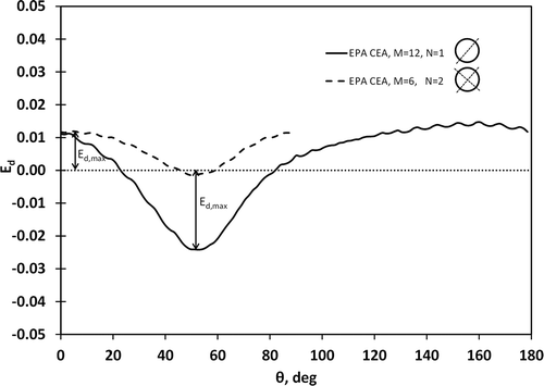
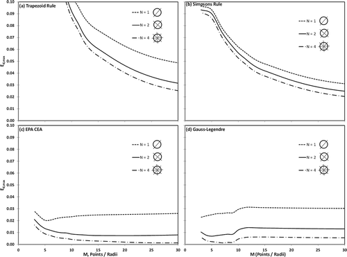
The maximum potential discretization error, Ed,max, shown in , is summarized in for the four integration schemes, for configurations of 1, 2, and 4 chords (N), and for up to 30 points per radius (M). For the asymmetric flow profile considered in this study, the EPA and Gauss–Legendre integration schemes give the lowest potential for discretization error, especially for the range of total traverse locations used in practice. Both the trapezoid rule and Simpson’s rule integration schemes would require more than 100 equally spaced points per radius on 4 radii to ensure a relative maximum-potential discretization-error less than 0.02. Using EPA or Gauss–Legendre on 2 orthogonal chords, it is possible to reduce the potential relative error to 0.01 or less. For this two chord configuration the optimum range of traverse points per radius is 8 to 15 for EPA and 3 to 9 for Gauss–Legendre.
Figure 9. Range of maximum potential discretization error with respect to number of sampling locations, number of sampling chords, and numerical integration technique.
In practice the discretization error is a bias in the measurement and therefore contributes to the systematic measurement uncertainty. The discretization error computed from the CFD simulation provides a good estimate of the measurement bias. Due to the good qualitative agreement of the simulation and the experimental results, it is reasonable to assume that the actual mean flow velocity lies within the interval . A rectangular distribution of possible values is further assumed to estimate the experimental uncertainty due to bias as
. This estimate for uncertainty due to bias is used in the next section to estimate the combined measurement uncertainty.
Mean flow velocity
For the present study, the velocity survey was performed over two diametric chords, N = 2 (2N = 4 radii), and the number of sample locations along each chord ranged from 12 to 60 (12 ≤ 2M ≤ 60). Velocity surveys were conducted on a single chord, either chord 1 or chord 2, in Series 1. The procedures improved during Series 2, with the capability to conduct the velocity surveys on both chords, simultaneously. Mean flow velocity was computed as an arithmetic average of the local velocity measurements, following the procedures of EPA Method 2 and 2G. Numerical integrations based on the trapezoid rule, Simpson’s rule, and Gauss–Legendre quadrature, were also used to compute the mean flow velocity for comparison.
Mean flow velocity resulting from the different computation methods is displayed in for Series 1 experiments. The values are normalized by the mean flow velocity measured with the Annubar. For the flow distributions considered in this study, the four mean flow velocity computations agreed to within 2.6% (2 standard deviations). On average, the EPA centroid of equal area method gave the greatest estimate of mean flow velocity, while the trapezoid rule numerical integration gave the lowest estimate. The same trend and the same level of agreement, 2.6%, were observed with the Series 2 results.
The uncertainty of the mean flow velocity is defined in this work as a combination of the measurement uncertainty and an estimate, based on simulations, of the likelihood of achieving the true mean flow velocity. Thus, the uncertainty has a contribution from the combined uncertainty of the integration of the point measurements and the estimated bias due to the discretization of the flow field as defined by the chosen measurement sampling strategy:
Figure 10. Comparison of mean flow velocity computed as an arithmetic average (EPA) and as the result of numerical integrations (trapezoid, Simpsons, and Gauss–Legendre). The uncertainty bars correspond to a 95% confidence interval; nominal values are listed in .
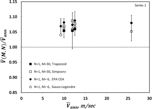
Table 3. Nominal values for the relative uncertainty, , of the estimate for mean flow velocity
Nominal estimates for uncertainty of the mean flow velocity are listed in . The estimates for the combined relative uncertainty of the integrations were on the order of 0.006 or less. Measurements in Series 1 were conducted with instrumentation that surpassed the minimum requirements for measurement uncertainty as defined by the standard test methods (EPA and ASTM) and therefore had lower uncertainty estimates than Series 2 for the integrations. The estimates for uncertainty due to bias demonstrate how increasing the number of sampling points and the number of measurement chords help to reduce the bias. For example, increasing the measurement locations from 12 on 1 chord to 48 on 2 chords reduced the uncertainty due to bias by a factor of 2 or more when applying either the EPA or Gauss–Legendre methods.
Both the S probe and Annubar infer flow velocity from a measurement of impact velocity. Without an independent method of measurement for comparison (such as a tracer dilution measurement for volume flow rate or multipath acoustic for flow velocity), it is difficult to determine which of the four mean flow computation methods will generate the most accurate results. Since the centroid of equal area methods (EPA Methods 1, 2, and 2G) is a standard test method for the stack testing industry, these methods of computing mean flow velocity are considered here. For the flow distribution considered in this study, EPA procedures had the lowest estimate of combined uncertainty when compared across physical sampling schemes and integration methods of computing mean flow velocity. The relative expanded uncertainty estimates were ±2.6% and ±1.4% for Series 1 and Series 2, respectively. A combination of lower component measurement uncertainty as demonstrated in Series 1 and an adequate number of sampling locations as demonstrated in Series 2 suggests that it is possible to reduce the expanded uncertainty to approximately ±1.0% for similar flow distributions using EPA Method 2 or Method 2G.
Figure 11. Comparison of Series 1 and Series 2 mean flow velocity measurements. The uncertainty bars correspond to a 95% confidence interval; nominal values are listed in .
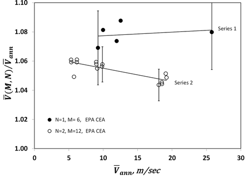
Mean flow velocity results from Series 1 and Series 2 are shown in . The values were each normalized by the mean flow velocity measured at the Annubar, which was unchanged between the series of experiments and therefore provided a reference to connect the results. The ratio is a correction factor or in situ calibration factor for the Annubar measurements. Results from Series 1 velocity traverses generated an 8% correction for the Annubar. The correction determined from Series 2 experiments ranged from 5% to 6%, and demonstrated a small dependence on the flow velocity. This lower correction is consistent with the lower S probe calibration coefficients for Series 2 experiments. It is of value to note that Series 1 and Series 2 measurements used similar experimental methodologies, but differ, as Series 2 measurements were conducted by an independent testing group, using their own equipment, instrumentation, and instrument calibrations. Also it is worthy to note that Series 1 measurements were conducted on a single chord, either chord 1 or chord 2. In general, the correction factors determined from both sets of experiments agreed to within 4% when mean flow velocity was less than 25 m/sec.
Conclusion
Determining mean flow velocity from point velocity measurements made by Pitot traversing techniques is the standard practice for evaluating the accuracy of continuous flow-monitoring devices in the smokestacks of fossil-fuel-burning stationary sources. An uncertainty analysis was conducted for mean flow velocity measurements in the exhaust duct of the NIST LFRL, which served as a surrogate stationary source. The analysis included sources of random and systematic uncertainty.
Asymmetry was identified in the duct flow that has the potential to induce systematic measurement uncertainty. The level of uncertainty will depend on the measurement strategy chosen. A CFD simulation of the flow distribution was in good qualitative agreement with the experimental results and therefore was used to estimate the systematic uncertainty induced by the flow asymmetry and choice of mean flow velocity integration scheme. The analysis, using the simulated flow distribution, showed that the centroid of equal area and Gauss–Legendre integrations schemes resulted in the lowest contribution to the systematic measurement uncertainty for the flow asymmetry considered. Using either of these schemes with point velocity measurements on two orthogonal chords, the maximum potential for discretization error can be reduced to 1.0% or less. The results of this study demonstrate how CFD simulations of real flows can be used to estimate as well as reduce the discretization error of mean flow velocity measurement techniques.
Two series of mean flow velocity measurements were conducted in the LFRL exhaust duct by two independent groups. The groups achieved agreement to within 4.0%, using similar experimental procedures, but independent instrumentation and instrument calibrations. The difference in the S probe calibration coefficients is a potential cause for the discrepancy between the results. When considering the centroid of equal area integration scheme (EPA Methods 1, 2, and 2G), the uncertainty analysis for both series of measurements resulted in estimates of ±2.6% and ±1.4% for the expanded uncertainty of the mean flow velocity measurements. It is possible to reduce the expanded uncertainty to ±1.0% or less for a similar flow distribution by using an adequate number of point velocity measurements and improved S probe calibrations.
Acknowledgment
The authors gratefully acknowledge the technical and engineering support provided by Marco Fernandez, Laurean DeLauter, Doris Rinehart, and Anthony Chakalis and data acquisition support provided by Artur Chernovsky. They are grateful for calibration services provided by Iosif Shinder and the Fluid Metrology Group, and for technical guidance provided by Anthony Hamins, Jiann Yang, and Michael Moldover. Research support by the NIST Office of Special Programs—Greenhouse Gas and Climate Science Measurements, James Whetstone Program Manager—is gratefully acknowledged.
Additional information
Notes on contributors
Rodney Bryant
Rodney Bryant, Elizabeth Moore, Matthew Bundy, and Aaron Johnson are research scientists and engineers at the National Institute of Standards and Technology, in Gaithersburg, MD.
Olatunde Sanni
Olatunde Sanni was a student engineer in training at the National Institute of Standards and Technology during the execution of this study. He is currently an applications engineer with National Instruments in Austin, TX.
References
- ASTM International. 2006. Standard Test Method for Average Velocity in a Duct (Pitot Tube Method). D3154-00. West Conshohocken, PA: ASTM International.
- Brooks, E.F., and R.L. Williams. 1976. Flow and Gas Sampling Manual. EPA-600/2-76-203, Washington, DC: U.S. Environmental Protection Agency.
- Bryant, R.A., T.J. Ohlemiller, E.L. Johnsson, A. Hamins, B.S. Grove, W.F. Guthrie, A. Maranghides, and G.W. Mulholland. 2003. The NIST 3 Megawatt Quantitative Heat Release Rate Facility. NIST Special Publication 1007. Gaithersburg, MD: National Institute of Standards and Technology.
- Dahlquist, G., and A. Bjorck. 1974. Numerical Methods. Englewood Cliffs, NJ: Prentice Hall.
- Frank, S., C. Heilmann, and H.E. Siekmann. 1996. Point-velocity methods for flow-rate measurements in asymmetric pipe flow. Flow Measurement and Instrumentation 7(3–4): 201–9. doi:10.1016/S0955-5986(96)00015-5
- Jain, M.K., S.R.K. Iyengar, and R.K. Jain. 1985. Numerical Methods for Scientific and Engineering Computation. New York, NY: Halsted Press.
- Kato, M., and B.E. Launder. 1993. The modelling of turbulent flow around stationary and vibrating square cylinders. Paper presented at Ninth Symposium on Turbulent Shear Flows, Kyoto, Japan, August.
- Moore, P.I., G.J. Brown, and B.P. Stimpson. 2000. Ultrasonic transit-time flowmeters modelled with theoretical velocity profiles: Methodology. Measurement Science & Technology 11(12): 1802–11. doi:10.1088/0957-0233/11/12/321
- Salami, L.A. 1971. Errors in the velocity-area method of measuring asymmetric flows in circular pipes. Paper presented at International Conference on Modern Developments in Flow Measurements, Harwell, England, September.
- Salami, L.A. 1984. Application of a computer to asymmetric flow measurement in circular pipes. Transactions of the Institute of Measurement and Control 6(4): 197–206. doi:10.1177/014233128400600403
- Shinder, I.I., J.C. Crowley, B.J. Filla, and R.M. Moldover. 2013. Improvements to NIST’s Air Speed Calibration Service. Paper presented at FLOMEKO, Paris, France, September.
- U.S. Environmental Protection Agency. 2000a. Determination of Stack Gas Velocity and Volumetric Flow Rate (Type S Pitot Tube). EPA Method 2. Washington, DC: U.S. Environmental Protection Agency.
- U.S. Environmental Protection Agency. 2000b. Sample and Velocity Traverses for Stationary Sources. EPA Method 1. Washington, DC: U.S. Environmental Protection Agency.
- U.S. Environmental Protection Agency. 2007. Determination of Stack Gas Velocity and Volumetric Flow Rate with Two-Dimensional Probes. EPA Method 2G. Washington, DC: U.S. Environmental Protection Agency.
- U.S. Environmental Protection Agency. 2013. Inventory of U.S. Greenhouse Gas Emissions and Sinks: 1990–2011. EPA 430-R-13-001. Washington, DC: U.S. Environmental Protection Agency.
- Yeh, T.T., and J.M. Hall. 2007. Airspeed Calibration Service. NIST SP 250-79. Gaithersburg, MD: National Institute of Standards and Technology.

