
Abstract
In the disposal of electronic waste, cathode ray tube (CRT) funnel glass is an environmental problem of old television sets. Removal of the lead from CRT funnel glass can prevent its release into the environment and allow its reuse. In this research, we reference the dry progress productive technology of sodium silicate, the waste CRT glass was dealt with sodium silicate frit melted and sodium silicate frit dissolved. Adding a certain amount of Na2CO3 to the waste CRT glass bases on the material composition and content of it, then the specific modulus of sodium silicate frit is obtained by melting progress. The silicon, potassium and sodium compounds of the sodium silicate frit are dissolved under the conditions of high temperature and pressure by using water as solvent, which shows the tendency that different temperature, pressure, liquid-solid ratio and dissolving time have effect on the result of dissolving. At 175°C(0.75MPa), liquid-solid ratio is 1.5:1, the dissolving time is 1h, the dissolution rate of sodium silicate frit is 44.725%. By using sodium sulfide to separate hydrolysis solution and to collect lead compounds in the solution, the recovery rate of lead in dissolving reached 100% and we can get clean sodium silicate and high purity of lead compounds. The method presented in this research can recycle not only the lead but also the sodium, potassium and other inorganic minerals in CRT glass and can obtain the comprehensive utilization of leaded glass.
Implications:
Waste cathode ray tube (CRT) funnel glass has become a serious environmental problem throughout the world. However, some techniques in the processing of CRT waste have disadvantages such as low lead recovery, low level of comprehensive utilization, technical constraint, economic costs, and other factors, so the actual practical application is still not possible. Therefore, in order to solve lead pollution existing in the waste CRT glass and to solve resource utilization problems, it is necessary to develop a waste CRT process technology that is friendly to environment, cost-saving, and feasible.
Introduction
With the development of technology, the progress of society, and the accelerating of the update of electronic display technology, the cathode ray tube (CRT) has gradually been replaced by the liquid crystal display (Poon, Citation2008). A large amount of CRT TVs (including the use of CRT monitors for desktop computers) fell into disuse, resulting in the CRT glass being discarded as wastes. Waste CRT glass contains heavy metals such as lead. If not disposed properly, it will cause great harm to the environment and cause waste of resources. Waste CRT glass has caused a serious environmental problem throughout the world, especially in China. With considerable amount of e-waste being generated, developing nations will have to deal with more old computers and TVs than developed countries by 2018 or earlier, because of the lax supervision and environmental regulations concerning e-waste in the developing world (Yu et al., Citation2010).
At the beginning of the research on the waste CRT leaded glass, it is converted to some other products, such as foam glass (Méar et al., Citation2006a, Citation2006b; Bernardo and Albertini, Citation2006), sintered brick (Industry Council for Electronic Equipment Recycling [ICEER], Citation2004), crystalline silicon (Chen et al., Citation2010), glass ceramics (Andreola et al., Citation2005, Citation2007; Bernardo et al., Citation2007a, Citation2007b), fine aggregate in cement mortar (Ling and Poon, Citation2011), and other products (Nnorom et al., Citation2011; Andreola et al., Citation2008). Although these methods provide solutions for lead pollution of the waste CRT glass very well, there also are potential risks to human health and environment. Therefore, the most effective way is to extract lead from the waste CRT glass. U.S. Corning reported an acid leaching method for waste CRT glass (Goforth et al., Citation1994). On this basis, some researchers recycled lead using subcritical hydrothermal treatment of acid leaching method (Miyoshi et al., Citation2004) and acid leaching deposition method (Pruksathorn and Damronglerd, Citation2005). In order to enhance the efficiency of acid leaching, ultrasonic (Saterlay et al., Citation2001), subcritical water (Miyoshi et al., Citation2004), and mechanical activation (Yuan et al., Citation2012) methods have already been reported. The above methods focused on reducing the lead content in waste CRT glass through acid leaching method, but other metals such as Ba and Mg are leached simultaneously. Other technologies are also developed, such as mechanochemical process (Birke et al., Citation2004; Sasai et al., Citation2008; Guo et al., Citation2010; Yuan et al., Citation2013a, Citation2013b), the self-propagating process (Chen et al., Citation2009), the reduction process by reaction with silicon carbide and titanium nitride (Yot and Méar, Citation2009), the chloride volatilization (Grause et al., Citation2014), etc. However, these techniques in the process have some disadvantages, such as low lead recovery, low level of comprehensive utilization, technical constraint, and economic costs.
In this paper, a new method was developed to recover lead while producing sodium silicate from waste CRT glass in dry process, thus we obtained the trend that some typical factors about sodium silicate frit melting and dissolving had impact on the production effectiveness. In addition, we got lead-free sodium silicate, optimal dosing ratio of sodium sulfide precipitation agent in the experiment, and lead sediment as compounds returning to source of lead smelting and then realized the recycle of lead resource.
Materials and Methods
Materials and pretreatment method
The funnel glass and screen glass were separated from color television CRTs (produced in 1989, Hitachi, 14 inches). Funnel glass were broken and milled by granite lining crushing device (SM-35; Xianlin Machinery, Zhangqiu, China). Then it was sifted through 100-mesh sieve to prepare as sample.
In the optimal parameter status determined in the melted experiment, it can be product moduli 2.0, 2.5, and 3.0, three kinds of sodium silicate frit, respectively. Then, sodium silicate frit was milled and sifted through 100-mesh sieve as sample.
Sodium silicate frit melting
The softening temperature and chemical stability of waste lead CRT glass decrease with the increase of lead oxide. The melting point of lead glass ranges from 370 to 540 °C and is far below the standard melting temperature (1400 °C) of the sodium silicate dry process production system.
Based on the silicon, potassium, and sodium contents of the CRT glass, we added proper amount of sodium carbonate and let the mixed materials and the specified modulus sodium silicate frit have almost the same composition (regardless of the lead and other impurities). The sample would be put in the cylindrical oxidation platinum crucible, into the box type resistance furnace (XS-6-13; Jingwei Electric Furnace, Yixing, China). The temperature was raised intermittently from 0 °C to determined temperature by steps, every 200 °C per step and was kept at this temperature for 30 min. The maximum temperature melting experiments were set at 700, 800, 900, 1000, 1100, and 1300 °C, respectively. The heating power was 2800 W. The sample has the following reaction under high temperature conditions:
In eq 2, is the rate of melted reaction (%),
is the loss on ignition (g), is molar mass of CO2,
is the quality of adding Na2CO3 (g), and
is molar mass of Na2CO3.
The dissolution of sodium silicate frit
The dissolution process was carried out at high temperature using a magnetic drive autoclave (GS1L; Zhengwei Machinery, Shanghai, China). We analyzed the relationship between the parameters (such as sodium silicate frit modulus, liquid-solid ratio, melting temperature, time of heat retaining) and the effect of dissolving sodium silicate prepared from the waste CRT glass. The silicate moduli were 1.5, 2.0, 2.5, and 3.0; liquid-solid ratio was set to 1.5:1, 2:1, 2.5:1, 3:1, 3.5:1, and 4:1; dissolving temperature (system self pressure) was set to 150 °C (0.2 MPa), 175 °C (0.75 MPa), 200 °C (1.5 MPa), 225 °C (3 MPa), and 250 °C (4 MPa); and dissolving time was set to 1, 2, 3, 4, and 5 hr, respectively, in this experiment. The rate of sodium silicate frit dissolution was an important index of process parameters, calculated as follows:
Specific operation was as follows. Samples in sodium silicate frit were added deionized water according to the set of liquid-solid ratio and were mixed in the magnetic drive autoclave in high-temperature and -pressure reaction. The rotor speed and the reactor heating voltage were set to 400 rpm and 125 V, the heat of kettle fell was preserved at the setting time after heating reached the specified temperature. After the period of heat preservation, the speed of rotor and voltage were adjusted to 0 rpm and 0 V, the mixed samples were removed after the kettle fell to natural atmospheric pressure, the supernatant and lower precipitation were separated after standing 30 min, the precipitation was washed dried and weighed, and the dissolution rate was calculated by eq 3. The supernatant was leaded sodium silicate solution, and substratum the precipitate.
Separation and recovery of lead of sodium silicate solution
Sodium sulfide was added to the sodium silicate solution with 20 times dilution to study how the quantity of sodium sulfide affects the rate of lead removal in sodium silicate solution.
The Pb:M was selected as 1:1, 1:1.5, 1:2, 1:2.5, and 1:3, respectively, according to the molar ratio between the lead concentration in the sodium silicate solution and sodium sulfide. The quantitative sodium sulfide was added to the sodium silicate solution, and the sediment was subjected to qualitative analysis. Moreover, removal rate of lead in sodium silicate solution was calculated according to the concentration of lead in the original and the treated sodium silicate solutions, as follows:
Analytical method
Analysis of leaded glass and insoluble solid composition
The waste CRT glass and insoluble solid composition were determined by automatic X-ray fluorescence (XRF) spectrometry (EDX3000; Shimadzu, Tokyo, Japan) and inductively coupled plasma atomic emission spectroscopy (ICP-AES; Vista MPX; Varian, CA, USA). XRF analytical accuracy was 0.05%; the scope of analysis was 5B to 92U; pipe voltage was 5–50 keV. and detection limit of heavy elements was at ppm level.
Determination of lead concentration in sodium silicate solution before and after the lead separation and recover
Because of the presence of silicon can affect the analysis accuracy of the ICP atomic fluorescence spectrometer for lead content, the sodium silicate solution was diluted and digested, as in the following steps: 1 mol·L−1 dilute nitric acid was added to 10 mL prepared sodium silicate sample to conduct digestion experiment. Due to the hydrolysis of sodium silicate solution, the solution was alkaline; then an excess of dilute nitric acid was added and the solution was acidic, which generated milky silicic acid precipitate. The reaction equation is as follows:
Component determination and observation of the micromorphological characteristics of lead precipitate in the separation of sodium silicate solution
The structure of the precipitate of lead in sodium silicate was observed by scanning electron microscope (S-4800; Hitachi, Tokyo, Japan). At the same time, its components were analyzed by energy dispersive X-ray spectrometry (Noran 7; Thermo Fisher Scientific, MA, USA). Among them, the secondary electron resolutions were 1.0 nm (15 kV) and 2.0 nm (1 kV); backscattered electron resolution was 3.0 nm (15 kV); electron gun was cold field emission electron source; accelerating voltage was 0.5–30 kV (0.1 kV/step, variable); and magnification was 30–800,000.
Results and Discussion
Component analysis of waste CRT glass
Chemical composition of the waste CRT glass was determined by X-ray fluorescence spectrometry and inductively coupled plasma atomic emission spectroscopy. The PbO content is 22.03%. The content of each component is shown in .
Table 1. Chemical composition of the CRT funnel glass
Conditions of sodium silicate frit melting
Comparing the physical state of frits in melting experiments, the maximum melting temperature was 700, 800, 900, 1000, 1100, and 1300 °C, respectively, and the melting reaction rate was calculated by experiment ignition loss (eq 2). Under the 700, 800, 900, 1000, and 1100 °C melting temperatures, the results are shown in .
Figure 1. Sodium silicate frit firing effect at temperatures of 700–1100 °C (temperature from low to high from left to right).
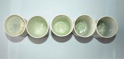
As can be seen from , at 700 °C, the melting results retained carbon dioxide foaming expansion conditions in sodium silicate forming process. At 800 °C, there was still some remaining foam inside, a small amount of foam was adhered in the crucible wall, and frit was emulsified. The phenomenon of melting process at 900 and 800 °C exhibited similar patterns, but no foam was observed in the crucible wall, which means that the frit emulsion had improved. Limpid frits were obtained at 1000 and 1100 °C.
There was a positive correlation between the melting temperature and reaction rate of melting system, as shown in .
Figure 2. Relationships between melting temperature and ignition loss and reaction rate of melting system.
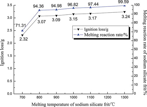
From the , we can see that as the temperature of the melting increased from 700 to 800 °C, the reaction rate of melting rapidly increased from 71.13% to 94.36%. Increments were reduced as follows: the increments in 900, 1000, 1100, and 1300 °C were increased 0.62%, 1.84%, 0.62%, and 2.15%, respectively. At 700 °C, the expansion of the carbon dioxide foam showed that the melting reaction was slowly. Since the melting points of the leaded glass and soda were 851 and 370–540 °C, respectively, the lowest melting point of the mixed materials was also about 800 °C, so the melting efficiency improved at 800 °C significantly. The melting temperature continued to improve; the reaction of mixed materials frit was accelerated. After it was cooled, the fixed modulus of sodium silicate frit was determined. Considering the actual costs of production of energy and operation of the manufacturing reactors, we chose 1000 °C as the temperature of melting process in the next dissolution experiments.
Conditions of dissolution of sodium silicate frit
Four factors were evaluated for the impact on the dissolution rate of sodium silicate frit. The four factors were modulus of the sodium silicate, liquid-solid ratio, temperature (self-built pressure of system), and dissolution time.
The experimental results are shown in .
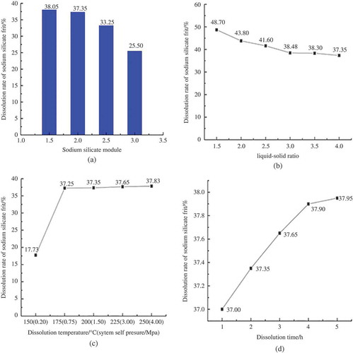
Figure 3. The regular patterns of dissolving sodium silicate frit under the various conditions.
The influence of sodium silicate modulus on the dissolution rate of sodium silicate frit
Alkaline substances combined with high temperature in the melting process promote the breakage of glass network structure, which causes the dispersion of lead oxide inside vitreous body structure. Based on the actual production process of sodium silicate, sodium carbonate as alkaline substance (pure analytically) was added in the experiment.
Modulus of sodium silicate is the molar ratio between the silica and alkali metal oxide in sodium silicate. The molecular formula of sodium silicate is X2O·nSiO2, X is alkali metal, and n is modulus. Silicate modulus determines the percentage ratio of alkali metal oxide and silica. As shown in , the dissolution rate of sodium silicate frit decreased obviously as the modulus increased. The moduli of sodium silicate frit were 1.5, 2.0, 2.5, and 3.0, and the rates of dissolution were 38.05%, 37.35%, 33.25%, and 25.50%, respectively.
When sodium silicate frit dissolves, the following reaction occurs:
When modulus of sodium silicate was lower, the sodium silicate frit had higher amount of alkali relatively, and content of sodium ion in the liquid increased the dissolution of sodium silicate frit. The dissolution rate and efficiency of sodium silicate frit were proportional to alkali content, and they were inversely proportional to the amount of silicon, namely, low modulus was soluble, high modulus was insoluble. When sodium silicate modulus was 3.0, the residue appeared as a small amount of glassy insoluble substance, dissolution was ineffective. When modulus was less than 2.0, the dissolution rate of the sodium silicate frit could be further improved; when modulus was 1.5, the dissolution rate of the sodium silicate frit was 38.05%, which was similar to 37.35% (the rate in modulus 2.0) and increased with tiny increment. Considering that there is no application in industry production when sodium silicate is less than 2.0, we performed the next dissolution experiments with the modulus of sodium silicate frit at 2.0.
The influence of liquid-solid ratio on the dissolution rate of sodium silicate frit
Liquid-solid ratio mainly determines the concentration of sodium ion when the sodium silicate frit dissolves in the liquid. As shown in , the dissolution rate of sodium silicate frit decreased significantly as liquid-solid ratio increased and was stabilized finally. The dissolution rates were 48.70%, 43.80%, 41.60%, 38.48%, 41.60%, and 37.35% when the liquid-solid ratios were 1.5:1, 2:1, 2.5:1, 3:1, and 3.5:1, respectively. Improvement of liquid-solid ratio reduced the concentration of sodium ions in the solution, so the dissolving became difficult gradually. We only collected a relatively small amount of liquid after the dissolved reaction in low liquid-solid ratio (e.g., 1.25:1, 1.375); lower liquid-solid ratio would cause more difficulty to the treatment after frit dissolved. To guarantee the experimental results, liquid-solid ratio of 1.5:1 was selected for the next experiment.
The influence of temperature (self-pressure of system) on the dissolution rate of sodium silicate frit
Dissolving temperature and pressure mainly affect the activation energy of reactant in hydrolysis process. As shown in , dissolution rate of sodium silicate frit increased with the increase of the dissolution temperature (system self-pressure) and stabilized eventually; dissolving conditions of 150 °C (0.2 MPa), 175 °C (0.75 MPa), 200 °C (1.5 MPa), 225 °C (3.0 MPa), and 250 °C (4.0 MPa) corresponded to the dissolution rates of 17.73%, 37.25%, 37.35%, 37.65%, and 37.83%, respectively. When the dissolution temperature was low, solid sodium silicate entered the hydrolysis process. Soluble substance in water was mainly Na2O, and SiO2 was free on the surface of the solid particles and dissolved slightly. With the increase of the solution temperature, SiO2 would be peptized by the NaOH and then became Na2O·nSiO2, entering into solution and became liquid sodium silicate. At 200 °C, soluble substances of sodium silicate frit were dissolved in solution mostly, the rest were insoluble substances, so raising the temperature did not improve the dissolution rate significantly. As seen from , dissolution rate has stabilized around 200 °C, so we selected the temperature 200 °C for the next experiment.
The influence of dissolution time on the dissolution rate of sodium silicate frit
Time of dissolution mainly impacts on the dissolution reaction. As shown in , dissolution rate of sodium silicate frit increased with the increase of dissolution time. Dissolution rate increased from 37.00% with the 1 hr dissolution time to 37.95% with 5 hr, but the dissolution rate increased with a tiny increment. Therefore, the hydrolysis of sodium dissolved silicate frit and the peptization reaction reached basic balance in 1 hr. So we selected 1 hr as the optimum dissolution time.
The optimal conditions of dissolution of the sodium silicate frit can be drawn from , but considering the actual produce conditions of industrial application, such as high temperature and high pressure capabilities of production equipment, the energy consumption of production in the process, economic feasibility, and other issues, we determined the following parameters as sodium silicate frit dissolution experiments optimal conditions: sodium silicate modulus was 2.0, dissolution temperature (pressure of system self) was 175 °C (0.75 MPa), liquid-solid ratio was 1.5:1, and dissolution time was 1 hr. Under such experimental conditions, dissolution rate of sodium silicate frit reached 44.725%, with high dissolution efficiency.
Separation and recovery of lead in the leaded sodium silicate
Composition analysis of sodium silicate solution and insoluble substance
After sodium silicate frit has melted and dissolved, we can get sodium silicate liquid and white insoluble solid (hydrolysis residues). The chemical composition of sodium silicate solution and insoluble solid was determined by XRF and ICP-AES, specific content of each component is shown in and .
Table 2. Chemical composition of liquid sodium silicate
Table 3. Chemical composition of insoluble solid
After sodium silicate samples were diluted 500 times, the concentration of lead was 5.73945 mg·L−1. The calculation shows that the concentration of lead in sodium silicate samples was 2869.725 mg·L−1.
The influence of sodium sulfide dosage on lead separation in sodium silicate
When an amount of sodium sulfide is added into sodium silicate solution, sodium silicate solution will undergo a precipitation reaction. The whole process of precipitate reaction is as follows.
Hydrolysis reaction occurs when the sodium sulfide enters into sodium silicate solution:
Sodium hydrosulfide (NaHS) produces further hydrolysis reaction:
Because silicate solution itself is alkaline, the solution already contains a large amount of OH− ions. Therefore, the hydrolysis of sodium sulfide is inhibited, sulfur in the solution mainly exist as S2−, the lead in sodium silicate mainly are lead ions, and the following reaction between them takes place:
The relationship between the dosage of sodium sulfide and the separation rate of lead in sodium silicate solution is shown in .
Figure 4. The relationship between the dosage of sodium sulfide and the separation of lead in sodium silicate solution.
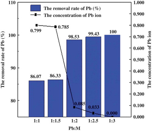
As shown in , along with the increase of proportion of dosing sodium sulfide, concentration of lead ion was reduced, whereas the lead recovery was improved in sodium silicate sample. When the ratio of dosing sodium sulfide and lead increased from 1.5:1 to 2:1, the concentration of lead ion in sodium silicate samples was reduced from 0.785 to 0.085 mg·L−1, whereas the removal rate of lead increased from 86.33% to 98.53%. The rate increased further with dosing sodium sulfide, the highest removal rate was 100% when dosing ratio was 3:1. We got clean sodium silicate and leaded precipitates after separation and filter.
Composition analysis and microstructure observation of lead sediment
The lead sediment that was obtained under the condition of dosage ratio was 3:1 was dried at 106 °C for 6 h. Then this lead precipitate was observed by field-emission scanning electron microscope (S-4800; Hitachi), the magnification was 250× and 5000×, respectively, as shown in and . Composition analysis was carried out at the same time, as shown in . X-ray diffraction (D/max-2500PC; Rigaku, Tokyo, Japan) pipe voltage was 5-50 keV, was used to clarify the crystal phases in lead precipitate, as shown in .
Figure 5. Scanning electron micrographs of black precipitate (magnification: (a) 250×, (b) 5000×).
Figure 6. EDX analysis of black precipitate generated by dosing Na2S to sodium silicate.
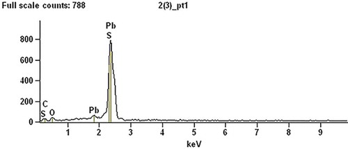
Figure 7. X-ray diffraction pattern of lead precipitate.
As can be seen from , the flocculent black leaded sulfide precipitate was generated after dosing sodium sulfide in the sodium silicate. An amount of crystal combined with each other; the crystalline structure has distinct density characteristics, which indicates that crystal growth was fast and it formed lead sulfide precipitation gradually. Under alkaline conditions, lead sulfide structure was very stable.
The black leaded sediment composition was analyzed by X-ray spectrometry; detailed analysis of the results is shown in .
We can see from that the black sediment was high-purity lead sulfide (PbS); a slight excess of C was due to adhesive tape of sample load bearing in test and it didn’t have effect on the PbS purity. Scanning electron microscopy analysis of the results showed that when sodium sulfide was used as a precipitant of leaded sodium silicate, the separation and recovery of lead effect was very satisfactory, and the lead sulfide precipitate had high purity. Sulfide precipitation method can not only prevent lead contamination caused by using leaded sodium silicate directly, but also realize recycling of lead resource to some extent by obtaining lead-free sodium silicate products.
As can be seen from , the peaks of lead sediment were clear and obvious. According to phase qualitative analysis, sample measured spectral line was compared with PDF standard spectral line. The composition of lead sediment was ascertained to be PbS and PbSO4, as shown in . There was little oxygen element in the sample; therefore, PbS was the majority of the composition.
X-ray diffraction pattern of hydrolysis residues
The compositions of waste CRT glass and hydrolysis residues were determined by X-ray diffraction (XRD); the results are shown in and .
Figure 8. X-ray diffraction pattern of waste CRT glass and hydrolysis residue.
From , we can see that waste CRT glass had the typical structure of glass. As shown in the , the peaks of hydrolysis insoluble substance were substantial and obvious, the peaks corresponding to the characteristic components were SiO2, PbO, Na2O, and so on. This suggests that internal network structure in leaded glass had been broken with the melting and dissolution processes. The differences of insoluble substance composition and structure characteristics were relatively obvious, which was helpful to reduce the processing difficulty of the hydrolysis residues.
Process route
The specific process route is shown in .
Figure 9. Process route of the technology.
In this study, the basic principle of the process route is as follows. With the help of production process of sodium silicate, the physical and chemical forms of waste CRT glass were changed, converting the CRT glass from the state of solid glass to the physical mixing of the compounds. The separation and recovery of lead metals proceeded effectively, and the clean sodium silicate products were obtained consequently.
The chemical composition (PbS) of recycled waste CRT glass meets the standard of level 4 or above of lead concentrate in YS/T319-2013 (National Development and Reform Commission). The technical indexes of recycled sodium silicate have reached the GB/T 4209-2008 (China National Standardization Management Committee) quality specification. The reaction proceeds with no need of severe condition such as vacuum. The craft and equipments are not complicated and satisfy the demand of practical production.
According to the previous research results, dealing with each 1 ton of waste CRT glass, will not only get 1.5 tons of sodium silicate, which costs around ¥1575 according to the Chinese market, but also recycled PbS containing 0.148 tons of lead metal as well, which costs around ¥2220 according to the Chinese market. However, the expenditure of the whole process including the chemical materials and energy consumption is around ¥1138, which is relatively low compared with other treatments. The foregoing analysis means dealing with each 1 ton of waste CRT glass will obtain a tremendous recovery value of ¥2657.
Conclusion
In this paper, we obtained an effective method to realize the recycle of the lead resource and produced sodium silicate through waste CRT glass. The research mainly focuses on the melting and dissolving of the sodium silicate frit and separation and recovery of lead in sodium silicate solution. On the basis of the experiments, we can get the following rules: the reaction rate of sodium silicate frit melted was 96.82% under the condition that the melting temperature was 1000 °C and water glass frit modulus was 2.0. The dissolution rate of sodium silicate frit was 44.725% under the condition that the melting temperature (self-built pressure of the system) was 175 °C (0.75 MPa), liquid-solid ratio was 1.5:1, and the dissolving time was 1 hr. Lead recovery rate of the sodium silicate reached 100% when adding the Na2S according to a particular ratio of Pb:M, which was 1:3. At this stage, the lead recovery rate of waste CRT glass was 43.30%. The subsequent processing of insoluble substance would further improve the lead recovery rate of waste CRT glass. Hydrolysis of insoluble substance research is currently underway.
Funding
The authors gratefully acknowledge the financial support from Tianjin Science and Technology Support Program (No. 14ZCDGSF00035).
Additional information
Funding
Notes on contributors
Biao Hu
Biao Hu is a professor, and Shuangshuang Zhao and Shuhao Zhang are master’s degree candidates at the School of Environmental Science and Safety Engineering, Tianjin University of Technology, P.R. China.
Related Research Data
References
- Andreola, F., L. Barbieri, A. Corradi, and I. Lancellotti. 2007. CRT glass state of the art, a case study: Recycling in ceramic glazes. J. Eur. Ceram. Soc. 27:1623–1629. doi:10.1016/j.jeurceramsoc.2006.05.009
- Andreola, F., L. Barbieri, A. Corradi, I. Lancellotti, R. Falcone, and S. Hreglich. 2005. Glass-ceramics obtained by the recycling of end of life cathode ray tubes glasses. Waste Manage. 25:183–189. doi:10.1016/j.wasman.2004.12.007
- Andreola, F., L. Barbieri, E. Karamanova, I. Lancellotti, and M. Pelino. 2008. Recycling of CRT panel glass as fluxing agent in the porcelain stoneware tile production. Ceram. Int. 34:1289–1295. doi:10.1016/j.creamint.2007.03.013
- Bernardo, E., and F. Albertini. 2006. Glass foams from dismantled cathode ray tubes. Ceram. Int. 32:603–608. doi:10.1016/j.creamint.2005.04.019
- Bernardo, E., R. Castellan, and S. Hreglich. 2007a. Sintered glass-creamics from mixtures of wastes. Ceram. Int. 33:27–33. doi:10.1016/j.creamint.2005.07.012
- Bernardo, E., G. Scarinci, and S. Hreglich. 2007b. Effect of time and furnace atmosphere on the sintering of glasses from dismantled cathode ray tubes. J. Eur. Ceram. Soc. 27:167–1643. doi:10.1016/j.jeurceramsoc.2006.04.144
- Birke, V., J. Mattik, and D. Runne. 2004. Mechanochemical reductive dehalogenation of hazardous polyhalogenated contaminants. J. Mater. Sci. 39:5111–5116. doi:10.1023/B:JMSC.0000039192.61817.dd
- Chen, M.J., F.S. Zhang, and J.X. Zhu. 2009. Lead recovery and the feasibility of foam glass production from funnel glass of dismantled cathode ray tube through pyrovacuum process. J. Hazard. Mater. 116:1109–1113. doi:10.1016/j.jhazmat.2008.04.084
- Chen, M.J., F.S. Zhang, and J.X. Zhu. 2010. Effective utilization of waste cathode ray tube glass-Crystalline silicotitanate synthesis. J. Hazard. Mater. 182:45–49. doi:10.1016/j.jhazmat.2010.05.135
- Goforth, D.E., L.R. Morse, and S.T. Gulati. 1994. Lead extraction from CRT glasses. In Proceedings of International Symposium Digest 94 Symposium, International Symposium Digest of Technical Papers. San Jose, CA, USA, June 14–16. SID:905–908.
- Grause, G., N. Yamamoto, T. Kameda, and T. Yoshioka. 2014. Removal of lead from cathode ray tube funnel glass by chloride volatilization. Int. J. Environ. Sci. Technol. 11:959–966. doi:10.1007/s13762-013-0286-0
- Guo, X., D. Xiang, G. Duan, and P. Mou. 2010. A review of mechanochemistry applications in waste management. Waste Manage. 30:4–10. doi:10.1016/j.wasman.2009.08.017
- Industry Council for Electronic Equipment Recycling (ICEER). 2004. Materials Recovery From Waste Cathode Ray Tubes (CRTs). Waste and Resource Action Programme. Report 70. Banbury, UK: Waste and Resource Action Programme.
- Ling, T.C., and C.S. Poon. 2011. Utilization of recycled glass derived from cathode ray tube glass as fine aggregate in cement mortar. J. Hazard. Mater. 192:451–456. doi:10.016/j.jhazmat.2011.05.019
- Méar, F, P.G. Yot, M. Cambon, R. Caplain, and M. Ribes. 2006a. Characterisation of porous glasses prepared from cathode ray tube (CRT). Powder Technol. 162:59–63. doi:10.1016/j.wasman.2005.11.017
- Méar, F, P.G. Yot, M. Cambon, R. Caplain, and M. Ribes. 2006b. The characterization of waste cathode-ray tube glass. Waste Manage. 26:1468–1476. doi:10.1016/j.wasman.2005.11.017
- Miyoshi, H., D.P. Chen, and T. Akai. 2004. A novel process utilizing subcritical water to remove lead from wasted lead silicate glass. Chem. Lett. 33:956–957. doi:10.1246/cl.2004.956
- Nnorom, I.C., O. Osibanjo, and M.O.C. Ogwuegbu. 2011. Global disposal strategies for waste cathode ray tubes. Resour. Conserv. Recy. 55:275–290. doi:10.1016/j.resconrec.2010.10.007
- Poon, C.S. 2008. Management of CRT glass from discarded computer monitors and TV sets. Waste Manage. 28:1499. doi:10.1016/j.wasman.2008.06001
- Pruksathorn, K., and S. Damronglerd. 2005. Lead recovery from waste frit glass residue of electronic plant by chemical-electrochemical methods. Korean J. Chem. Eng. 22:873–876. doi:10.1007/BF02705667
- Sasai, R., H. Kubo, M. Kamiya, and H. Itoh. 2008. Development of an eco-friendly material recycling process for spent lead glass using a mechanochemical process and Na2EDTA reagent. Environ. Sci. Technol. 42:4159–4164. doi:10.1021/es0719576
- Saterlay, A.J., S.J. Wilkins, and R.G. Compton. 2001. Towards greener disposal of waste cathode ray tubes via ultrasonically enhanced lead leaching. Green Chem. 3:149–155. doi:10.1039/b102671m
- Yot, P.G., and F. Méar. 2009. Lead extraction from waste funnel cathode-ray tubes glasses by reaction with silicon carbide and titanium nitride. J. Hazard. Materials. 172:117–123. doi:10.1016/j.jhazmat.2009.06.137
- Yu, J., E. Williams, M. Ju, and Y. Yang. 2010. Forecasting global generation of obsolete personal computers. Environ. Sci. Technol. 44:3232–3237. doi:10.1021/es903350q
- Yuan, W., J. Li, Q. Zhang, and F. Saito. 2012. Innovated application of mechanical activation to separate lead from scrap cathode ray tube funnel glass. Environ. Sci. Technol. 46:4109–4114. doi:10.1021/es204387a
- Yuan, W., J. Li, Q. Zhang, F. Saito, and Y. Bo. 2013a. A novel process utilizing mechanochemical sulfidization to remove lead from cathode ray tube funnel glass. J. Air Waste Manage. Assoc. 63:418–423. doi:10.1080/10962247.2012.701194
- Yuan, W., J. Li, Q. Zhang, F. Saito, and Y. Bo. 2013b. Lead recovery from cathode ray tube funnel glass with mechanical activation. J. Air Waste Manage. Assoc. 63:2–10. doi:10.1080/10962247.2012.711796