ABSTRACT
This paper reports development and testing of a novel cross-flow wet electrostatic precipitator (WESP), recently patented at Ohio University, that utilizes vertical columns of permeable material in the form of polypropylene ropes placed in a cross-flow configuration within a flue gas stream. The cross-flow design has large surface area, which provides scrubbing action; therefore, it has the potential for removing multiple pollutants, including particulates, gases, vapors, and mists. In this new method, the ropes are kept wet by the liquid (water) introduced from the top of the cells running downward on the ropes by capillary action, making the permeable materials act as the ground electrode for capturing particles from the flue gas. Preliminary testing has shown an efficiency of well above 80% using two cells and three sets of discharge electrodes. Since the material of construction is primarily corrosion-resistant polymeric material, both weight and cost reductions are expected from this new design.
Implications: The newly invented cross-flow WESP exhibit particulate collection efficiency of well above 80% when introduced in particulate-laden exhaust flow. This value was obtained using a two cells and three discharge electrodes configuration. The electric field strength has a substantial effect on the collection efficiency. Also, the pressure drop test results indicate that there is a potential to increase the collection area, which, in turn, will increase the collection efficiency further.
Introduction
Electrostatic precipitators (ESPs) have commonly been used in collecting particulates of a wide range of sizes in gas streams (by charging), starting with one of the first patents awarded to F. Cottrell in 1908. They also can operate in a wide range of pressures, flow rates, and gas temperatures. ESPs are durable and easy to operate; however, the dry precipitators might not be suitable for collecting fine particles (Altman et al., Citation2001a, Citation2001b; Flagan and Seinfeld, Citation1988). In fact, dry ESPs have not been able to address successfully the challenges of collecting the particles in the diameter range of 0.1–2 mm due to the limitation on charging mechanisms of this range of the particle sizes (Flagan and Seinfeld, Citation1988; Chen et al., Citation2014). And in dry precipitators, this limitation is exaggerated because of lower corona power levels caused by the accumulated ash layer on the collector electrodes, which increases the resistivity (Altman et al., Citation2001a, Citation2001b).
One of the factors that affect particle charging is corona generation. Some experimental work has been done in the past in estimating corona onset gradient (Peek, Citation1920). An empirical expression was derived using the results of a coaxial wire/cylinder geometry subjected to AC voltages. The expression is given below:
where Es is corona onset gradient, ro is the wire radius, and A, B, and C are constants. Gas ionization process is another factor that affects particle charging following corona and is described by Townsend’s law (Braithwaite, Citation2000) by relating the ionization mean free path to the total scattering mean free path, in which free electrons are accelerated by an electric field, collide with gas molecules, and consequently free additional electrons, which accelerate further, are generated, resulting in an avalanche multiplication that permits electrical conduction through the gas.
where α is Townsend’s ionization coefficient, p is pressure, E is electric field in volts per meter, and the A and B are properties of the gas.
Wet precipitators were developed in order to improve the performance of ESPs in removing particulates along with acid aerosols. Also, wet ESPs are expected to provide stronger corona power compared with dry ESPs due to the fact that the accumulated fly ash is washed off the collector plates, preventing back corona. This effect improves the collection efficiency of the fine particles by more effective particle charging (Altman et al., Citation2001a, Citation2001b; Chang and Hsunling, Citation1999). Furthermore, because acid aerosols are usually soluble in water, after collection, it is easier to remove them by flowing water on the collector electrodes in wet ESPs (Bayless et al., Citation2005; Bologa et al., Citation2009).
However, when it comes to the large-scale wet ESPs, there are some obstacles preventing them from operating effectively. For instance, the collector electrodes, which are usually a continuous sheet of metal or plastic, are not uniformly washed with the flushing water. Due to the surface tension effects and (collector) plate’s surface imperfections, the water passing over the plates’ surface tends to bead, resulting in channeling and formation of dry spots of collected particles. To eliminate this issue, a huge amount of water should be introduced to the plates, which is not an effective way to solve this problem, because the mist, which ends up flowing with the gas, is more conductive than the typical gas itself, creating a more conductive path to ground, thus shorting out the field (Bayless et al., Citation2005; Pasic, Citation2006). In addition, water streams and splashing can also potentially provide path to ground from high-voltage discharge electrodes to the collection electrodes. To prevent this (grounding) issue, the collector electrodes are usually cleaned when the field voltage is reduced or terminated. Another important weakness of the traditional wet ESPs is corrosion, which is due to low pH from the acid gas collection. In the presence of chlorides, corrosion potential is worse. All this requires the collector electrodes to be made of expensive alloys. The other issue with the use of traditional ESPs and other pollution control methods is the parasitic load on coal-based power production systems while treating multiple pollutants in the exhaust gas stream. Therefore, high collection efficiency along with a capability of treating multiple pollutants along with waste heat recovery could make pollution control devices more cost-effective.
To address these problems, Pasic et al. invented a membrane-based wet electrostatic precipitation, which used hydrophilic material (polypropylene) to better improve the wet ESPs (Pasic et al., Citation2001). This hydrophilic material uniformly dispersed the water introduced from the top of the membranes throughout the membranes by capillary action. This had a potential to eliminate spraying (resulting in continuous electric field application) as well as dry spots resulting from water beads and channels while flowing over continuous surfaces, such as the metal plates. Moreover, the study conducted on membrane-based electrostatic precipitator by Shah and Cain showed a successful 5-yr performance of membrane WESP. They also used polypropylene as the membrane material. Based on their study, no damage (including from ultraviolet [UV] radiation) was reported and the unit operated essentially trouble-free for almost 5 yr (Shah and Caine, Citation2008).
Chao Huang and his colleagues proposed another method in which grooved polyvinyl chloride (PVC) plates were used as collecting electrodes. As reported, the grooves helped to have higher water film ratio compared with untreated PVC plate, which resulted in higher corona current and dust collection efficiency (Huang et al., Citation2014).
For corrosion issues, the membrane materials appeared to be corrosion-free after a relatively long use (Pasic, Citation2006). Furthermore, using continuously wetted membranes, water make-up could be eliminated with the help of gas condensation on and in the vicinity of membranes. The removal of the liquids in flue gas would also increase gas transparency and would result in corrosion and damage alleviation of gas pipeline and chimney (Pasic, Citation2006; Huang et al., Citation2014).
Introducing membrane-based wet electrostatic precipitation (Pasic et al., Citation2001; Bayless et al., Citation2004), and employing different materials other than solid continuous metal or plastic plates as collector electrodes, such as terylene and polypropylene, solved some of the problems mentioned with traditional wet ESPs. Nevertheless, these recent ideas of using membranes and different materials are lacking some of the desired characteristics. For instance, the collection surface area is still the same as metal or plastic collector electrodes, and also the configuration of the ESP pilots are still the same, occupying a huge amount of space when installed.
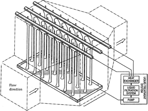
To address the needs mentioned above, a new wet ESP is presented here, which utilizes vertical columns of permeable material as collector surfaces. These collectors are in the form of polymer ropes or strands placed in a cross-flow configuration within a flue gas stream (). A downward-flowing liquid (typically water) on the ropes or strands keeps them fully wetted by capillary action, since the material is permeable. Such materials consist of, but are not limited to, inexpensive hydrophilic polypropylene ropes, which are commercially available. These 5–10-mm permeable ropes act as the ground electrode. They also resist chemicals, relatively high temperatures, and abrasion and are mechanically strong. Sets of discharge electrodes are placed in the front and back of the wet columns based on the test configuration. As the flue gas moves through the wet permeable columns, particles are charged by the discharge electrodes and then collected on these columns.
It is worth mentioning that as compared with cross-flow WESP techniques, in the conventional ESP, which are also called parallel-flow systems, electrodes (both collection and charging) are set parallel to the gas flow. Technologies in which the electrodes are set perpendicular to the gas flow are very new and still under development. The first of such a design in dry ESP applications, passing particulate-laden gas through a set of metal screens, was suggested by H. Pasic (Pasic, Citation2004, Citation2005).
The new cross-flow WESP technology presented here is the first successful attempt to use the wet cross-flow ESP, which, in the initial study, resulted in the particle removal efficiency of 81.38% with (only) two cells. The distinguishing feature of this new design is the large collection area, which is needed in any scrubbing application. Because of the high surface area, the hot unsaturated gases are cooled, and the water is heated in a process that is similar to a direct contact cross-flow heat exchanger. The energy extracted from the hot gases by the water can be recovered by heating incoming combustion air. The water is then recirculated, as shown in . In power plants, water from flue gas is condensed on the wet columns and the makeup water requirement is minimized. In addition to large collection area, the weight of cross-flow cells is also considerably less than the metal plates used in horizontal ESPs.
Experimental study
Cross-flow ESP setup
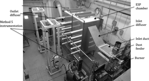
In order to investigate the performance of the cross-flow WESP, an experimental setup was designed and fabricated. To conduct the experiments, the existing pilot ESP system of Ohio University’s ESP laboratory (shown in ) was used. The system consisted of inlet diffuser, ESP housing/chamber, and outlet diffuser. The inlet (duct) of the system contained propane gas burners and a dust feeder with a dust delivery system. The outlet diffuser was connected through more duct work to the variable-frequency drive fan, which was capable of generating velocities up to 20 m/sec across the cross-flow field. The overall length, height, and width of this system were 7.3, 3, and 1.2 m, respectively. The ESP chamber was 2.4 m long, 1.8 m high, and was 0.6 m wide.
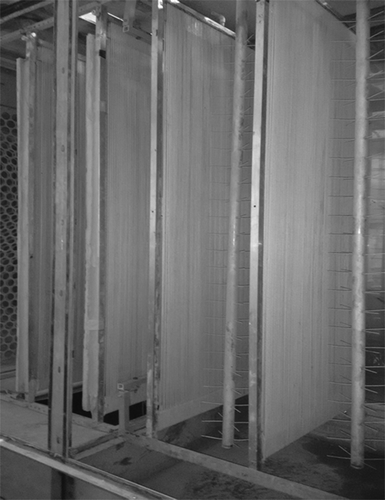
The cross-flow setup consisted of a number of 0.6 m wide, 1.8 m high, and 0.0254 m (25.4 mm) thick cells. Each cell had two rows of inexpensive polypropylene ropes, 0.005 m (5 mm) in diameter, which ran vertically up and down, creating a number of loops across each cell. These cells were housed in the ESP chamber with a 0.4-m gap between them, as shown in and .
The ropes were kept wet using a water delivery system, shown in , fabricated on the top of each cell, through which water was flowing downward on each column of the ropes. Flow meters were used for each cell in order to be able to adjust the water flow rate for each of them separately. After the cells were in place and the water supply hoses were attached to the water entry ports on each cell, all gaps around the cross-flow cells were sealed to prevent the particle-laden flow bypassing the cross-flow cell.
A 70-kV Transformer-Rectifier unit (NWL PowerPlus Series model 102462 REV B; Bordentown, NJ, USA) was used to supply the power to the discharge electrodes with negative polarity (see , , and ). As shown in , three pairs of rigid discharge electrodes were installed. One pair of electrodes before first cell, one in between the two cells, and one after the second cell. Each electrode comprised a 0.05 m (50 mm) tube with 0.089 m (89 mm) long spikes. The distance between each row of electrodes and cell was 0.127 m (127 mm), whereas distance between the two electrodes in each row was 0.254 m (254 mm).
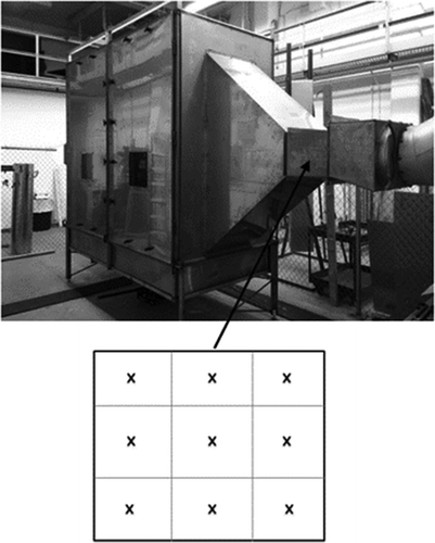
The particulate-laden gases (ambient air and particulates) were introduced in the ESP chamber at 54.4 °C through variable-frequency-induced draft fan. The average flow velocity was kept at 3 m/sec in the chamber. Due to the geometry of chamber, flow was expected to be turbulent. The inlet particulate concentration was kept approximately at 30 mg/m3 and was measured using gravimetric method and a PM (particulate monitoring) unit (Thermo Scientific MIE ADR-1500), which measures the particle mass concentration instantaneously using light scattering photometry method (Thermo-Fisher Scientific, Citation2013). A second PM unit was used to measure the average particulate concentration in the outlet. The particulate concentration was measured at nine spots (for 3 min for each spot) over the inlet and outlet cross-sections (0.6 m wide and 0.3 m high) as shown in , and the average of these nine points was taken as the particulate concentration in the inlet and the outlet. Knowing the average concentrations of the inlet and the outlet, the particulate collection efficiency was calculated using the following formula (Kim et al., Citation2011):
where Cin is the average particulate concentration in the inlet and Cout is the average particulate concentration in the outlet. In order to do isokinetic sampling using the PM unit, first the flow velocity was measured using velocity probes at aforementioned nine spots. The diameter of the sampling nozzles of the PM unit were selected, using eq 4, based on the known flow rate of 3.5 L/min for the PM unit.
where V is the measuring spot’s gas flow velocity, A is nozzles cross-sectional area, is PM unit’s sampling flow rate, and d is nozzle dimeter.
The fly ash added to the airflow was analyzed by a particle size analyzer. It was determined that the maximum, minimum, and the average diameters were 8.84, 1.61, and 3.75 microns, respectively.
Test
Impaction and efficiency tests were conducted with one-cell and two-cell configurations. In impaction tests, no electrical field was applied; therefore, no driving force was there for the particulates except the gas flow itself, which caused the particles to impact and stick on the wet ropes on their way passing through the columns of ropes toward outlet. It is noteworthy that the flow caused the columns of ropes to vibrate, which resulted in capturing some of the particles that would normally escape through the spacing between the columns. In efficiency tests, electrical field was applied using the discharge electrodes shown in . The tests performed are listed in .
Table 1. Test matrix.
The testing of the cross-flow collection efficiency must take into account particles that drop out and collect on the floor and walls irrespective of the electric field. Therefore, dropout tests were carried out prior to conducting impaction and efficiency tests. The dropout fraction was determined experimentally to be 15%. The tests conditions are listed in .
Table 2. Test conditions.
In the efficiency tests with electric field applied, the tests configurations were designed in a way that the effect of the single electrical field in front of the cell would be measured first, followed by tests using two electrical fields (generated by discharge electrodes in the front and behind the cell). These different configurations will be referred to by the symbols “C” for each cell and “E” for discharge electrode. Therefore, a single cell with discharge electrodes in the front and back of the cell will be referred to “ECE” configuration.
Results and discussion
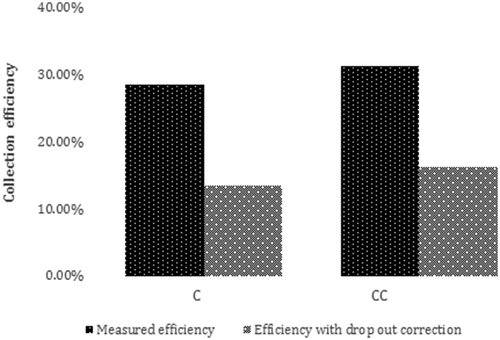
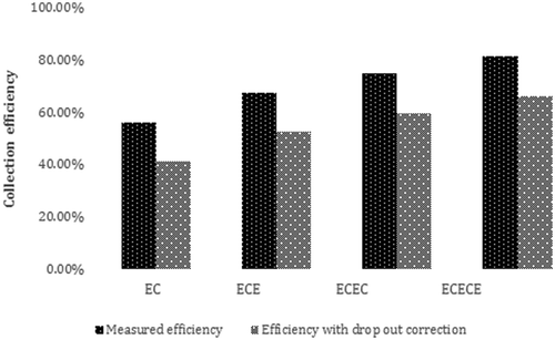
shows impaction efficiency with one and two cells with and without dropout correction. For one and two cells, the values noted were 28.5% and 31.26% with dropout included and 13.50% and 16.26% with dropout correction. Therefore, by increasing the number of the cells from one to two, an increase of 20.44% in particulate collection efficiency was observed. shows the efficiency for different configurations when the electrical field was applied. Comparing the impaction tests results () with the efficiency tests results (), it is evident that the particulate collection efficiency increased noticeably when the electricity was applied. A significant increase of 204% was observed in the efficiency (measured collection efficiency 41%) when one set/pair of the discharge electrodes (two electrodes in a row as shown in ) was added to the one-cell impaction test (C → EC). As can be seen in , by adding the second set of the discharge electrode behind the first cell, the collection efficiency improved by 27.82%. This means the cell captured 19.34% of the remaining 59% particulate when another electrical field was applied behind it.
To compare efficiencies of the cross-flow ESP with the conventional wet ESP, it was assumed that the conventional ESP has the same height and width
as the cross-flow ESP. Assuming further that it has three collection electrodes that make two gas passages, each one having standard width
with discharge electrodes set in the middle. Let the gas speed be the same in both ESPs, i.e., let
. In coal-burning industries, particulates’ migration velocity ranges between 0.04 and 0.2 m/sec (U.S. Environmental Protection Agency [EPA], 1998). Assuming it’s very high value of
and using the Deutsch-Anderson equation
, with the gas flow rate
and with the total particle collection area of
, where L is the ESP length, in order to have the same dust collection efficiency
, one finds that the conventional wet ESP’s length needs to be L = 2.55 m, i.e., its overall volume is about four and a half times that of the cross-flow ESP when compared with ECE setup(L = 0.58 m).
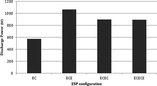
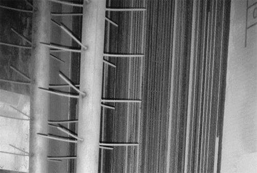
Another 14.07% increase in efficiency (measured collection efficiency 59.80%) was observed when the second cell was set up (ECEC). However, the discharge power decreased by 15.62%, as can be seen in . Furthermore, when the next set of the discharge electrodes were in place (ECECE), an increase of 11% was observed in the efficiency compared with the ECEC configuration and the highest collection efficiency of 81.38% was obtained, whereas a small decrease in the discharge power was observed. shows one of the cells after particle collection.
Based on the results presented, it is clear that the discharge power has a significant effect on the collection efficiency. So, it is expected that with having the discharge power improved for ECEC and ECECE, considerably higher particulate collection efficiency would be reachable. This aspect is under investigation.
Pressure drop
In contrast to conventional (dry/wet) ESPs where the flow is parallel to the collection plates, the new technology presented here exploits the particle-laden gas flow perpendicular to the collection electrodes. Therefore, pressure drop across cells becomes an important parameter.
In the present study, pressure drop was measured two ways: (1) using an S-type pitot tube available in our laboratory as part of standard method 5 probes (built by APEX Instruments, Fuquay-Varina, NC); and (2) with a digital manometer at four points in cross-flow setup (see ). The values were then compared with the pressure drops measured for the traditional horizontal ESP setup. While making these measurements, test conditions such as inlet and outlet duct sizes, ESP chamber size, and flow velocity were kept the same for both (cross-flow and horizontal ESP) setups ().
Table 3. Pressure measured at the shown points (Pascal).
As seen, the pressure drop between the inlet and the outlet (1 and 4) is the same (473.2 Pa) for both the cross-flow and horizontal ESP, which shows that there is a potential to increase the collection surface area by having additional columns of the collector ropes, which has a potential to increase collection efficiency further without significant pressure drop. It is noteworthy that the pressure drop is same for both cross-flow and horizontal ESP setups, although some differences were expected. However, the compact depth of the cross-flow cell produces very small pressure drop, which was verified by using analytical calculations for banks of cylindrical surfaces.
Conclusions
The newly invented cross-flow WESP was investigated experimentally in this study. And the collection efficiency of well above 80% was obtained using the two cells and three discharge electrodes configuration (ECECE). It was observed that the discharge power has a substantial effect on the collection efficiency by charging the particulates more effectively. This was reflected in a noticeable increase of 204% after applying the electric field in front of the first cell. Also, the pressure drop test results indicate that there is a potential to increase the collection area by having additional polypropylene ropes in each cell, which will result in larger surface area for the particulates to impact on and higher corona power as well, thus increasing the collection efficiency further.
Acknowledgment
The authors would like to thank the anonymous referees for providing useful, constructive, and insightful feedback that resulted in a significant improvement of the original manuscript.
Funding
This work is supported through funds provided by the Babcock and Wilcox Company (GR-020-3200-08150), Ohio University Research Office, and Ohio University’s Russ College of Engineering and Technology.
Additional information
Funding
Notes on contributors
M. Ali
M. Ali, H. Pasic, and K. Alam are professors in the Department of Mechanical Engineering at Ohio University, in Athens, OH, USA.
H. Pasic
M. Ali, H. Pasic, and K. Alam are professors in the Department of Mechanical Engineering at Ohio University, in Athens, OH, USA.
K. Alam
M. Ali, H. Pasic, and K. Alam are professors in the Department of Mechanical Engineering at Ohio University, in Athens, OH, USA.
S.A.N. Tiji
S.A.N. Tiji and N. Mannella are research assistants in the Department of Mechanical Engineering at Ohio University, in Athens, OH, USA.
N. Mannella
S.A.N. Tiji and N. Mannella are research assistants in the Department of Mechanical Engineering at Ohio University, in Athens, OH, USA.
T. Silva
T. Silva and T. Liu are air quality control system research engineers at the Babcock and Wilcox Company, in Barberton, OH, USA.
T. Liu
T. Silva and T. Liu are air quality control system research engineers at the Babcock and Wilcox Company, in Barberton, OH, USA.
References
- Altman, R., W. Buckley, and I. Ray. 2001a. Wet electrostatic precipitation demonstrating promise for fine particulate control—Part II. Power Eng. 105:42–4.
- Altman, R., G.O. Pepri, W. Buckley, and I. Ray. 2001b. Wet electrostatic precipitation demonstrating promise for fine particulate control—Part I. Power Eng. 105:37–9.
- Bayless, D.J., L. Shi, G. Kremer, B.J. Stuart, J. Reynolds, and J. Caine. 2005. Membrane-based wet electrostatic precipitation. J. Air Waste Manage. Assoc. 55:784–91. doi:10.1080/10473289.2005.10464658
- Bayless, D.J., M.K. Alam, R. Radcliff, and J. Caine. 2004. Membrane-based wet electrostatic precipitation. Fuel Process. Technol. 85: 781–98. doi:10.1016/j.fuproc.2003.11.025
- Bologa, A. H.R. Paur, H. Seifert, T. Wascher, and K. Woletz. 2009. Novel wet electrostatic precipitator for collection of fine aerosol. J. Electrostat. 67: 150–53. doi:10.1016/j.elstat.2009.01.059
- Braithwaite, N.St.J. 2000. Introduction to gas discharges. Plasma Sources Sci. Technol. 9:517–27. doi:10.1088/0963-0252/9/4/307
- Chang, C.L., and B. Hsunling.1999. An experimental study on the performance of a single discharge wire-plate electrostatic precipitator with back corona. J. Aerosol Sci. 30: 325–40. doi:10.1016/S0021-8502(98)00064-0
- Chen, T.M., C.J. Tsai, S.Y. Yan, and S.N. Li. 2014. An efficient wet electrostatic precipitator for removing nanoparticles, submicron and micron-sized particles. Sep. Purif. Technol. 136: 27–35. doi:10.1016/j.seppur.2014.08.032
- Flagan, R.C., and J.H. Seinfeld. 1988. Fundamentals of Air Pollution Engineering. Upper Saddle River, NJ: Prentice Hall Publications.
- Huang, C., X. Ma, M. Wang, Y. Sun, C. Zhang, and H. Tong. 2014. Property of the PVC dust collecting plate used in wet membrane electrostatic precipitator. IEEE Trans. Plasma Sci. 42:3520–3528. doi:10.1109/TPS.2014.2359973
- Thermo-Fisher Scientific. 2013. Instruction Manual—ADR-1500, Particulate Monitor, Part Number 108836-00. Franklin, MA: Thermo-Fisher Scientific.
- Kim, H., B. Han, Y. Kim, K. Hwang, W. Oh, S. Yoo, and T. Oda. 2011. Fine particle removal performance of a two-stage wet electrostatic precipitator using a nonmetallic pre-charger. J. Air Waste Manage. Assoc. 61:1334–43. doi:10.1080/10473289.2011.603994
- Lee, W.J., S.J. Chen, M.C. Liow, L.C. Wang, and K.L. Huang. 1998. Removal efficiency of PAHs by the electrostatic precipitator and wet scrubber. J. Aerosol Sci. 29: S1081–S1082. doi:10.1016/S0021-8502(98)90723-6
- Pasic, H. 2004. Sieving electrostatic precipitator. Presented at IX International Conference on ESP for International Society for Electrostatic Precipitation, Kruger Park, South Africa, May 17–21, 2004.
- Pasic, H. 2005. Electrostatic sieving precipitator. U.S. patent no. 6,878,192.
- Pasic, H. 2006. Membrane tubular wet electrostatic precipitators. Technol. Rev. 43(9):16–18. doi:10.1016/S0015-1882(06)71003-5
- Pasic, H., M.K. Alam, and D.J. Bayless. 2001. Membrane electrostatic precipitator. U.S. patent no. 6,231,643 B1. doi:10.1080/10473289.2001.10464372
- Peek, F.W. 1920. Dielectric Phenomena in High Voltage Engineering, 52–80. New York: McGraw-Hill.
- Shah, H., and J.C. Caine. 2008. Next generation wet electrostatic precipitator. In Proceedings of the International Technical Conference on Coal Utilization and Fuel Systems, Clearwater, FL, June 1–5, 2008. https://www.southernenvironmental.com/assets/membrane-wesp_rev4.pdf ( accessed March 19, 2016).
- U.S. Environmental Protection Agency. 1998. ESP Design Parameters and Their Effects on Collection Efficiency. https://www.neundorfer.com/FileUploads/CMSFiles/ESP%20Design%20Parameters(0).pdf ( accessed January 21, 2016).

