ABSTRACT
Emissions from flares constitute unburned hydrocarbons, carbon monoxide (CO), soot, and other partially burned and altered hydrocarbons along with carbon dioxide (CO2) and water. Soot or visible smoke is of particular concern for flare operators/regulatory agencies. The goal of the study is to develop a computational fluid dynamics (CFD) model capable of predicting flare combustion efficiency (CE) and soot emission. Since detailed combustion mechanisms are too complicated for (CFD) application, a 50-species reduced mechanism, LU 3.0.1, was developed. LU 3.0.1 is capable of handling C4 hydrocarbons and soot precursor species (C2H2, C2H4, C6H6). The new reduced mechanism LU 3.0.1 was first validated against experimental performance indicators: laminar flame speed, adiabatic flame temperature, and ignition delay. Further, CFD simulations using LU 3.0.1 were run to predict soot emission and CE of air-assisted flare tests conducted in 2010 in Tulsa, Oklahoma, using ANSYS Fluent software. Results of non-premixed probability density function (PDF) model and eddy dissipation concept (EDC) model are discussed. It is also noteworthy that when used in conjunction with the EDC turbulence-chemistry model, LU 3.0.1 can reasonably predict volatile organic compound (VOC) emissions as well.
Implications: A reduced combustion mechanism containing 50 C1–C4 species and soot precursors has been developed and validated against experimental data. The combustion mechanism is then employed in the computational fluid dynamics (CFD) of modeling of soot emission and combustion efficiency (CE) of controlled flares for which experimental soot and CE data are available. The validated CFD modeling tools are useful for oil, gas, and chemical industries to comply with U.S. Environmental Protection Agency’s (EPA) mandate to achieve smokeless flaring with a high CE.
Introduction
Flares are important safety device for pressure relief from process units and storage vessels, especially during start-up, shut-down, and malfunction (SSM) situations. They are used to discharge vent gases in an environmentally safe manner into the atmosphere. Flaring is extensively used to dispose waste flammable gases in the refinery, chemical processing, and oil/gas industries. However, flaring process is complicated, since its performance is affected by many operating, design, and meteorological conditions. In many cases, flares are operated with excessive air and steam assists to suppress smoke at the expense of combustion efficiency (CE) and destruction efficiency (DE) (U.S. Environmental Protection Agency [EPA], Citation1991; Pohl and Soelberg, Citation1986; Pohl, Citation1984; Pohl, Citation1985), Undesirable pollutants are also formed from the combustion process. For instance, flares account for 61% of the highly reactive volatile organic compound (HRVOC) emissions based on the 2007 HRVOC special emissions inventory (Texas Commission on Environmental Quality [TCEQ], Citation2011). Combustion chemistry indicates that many intermediate species, including VOCs, hydrogen oxides (HOx), nitrogen oxides (NOx), carbon monoxide (CO), and soot, are also formed (Kindzierski, Citation1999).
Validated CFD models are important for parametric studies and flare optimization purposes. In order to model the flaring process using computational fluid dynamics (CFD), combustion mechanisms are required. For light hydrocarbon combustion, the two most commonly accepted combustion mechanisms are GRI 3 (Smith et al., Citation2011) and USC II (Wang et al., Citation2007). GRI 3.0 (Smith et al., Citation2011) has 53 species optimized for methane combustion. The USC II mechanism uses 111 species, including species and reactions required for soot formation and oxidation. For soot prediction, the Moss-Brookes-Hall model is only available in ANSYS Fluent (ANSYS Inc., Citation2011) when C2H2, C2H4, and C6H6 are present in the gas phase species list. On the other hand, a few aspects of natural gas combustion chemistry are not described by GRI-Mech 3.0; these include soot formation and the chemistry involved in the selective noncatalytic reduction of nitric oxide (NO). In current study, the USC II mechanism was used as the base mechanism. The computational cost required to solve turbulence-chemistry problems increases exponentially with increase in the number of elementary reactions (Lu and Law, Citation2005). This intricacy has motivated the development of reduced mechanisms that retain a smaller set of species and reactions required to capture the essential features of combustion chemistry (Hautman et al., Citation1981). Therefore, a 50-species reduced mechanism, LU 3.0.1, was developed using CHEMKIN-PRO (Reaction Design, Citation2013). LU 3.0.1 is capable of handling C4 hydrocarbons and soot precursor species (C2H2, C2H4, C6H6).
The TCEQ flare tests were conducted at the John Zink R&D facility in Tulsa, OK in Collaboration with UT, Austin in September 2010, using propylene/Tulsa Natural Gas/nitrogen as vent gases under open-air conditions. At the conclusion of this study, the relationship between flare design, operation, vent gas lower heating value (LHV) and flow rate, destruction and removal efficiency (DRE), and combustion efficiency (CE) were determined (Allen and Torres, Citation2011; EPA, 2012).
Fortner et al. (Citation2012) studied flare combustion characteristics in 2010 TCEQ flare tests and found that propylene mix flare plumes have a significant black carbon (soot) content that is sensitive to air and steam assist levels. Input data in the current simulation study include the geometry of the flares used in the tests, and meteorological/operating data are available from the flare test data acquisition system. The numeric soot emission data for certain test series reported in the 2010 TCEQ Flare Study Particulate Appendix (TCEQ, Citation2011; Fortner et al., Citation2012; E.C. Fortner, personal communications, 2015) were also acquired. These data sets serve as the foundation to check and possibly calibrate the CFD modeling for flare efficiency and soot/VOC emissions.
Literature survey
Detailed experiments were conducted on propane flames in a cross-flow of air to study flame structures, species concentration, and temperature profiles (Huang and Chang, Citation1994; Huang and Yang, Citation1996). Results of flare research performed by the Alberta Research Council (ARC) show the significance of crosswinds on flare efficiencies (Strosher, Citation1996, Citation2000). Extensive experimental research on full-scale industrial flares has been conducted at various vent gas heating values and flow rates (Torres et al., Citation2012) for which flare efficiencies and incomplete combustion products have been investigated. Researchers have attempted to characterize the particulate emissions and behavior of diffusion flames more closely on a laboratory scale (McEwen and Johnson, Citation2012). Soot formation in flares has been an ongoing research for the last few decades and has gained more attention recently due to the environmental concerns and ensuing regulations. Modeling efforts in this area have been carried out using different approaches (Busupally and De, Citation2016, Kronenburg et al., Citation2000; Thomas et al., Citation2008). Further, numerical simulations of different flames in a cross-flow air has been conducted using various combustion and turbulence models to study the effect of fuel and cross-flow velocities on pollutant properties (Lawal et al., Citation2010, Citation2013; Aboje et al., Citation2015). The present work discusses two different models in CFD to predict flare efficiency and soot emission using the developed combustion mechanism LU 3.0.1.
Reduced reaction mechanism
Preliminary selection of species
A species list was made from LU 1.0, LU 1.1, and LU 2.0 mechanisms (Lou et al., Citation2011; Lou, Chen et al., Citation2012; Lou, Martin et al., Citation2012), which were developed earlier to study the formation of VOCs and NOx from the combustion of light hydrocarbons. A common 34-species set from both LU 1.1 and LU 2.0 containing important species related to the generation of VOCs, including HCHO, CH3CHO, CH2CHO, was retained in the new mechanism. In order to include the soot precursor species (C6H6 and C6H5) for use in the Fluent Moss-Brooks model, the species required for the formation of benzene ring were identified based on literature survey (McEnally et al., Citation2006; Slavinskaya and Frank, Citation2009; Davis et al., Citation1999) and added to form the initial 50-species list.
The initial 50-species list includes C1–C3 hydrocarbons such as methane (CH4), acetylene (C2H2), ethylene (C2H4), ethane (C2H6), propene (C3H6), and propane (C3H8), as most of the modeling work would be performed with these fuels. Additional species, such as propyne (C3H4) and butadiene (C4H6), are also included, as their decomposition will lead to propargyl (C3H3), allyl (C3H5), and butadienyl (C4H5) radicals involved in the formation of the first aromatic ring. Also the formation of monosubstituted aromatics from small molecules needs to be considered (Blanquart, Citation2008; Frenklach, Citation2002). The formation of C3 species from small hydrocarbons is achieved through a series of reactions. It was proposed that the methyl addition to acetylene leads to the formation of both C3H4 and C3H5 isomers (Davis et al., Citation1999). Another possibility for the initial ring formation is the reaction between propargyl (C3H3) and acetylene (C2H2) to form a cyclopentadienyl radical (cC5H5) (Frenklach, Citation2002). This pathway combines the advantages of the two reactant types discussed: highly stable radical, propargyl, and the most abundant building block, acetylene. Cyclopentadienyl, once formed, reacts rapidly to form benzene (Melius et al., Citation1996). However, this list can be further checked using CHEMKIN to determine individual species’ contribution to the fuel combustion and soot precursor formation.
The formation and growth of aromatic species bridge the chemistry in the main combustion zone and soot formation. In addition, aromatic molecules are toxic and subject to environmental regulations. The primary focus is on the formation of the first aromatic ring from small aliphatics, because this step is considered to be the rate-limiting step in the reaction sequence to larger aromatics (Colket et al., Citation1989).
Reaction Path Analyzer
The Reaction Path Analyzer (RPA) is a feature in CHEMKIN to provide visualization of the inner relationship of the chemistry model and to provide a primary understanding of reaction mechanism dependencies. The reaction path diagram displays species as well as reaction pathways connecting the species. The relative size of the connecting pathways is related to the relative contribution of that pathway to the net rate of production of the species. Path widths with the minimum rate of production correspond to the smallest line thickness, and the path widths with the maximum rate of production are scaled to the largest allowed line thickness. RPA helps identify main intermediates during reaction path and eliminate any species with negligible contributions, thereby validating the species list.
In the current study, reaction paths between fuel components and the major products (CO, CO2, HCHO, C6H6, C6H5) were analyzed; the major contributing reactions and participating species were identified. The inlet pressure and temperature of the reactor were 1 atm and 298 K, respectively, and an equivalence ratio of 1 was maintained throughout the evaluation of the RPA. CHEMKIN results for various reaction paths can be shown in a diagram with a maximum number of species. For propylene fuel, aC3H5 (allene) and C2H3CHO (acrolein) are the major intermediates for combustion of C3H6. The important reaction paths for C4H10, C3H8, and C2H6 to conversion carbon dioxide (CO2) and CO with 15 species were selected through RPA.
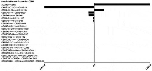
The major intermediate species for combustion of C1–C4 light hydrocarbons are C2H5, n-C3H7, p-C4H9, aC3H5, C2H3CHO, CH3O, and CH3OH. shows the absolute rate of production of soot precursor species, C6H6, from various intermediate species. From , the major intermediates to be considered for the formation of soot precursors C6H6 are C3H3, C5H5, and C6H5O. The effects of other intermediates are negligible and hence not included in the current mechanism.
Relatively minor species in the mechanism such as H2O2, HCCOH, C2H, and C2O are removed. 1,3-Butadiene (C4H6), which is both a fuel and an EPA-classified carcinogen has been added to this list. Also, 1-butene (C4H81), a HRVOC defined by the TCEQ, is added to the 50 species list. shows the final 50-species list, and shows important C4 species and the soot precursors.
Table 1. The 50-species list for LU 3.0.1 combustion mechanism.
Table 2. C4 species and soot precursors.
Reaction rate analysis
To validate the species list, the full USC II mechanism was run as a reference combustion model in CHEMKIN. Analysis of the important species was done as a first step by ranking the intermediate species based on their rates of production and destruction, and then the reaction path analysis was done for both reactants and products.
Perfectly stirred reactor (PSR) model is a common method for testing and developing chemical reaction mechanisms and was found very useful in studying kinetics (Bowman et al., Citation1973). It is considered the best experimental environment, where species undergoing chemical reactions are assumed to have infinitely fast mixing rates (Glarborg et al., Citation1986). The CHEMKIN simulation of a PSR was run with the full USC II mechanism to get the CHEMKIN results in the output file, which contains the exit mole concentrations and detailed species balance. In the detailed species balance, it includes the input and output molar flow rates for every species along with the rate of production and rate of destruction for each species. These results were exported to Microsoft Excel to further analyze the role of individual species.
Species rates of production were calculated based on the local chemical state at each time or position point in the solution. The important intermediate species can be selected based on the active participation of the species in the base mechanism. The active participation of the intermediate species can be determined by adding the rate of production and rate of destruction for that particular species. To determine the key intermediate species, the rate of production (mol/sec) and rate of destruction (mol/sec) are added and sorted to get the ranks of the species. Thus, the species with higher rate of production and higher rate of destruction has higher rank in the species list and is expected to have more involvement in the reaction mechanism. The highest-ranked species for 80% propylene and 20% CH4 fuel were chosen. The fuel taken into consideration here mimics the fuel used in the 2010 TCEQ test cases, which are simulated in this study.
From the ranking of the list, it was observed that most of the species in the combustion process were already selected in earlier versions of the mechanism. However, some of the species (CH2*, aC3H5, C, HCCOH), which have both higher rate of production and higher rate of destruction, are missing from the common species list of LU 1.0 and LU 1.1. This step concludes the selection of the list of species in the reduced mechanism.
Reduced reaction mechanism: Results and discussion
Comparison with the full-mechanism USC II
Comparison of the new reduced mechanism with USC II and LU 1.1 at the residence time of 1 sec and at ignition temperature of 2000 K (same inlet conditions of 298 K and 1 atm pressure) is given in . Residence times as low as 2E-5 sec were used while comparing the kinetics of the mechanisms. It is noted that the earlier mechanisms (LU 1.0, LU 1.1, and LU 2.0) were mainly focused on the important VOC species such as HCHO and NOx species. Also, LU 1.0 and LU 1.1 differ from each other by a single species, NO2. GRI 3.0, which is good for methane combustion (Smith et al., Citation2011), is ideal for low-temperature combustion and gives good NOx species predictions. These results were reported by LU 1.0, LU 1.1, and LU 2.0 mechanisms in recent years. The current new mechanism works well for high-temperature combustion, since the base mechanism for this is USC II, which holds for high combustion temperatures. Major emphasis was put on the intermediate species for benzene formation and important C1–C4 fuel combustion, along with the lighter VOCs, but no NOx species were considered in this study. The absolute errors in the estimation of various intermediate species from different mechanisms with reference to USC II are shown in and .
Table 3. Comparison of prediction errors of reduced mechanisms for mole fraction of major species at residence time of 1 sec for C3H6 fuel (Wang et al., Citation2007).
Table 4. Comparison of prediction errors of reduced mechanisms for mole fraction of trace species at residence time of 1 sec for C3H6 fuel.
The total average absolute error in the prediction of major species by the new reduced mechanism is 2.84% and for the trace species; LU 3.0.1 differs from the full USC II mechanism by a factor of 1.25 on average.
Comparison with other mechanisms
The mole fractions of the important combustion products obtained from CHEMKIN simulations of various reaction mechanisms at residence times of 2E-5, 9E-5, 0.5, and 1 sec at 2000 K were recorded. It can be observed that the new reaction mechanism has the minimum relative error at many instances compared with LU 1.1 and LU 2.0 for OH and CO, whereas the predicted CO2 mole fractions are close to those predicted by the USC II mechanism for all the mechanisms mentioned.
Mechanism validation with experimental data
The new reduced mechanism was checked against experimental data of the key performance indicators, including the laminar flame speed, ignition delay, and adiabatic flame temperature.
Laminar flame speed
Laminar flame speed is the speed at which a laminar flame propagates through a premixture of fuel and air. Flame speed is a fundamental property of a fuel-air mixture that strongly influences design parameters of combustion equipment. Laminar flame speed depends on the properties of the fuel mixture and the thermodynamic conditions, such as temperature and pressure of the mixture when ignited. In a study conducted by Miller et al. (Citation1982, Citation1985), contributions have been made on the use of modeling flame to interpret experiments and validate combustion chemistry and formation of pollutants.
The new mechanism containing 50 species and 310 reactions, along with the thermodynamics file, was preprocessed using CHEMKIN preprocessor. Then the preprocessed solution was used in the flame speed calculation model to evaluate the performance of the reaction mechanism against the experimental values. The experimental results from Davis and Law (Citation1998), Vagelopoulos et al. (Citation1994), and Vagelopoulos and Egolfopoulos Citation1998) were used to validate the mechanism for propene and methane laminar flame speeds, respectively. For ethylene flame speed, experimental results from Jomaas et al. (Citation2005) were compared with those of LU 3.0.1.
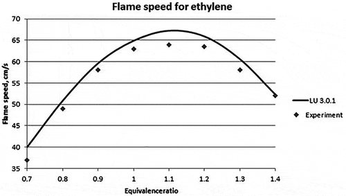
For validation in CHEMKIN, the temperature and pressure inside the reactor were set at 298 K and 1 atm, respectively. The equivalence ratioFootnote1 was varied between 0.6 and 1.5 for all the fuels. The model considered was flame speed calculation model. The results obtained for propene, methane, and ethylene fuels are given in , , and , respectively. The average absolute error in the flame speed calculation of propylene fuel for LU 3.0.1 mechanism is calculated to be 16.73% and for USC II 14.78% as compared with the experimental data. , , and show the graphical representation of the experimental and the new reduced mechanism for laminar flame speed along with the base mechanism (USC II) for propylene, methane, and ethylene, respectively.
Table 5. Laminar flame speed (cm/sec)—Comparison of simulation and experimental results for propylene (Davis and Law, Citation1998).
Table 6. Laminar flame speed—Comparison of simulation and experimental results for methane (Law et al., Citation2006).
Table 7. Laminar flame speed—Comparison of simulation and experimental results for ethylene (Jomaas et al., Citation2005).
Figure 2. Laminar flame speed for different equivalence ratios for propylene (Davis and Law, Citation1998).
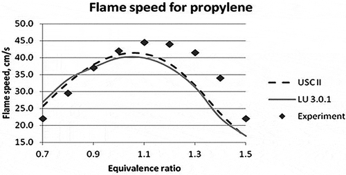
Figure 3. Laminar flame speed for different equivalence ratios for Methane (Vagelopoulos et al., Citation1994; Vagelopoulos and Egolfopoulos, Citation1998).
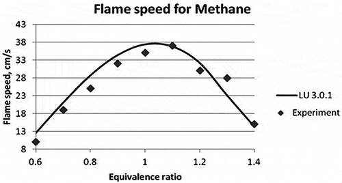
Figure 4. Laminar flame speed for different equivalence ratios for ethylene (Jomaas et al., Citation2005).
Ignition delay
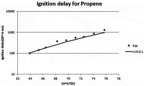
The ignition delay time can be defined as the period between the creation of a combustible mixture when the fuel is injected in an oxidizing environment and the sustained onset of the rapid reaction phase leading to the rise of temperature and pressure. Ignition delay was tested for propylene fuel. The reduced mechanism with 50 species was tested for ignition delay in CHEMKIN. This was compared with experimental data from Qin et al. (Citation2001). For validation in CHEMKIN, the pressure was taken as 4 atm, and the temperature was varied between 1200 and 1600 K. Fuel composition was C3H6/O2/Ar (3.17%/7.83%/89%). The model considered was a closed homogenous reactor. The results obtained are shown in . shows the graphical representation of the experimental and simulation results between Ignition delay time and 104/temperature for propylene air mixtures with the new mechanism.
Table 8. Ignition delay—Comparison of simulation and experimental results.
Figure 5. Ignition delay time for propylene (Qin et al., Citation2001).
Adiabatic flame temperature
The adiabatic flame temperature is a measure of the maximum temperature that could be reached by combusting a particular gas mixture under a specific set of conditions. In a real system, which includes heat losses and chemical kinetic and/or mass transport limitations, the flame temperature is likely to be lower than the adiabatic flame temperature.
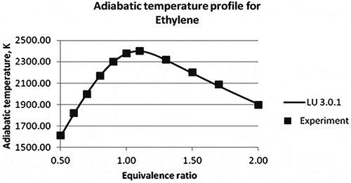
For estimating adiabatic flame temperatures, the equilibrium calculation model was used in CHEMKIN. The inlet composition of fuel and air mixtures was varied to obtain different equivalence ratios. The initial temperature and pressure were set at 300 K and 1 atm, respectively, for both methane and ethylene, and the estimated adiabatic temperature is 2000 K. The estimated adiabatic temperature for propylene is 2341 K at equivalence ratio Φ = 1, and the experimental value as determined by Davis et al. (Citation1999) is 2342 K.
The results from Law et al. (Citation2006) were considered to validate the mechanism for methane and ethylene adiabatic flame temperatures. Adiabatic flame temperature comparison of CHEMKIN simulation and experimental results for methane and ethylene flames at different equivalence ratios are shown in and , respectively. The equivalence ratio varies in the range of 0.5–2 for either of the cases. In both cases, the maximum adiabatic temperature was observed at the equivalence ratio of 1.0–1.1, i.e., towards the leaner side of the fuel. Average percentage errors of the different reduced mechanisms are compared with experimental data in .
Table 9. Average percentage error of the reduced mechanisms compared with experimental data.
Figure 6. Adiabatic flame temperature of methane (Law et al., Citation2006).
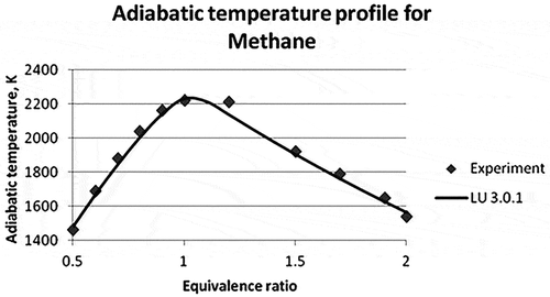
Figure 7. Adiabatic temperature profile of ethylene (Law et al., Citation2006).
Application of reduced mechanism LU 3.0.1 in CFD simulations
ANSYS Fluent can simulate the mixing and reaction of chemical species, including homogeneous and heterogeneous combustion models and surface deposition/reaction models. The Navier-Stokes equations and the equations for mass, energy, and species transport are to be solved in any model used. Two types of combustion/chemical reaction models: eddy dissipation concept, finite-rate (EDC) model and non-premixed probability density function (PDF) combustion model were used to model different air-assisted flares using the developed LU 3.0.1 mechanism in ANSYS Fluent.
Physical and turbulence models
In general, the flare flow is turbulent when the exit diameter is large and jet velocity is high. The flow can be predicted more accurately with the Reynolds number. Turbulent flows are characterized by high-frequency fluctuating velocity fields, which result in the Reynolds stresses. The turbulence boosts the mixing of transported quantities such as momentum, energy, and species concentration and affects the chemical reaction process. Therefore, a turbulence model is needed to simulate the flare with the chemical kinetics playing a dominative role in flare reactions. There are many turbulence models available in the commercial software package ANSYS Fluent. The standard k-ɛ model (Wilcox, Citation1998) is considered the most robust for a wide range of applications. One of the more successful recent developments is the realizable k-ɛ model. A new formulation for the turbulent viscosity and a transport equation for the dissipation rate, ɛ, that is derived from an exact equation for the transport of the mean-square vorticity fluctuation is included in the realizable k-ɛ model. Realizable k-ɛ shows a better ability to capture the mean flow (Shih et al., Citation1993).
Non-premixed combustion model
To run the cases in non-premixed combustion model, pre-PDF is created and it contains the required mean mixture fractions of each species involved in combustion. The PDF table is made up from a number of flamelets. These flamelets are embedded together to generate the PDF table. The fuel composition is given during the generation of flamelets. But in the EDC model, the species equations are solved for each species.
In non-premixed combustion, fuel and oxidizer enter the reaction zone in different streams, whereas in premixed combustion, reactants are mixed at the molecular level before burning. Once mixed, the chemistry can be treated as in a chemical equilibrium with the equilibrium model, with the steady laminar flamelet model (Peters, Citation1984), or significantly away from chemical equilibrium with the unsteady laminar flamelet model. A nonadiabatic steady-state laminar flamelet model is used for all the cases (Patki et al., Citation2014). At this point, CHEMKIN mechanism file is imported for generating flamelets. Flamelets are generated until either the maximum number of flamelets is reached or the flamelets are extinguished. Extinguished flamelets are not included in library. The parameters used for flamelet generation are listed in . These parameters are limited by computer memory.
Table 10. Flamelet generation parameters.
The grid refinement was used while generating the flamelets. ANSYS Fluent has the option for automated grid refinement of steady flamelets, where an adaptive algorithm inserts grid points so that the change of values, as well as the change of slopes, between successive grid points is less than user-specified tolerances. During automated grid refinement, a steady solution is calculated on a coarse grid with a user-specified initial number of grid points in flamelets. When it reaches the convergence, a new grid point is inserted between a point i and its neighbor (i + 1) if it satisfies the eq 1 below.
where is the value for each temperature and species mass fraction at grid point i, εv is a user-specified maximum change coefficient, and vmax and vmin are the maximum and minimum values over all grid points. The parameters for automated grid refinement are listed in .
Table 11. Grid refinement parameters for flamelet.
After the flamelets are generated, the flamelet profiles are convoluted with the assumed-shape PDFs as in eq 2 and then tabulated for look-up in ANSYS Fluent.
where f is the mixture fractions, χst is the scalar dissipation rate, and ϕ is the species mass fraction or temperature. The parameters used to generate the PDF table are listed in .
Table 12. Parameters used to generate the PDF table.
Before starting each case, the solution was initialized from the crosswind-flow inlet. An isosurface (z = 0) parallel to x-y plane was created at the center of domain. The maximum temperature at the z = 0 plane was monitored during iteration. Once the temperature was stabilized and the solution was converged, the results were saved for further analysis. The emission was measured at the top surface (outlet) of the domain.
PDF model settings were applied to six propylene-based cases of the 2010 TCEQ air-assisted flare study with the Moss-Brookes soot model. The k-ɛ turbulent model (realizable) with standard wall functions was used as viscous model. The SIMPLE (Semi-Implicit Method for Pressure Linked Equations) algorithm was enabled for pressure-velocity coupling.
Modeling soot and radiation
In the Moss-Brookes soot model, C2H2 and C6H6 are used as precursors along with the Fenimore-Jones oxidation model (Fenimore and Jones, Citation1967). In the current soot oxidation model, partial-equilibrium (OH) model and instantaneous (O2) model are used. Although there has been a long debate over the years about the selection of oxidizers for soot, recent studies have proven that for premixed and diffusion flames, the models indicate that soot oxidation by OH dominates over that by O2 (Guo et al., Citation2016). The forming of soot in a flame is essentially a chemically controlled phenomenon. Solid carbon is produced by the conversion of low-molecular-weight gases in just a few milliseconds. Thermodynamics alone cannot adequately describe soot formation phenomena; it is inherently a kinetically limited process, since soot is formed beyond regimes where it is thermodynamically stable relative to the oxides of carbon. Chemistry occurs during all phases of soot production: inception, surface growth, aging, and surface oxidation. The kinetics and mechanisms of soot oxidation have been studied for decades, and it was found that the primary soot oxidizers in the flame are OH radical and O2 along with a few other minor species such as O radical (Khosousi and Dworkin, Citation2015; Siegla, Citation2013). Recent studies have shown that the OH radical plays much more important role than O2 in soot oxidation (Lee et al., Citation2009; Guo et al., Citation2016). Discrete ordinate and P1 radiation models in ANSYS Fluent were tested separately to account for radiation losses in the flame. It was observed that the radiation heat loss due to soot formation was negligible and the difference in temperatures with and without a radiation model was less than 10 K.
Simulation of air-assisted flare tests using the PDF model
Geometry
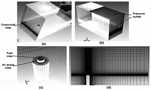
A three-dimensional geometry with rectangular domain is constructed in ANSYS Workbench design module. Its rectangular fluid domain and mesh structure is shown in . The geometry has the fuel inlet lifted slightly by 20 cm above the air-assist inlet. Slopped mesh for this geometry is created by using MultiZone and Edge sizing method in meshing module of ANSYS Workbench (ANSYS Inc., Citation2011). Crosswind inlet is on the left side of the geometry, and pressure outlet is given on the right-most and top right sides of the geometry. The total flow rate of each inlet in the simulation is matched to the actual test values. Mesh structure is made denser at stack inlet for better combustion analysis. Orthogonal quality of mesh is kept at 0.76, and grid size is around 0.8 million cells. The mesh is successfully checked for good skewness.
Comparison of PDF predictions with measured DRE/CE data
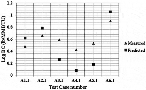
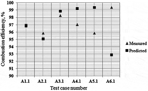
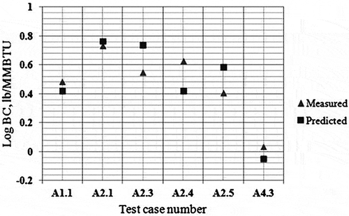
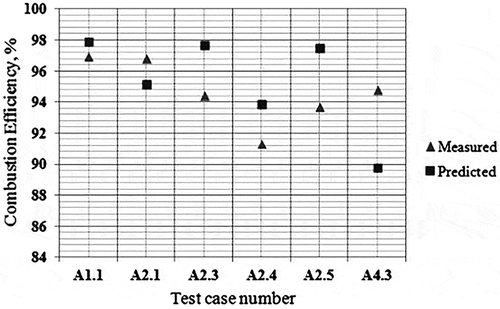
shows computational domain and the mesh view of the geometry used in the simulations. Carbon balance error for these preliminary simulations for current PDF model has been checked. Initial results for the soot are given in , whereas the CE results for these tests are shown in . It was observed that soot yields can be predicted within a factor of 2.23 (with an average of 1.78) whereas CEs are predicted within 6.54% (with an average of 2.30%) with the LU 3.0.1 mechanism for the air-assisted flare cases in 2010 TCEQ Flare Study.
Eddy dissipation concept (EDC) model
The turbulence-chemistry interaction EDC model incorporates detailed chemical mechanisms while modeling reacting turbulent flows (Magnussen and Hjertager, Citation1981). It is rigorous and hence is computationally expensive. The EDC model assumes that the reactions in the flame are occurring in small turbulent structures, called fine scales. In general, the reactions taking place in the flame are governed by the Arrhenius rates. These reaction rates are then integrated numerically using ISAT (in situ adaptive tabulation) algorithm. Using the ISAT algorithm thus reduces the computational time for solving the detailed reaction kinetics. This model has been successfully used by the same group in recent past (Singh et al., Citation2012, Citation2014). The general findings with remarks of EDC versus PDF model are shown in .
Table 13. Comparison of EDC and PDF models.
In this study, in the EDC model, the chemistry was updated after each iteration. To reduce computational time, ISAT algorithm was enabled. The cases run using EDC approach were completed in two stages. Initially “cold flow,” where the combustion chemistry was disabled, was simulated. Once a converged cold flow was obtained, the region near the flare stack was patched with a high temperature of 2000 K as a source of ignition. The EDC chemistry modeling was then enabled and then the combustion of the fuel started, which further raised the plume temperature.
Simulation of air-assisted flare tests using the EDC model
Geometry
The geometry was built in GAMBIT previously (Singh et al., Citation2012), and the same was used for the EDC simulation of air-assist cases in conjunction with the reduced mechanism LU 3.0.1. The length, width, and height of the geometry were kept as 30 m, 10 m, and 30 m, respectively. The flare was located at 5 m from the left side and at the center of the width.
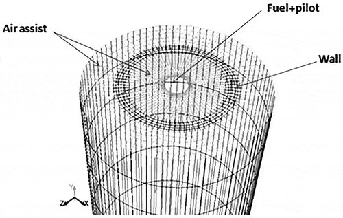
The configuration provided enough time for the flame chemistry to be completed inside the domain. The height of the flare stack was kept as 10 m and the diameter as 1.05 m. The geometry was simplified by modifying the fuel jet inlet. Simpler ring-shaped geometry was built, as shown in . The pilot mixed with the jet stream was given from the centermost surface. The ring was defined as a wall that divided the two air-assist inlets. The rest of the circular area acted as source for the air assist. The crosswind flows were from the left to the right side of the domain. The largest velocity and species concentration gradients were located in regions near the stack. To increase the accuracy of the reacting flow profile, the mesh density near the stack was kept higher relative to other zones in the domain. The grid had 842,390 cells and was successfully checked for skewness.
Comparison of EDC predictions with measured DRE/CE data
and show the comparisons of predictions by the CFD simulations using EDC model for CE () and soot () with analytical results generated from field sampling during the Comprehensive Flare Study Project at the John Zink facility, Tulsa, Oklahoma (UT, Texas 2011). It was observed that soot yields can be predicted within a factor of 1.35 on an average whereas CEs are predicted within 3.04% average error with the LU 3.0.1.
Conclusion
A reduced reaction mechanism capable of predicting both soot and VOC species was developed and validated successfully against literature data. LU 3.0.1 performs better in the case of ignition delay and adiabatic flame temperature as compared with the LU 1.0 and LU 1.1 mechanisms. In the case of laminar flame speed, performance of LU 3.0.1 is comparable to the full USC II mechanism. Overall, the results show that the simulation and experimental literature data are in good agreement for light hydrocarbons.
The LU 3.0.1 mechanism was further tested for the prediction of soot. It was used in conjunction with the CFD model to describe turbulence-chemistry interaction to simulate TCEQ 2010 air-assisted flare tests. CFD simulation results are in good agreement with the experimental data when used in conjunction with the non-premixed PDF model and EDC models. For high-LHV/high-flow flares, non-premixed combustion model can be used to predict CE and soot yield but cannot predict any VOC emissions. CE predictions from the EDC model are comparable to those from PDF but often difficult to arrive at converged solutions. A comparison between PDF and EDC models is presented in . Further simplification of this combustion mechanism can be pursued for application in conjunction with more complex turbulence models such as the large eddy simulation (LES) model in the future.
Table 14. Comparison of PDF and EDC model predictions.
Supplemental_Info.docx
Download MS Word (375 KB)Funding
Financial support from Texas Commission on Environmental Quality (TCEQ) Grant for Activities Program (project no. 582-10-94307-FY14-06), TCEQ Supplemental Environmental Program (SEP Agreement No. 2009-009), and the Texas Air Research Center (TARC grant 079LUB0096A) are gratefully acknowledged.
Supplemental data
Supplemental data for this article can be accessed on the publisher’s website.
Additional information
Funding
Notes on contributors
Vijaya Damodara
Vijaya Damodara is a graduate research student of chemical engineering at Lamar University, Beaumont, TX.
Daniel H. Chen
Daniel H. Chen and Helen H. Lou are professors in the Department of Chemical Engineering at Lamar University, Beaumont, TX.
Kader M.A. Rasel
Kader M.A. Rasel is a graduate research student of chemical engineering at Lamar University, Beaumont, TX.
Peyton Richmond
Peyton Richmond is a professor in the Department of Chemical Engineering at Lamar University, Beaumont, TX.
Anan Wang
Anan Wang is a graduate research student of chemical engineering at Lamar University, Beaumont, TX.
Xianchang Li
Xianchang Li is a professor in the Department of Mechanical Engineering at Lamar University, Beaumont, TX.
Notes
1 Many properties of combustion processes strongly depend on the stoichiometry of the combustion mixture. Equivalence ratio is defined as the ratio of the actual fuel/oxidizer ratio to the fuel/oxidizer ratio in the stoichiometric equation. Equivalence ratio is the most frequently used parameter to describe the stoichiometry of a mixture.
References
- Aboje, A.A., K.J. Hughes, D.B. Ingham, L. Ma, A. Williams, and M. Pourkashanian. 2015. Numerical study of a wake-stabilized propane flame in a cross-flow of air. J. Energy Inst. 90(1):145–158. doi:10.1016/j.joei.2015.09.002
- Allen, D.T., and V.M. Torres. 2011. TCEQ 2010 Flare Study Final Report—Appendices. August 1, 2011. http://www.tceq.texas.gov/assets/public/implementation/air/rules/Flare/2010flarestudy/2010-flare-study-final-appendices.pdf ( accessed January 24, 2017).
- ANSYS Inc. 2011. ANSYS FLUENT user guide, release 14.0. Canonsburg, PA: ANSYS Inc.
- Blanquart, G. 2008. Chemical and statistical soot modeling. Ph.D. dissertation, Stanford University, Stanford, CA.
- Bowman, B.R., D.T. Pratt, and C.T. Crowe. 1973. Effects of turbulent mixing and chemical kinetics on nitric oxide production in a jet-stirred reactor. Proc. Combust. Inst. 14:819–830.
- Busupally, M.R., and A. De. 2016. Numerical modeling of soot formation in a turbulent C2H4/air diffusion flame. Int. J. Spray Combust. Dyn. doi: 10.1177/1756827716638814.
- Colket, M.B., R.J. Hall, J.J. Sangiovanni, and D.J. Seery. 1989. The Determination of Rate-Limiting Steps during Soot Formation. UTRC89-13. Hartford CT: United Technologies Research Center East.
- Davis, S.G., and C.K. Law. 1998. Determination of and fuel structure effects on laminar flame speeds of C1 to C8 hydrocarbons. Combust. Sci. Technol. 140:427–449. doi:10.1080/00102209808915781
- Davis, S.G., K. Law, and H. Wang. 1999. Propene pyrolysis and oxidation kinetics in a flow reactor and laminar flames. Combust. Flame 119:375–399. doi:10.1016/S0010-2180(99)00070-X
- Fenimore, C.P., and G.W. Jones. 1967. Oxidation of soot by hydroxyl radicals. J. Phys. Chem. 71:593–597. doi:10.1021/j100862a021
- Fortner, E.C., W.A. Brooks, T.B. Onasch, M.R. Canagaratna, P. Massoli, J.T. Jayne, J.P. Franklin, W.B. Knighton, J. Wormhoudt, D.R. Worsnop, C.E. Kolb, and S.C. Herndon. 2012. Particulate emissions measured during the TCEQ Comprehensive Flare Emission Study. Ind. Eng. Chem. Res. 51:12586–12592. doi:10.1021/ie202692y
- Frenklach, M. 2002. Reaction mechanism of soot formation in flames. Phys. Chem. Chem. Phys. 4:2028–2037. doi:10.1039/b110045a
- Glarborg, P., R.J. Kee, J.F. Grcar, and J.A. Miller. 1986. PSR: A Fortran Program for Modeling Well Stirred Reactors. Technical report SAND86-8209. Albuquerque, NM: Sandia National Laboratories.
- Guo, H., P.M. Anderson, and P.B. Sunderland. 2016. Optimized rate expressions for soot oxidation by OH and O2. Fuel 172:248–252. doi:10.1016/j.fuel.2016.01.030
- Hautman, D.J., F.L. Dryer, K.P. Schug, and I. Glassman. 1981. A multiple-step overall kinetic mechanism for the oxidation of hydrocarbons. Combustion Science and Technology 25(5–6):219–235.
- Huang, R.F., and J.M. Chang. 1994. The stability and visualized flame and flow structures of a combusting jet in cross flow. Combustion and Flame 98(3):267–278.
- Huang, R.F., and M.J. Yang. 1996. Thermal and concentration fields of burner-attached jet flames in cross flow. Combustion and Flame 105(1):211–224.
- Jomaas, G., X.L. Zheng, D.L. Zhu, and C.K. Law. 2005. Experimental determination of counterflow ignition temperatures and laminar flame speeds of C2–C3 hydrocarbons at atmospheric and elevated pressures. Proc. Combust. Inst. 30(1):193–200.. doi:10.1016/j.proci.2004.08.228
- Khosousi, A., and S.B. Dworkin. 2015. Detailed modeling of soot oxidation by O2 and OH in laminar diffusion flames. Proc. Combust. Inst. 35:1903–1910. doi:10.1016/j.proci.2014.05.152
- Kindzierski, W.B. 1999. Importance of human environmental exposure to hazardous air pollutants from gas flares. Environ. Rev. 8:41–62. doi:10.1139/a00-005
- Kronenburg, A., R.W. Bilger, and J.H. Kent. 2000. Modeling soot formation in turbulent methane–air jet diffusion flames. Combust. Flame 121:24–40. doi:10.1016/S0010-2180(99)00146-7
- Law, C.K., A. Makino, and T.F.Lu. 2006. On the off-stoichiometric peaking of adiabatic flame temperature with equivalence ratio. Combust. Flame 145:808–819.doi:10.1016/j.combustflame.2006.01.009
- Lawal, M.S., M. Fairweather, P. Gogolek, D.B. Ingham, L. Ma, M. Pourkashanian, and A. Williams. 2013. CFD predictions of wake-stabilised jet flames in a cross-flow. Energy 53:259–269. doi:10.1016/j.energy.2013.02.020
- Lawal, M.S., M. Fairweather, D.B. Ingham, L. Ma, M. Pourkashanian, and A. Williams. 2010. Numerical study of emission characteristics of a jet flame in cross-flow. Combust. Sci. Technol. 182:1491–1510. doi:10.1080/00102202.2010.496379
- Lee, S.Y., S.R. Turns, and R.J. Santoro. 2009. Measurements of soot, OH, and PAH concentrations in turbulent ethylene/air jet flames. Combust. Flame 156:2264–2275. doi:10.1016/j.combustflame.2009.09.005
- Lou, H.H., Chen, D., C.B. Martin, X.C. Li, K.Y. Li, H. Vaid, K.D. Singh, and Gangadharan, P. 2012. Optimal reduction of the C1–C3 combustion mechanism for the simulation of flaring. Ind. Eng. Chem. Res. 51(39): 12697–12705. doi:10.1021/ie2027684
- Lou, H.H., C.B. Martin, D. Chen, X.C. Li, K.Y. Li, H. Vaid, A.T. Kumar, and K.D. Singh, D.P. Bean Jr. 2011. A reduced reaction mechanism for the simulation in ethylene flare combustion. Clean Technol. Environ. Policy 14(2):229–239. doi:10.1007/s10098-011-0394-9
- Lou, H.H., C.B. Martin, D. Chen, X.C. Li, K.Y. Li, H. Vaid, A. Tula, and K.D. Singh. 2012. Validation of a reduced combustion mechanism for light hydrocarbons. Clean Technol. Environ. Policy 14(4):737–748. doi:10.1007/s10098-011-0441-6
- Lu, T., and C.K. Law. 2005. A directed relation graph method for mechanism reduction. Proceedings of the Combustion Institute 30(1):1333–1341.
- Magnussen, B.F., and B.W. Hjertager. 1981. On the structure of turbulence and a generalized eddy dissipation concept for chemical reaction in turbulent flow. In 19th AIAA Aerospace Meeting, St. Louis, MO. http://folk.ntnu.no/ivarse/edc/EDC1981.pdf (accessed March 20, 2017).
- McEnally C.S., L.D. Pfefferle, B. Atakan, and K. Kohse-Höinghaus. 2006. Studies of aromatic hydrocarbon formation mechanisms in flames: Progress towards closing the fuel gap. Prog. Energy Combust. Sci. 32:247–294. doi:10.1016/j.pecs.2005.11.003
- McEwen, J.D., and M.R. Johnson. 2012. Black carbon particulate matter emission factors for buoyancy-driven associated gas flares. J. Air Waste Manage. Assoc. 62:307–321. doi:10.1080/10473289.2011.650040
- Melius, C.F., M.E. Colvin, N.M. Marinov, W.J. Pitz, and Senkan, S. M. 1996. Definitive studies of key combustion processes—Mechanisms of Soot formation: The propargyl + allyl system. Proc. Combust. Inst. 26(1):685–692.
- Miller, J.A., M.C. Branch, W.J. McLean, D.W. Chandler, M.D. Smooke, and R.J. Kee. 1985. The conversion of HCN to NO and N2 in H2– O2– HCN– Ar flames at low pressure. In Symposium (International) on Combustion, 20(1):673–684. Pittsburgh, PA: The Combustion Institute.
- Miller, J.A., R.E. Mitchell, M.D. Smooke, and R.J. Kee. 1982. Toward a comprehensive chemical kinetic mechanism for the oxidation of acetylene: Comparison of model predictions with results from flame and shock tube experiments. In Symposium (International) on Combustion, 19(1):181–196. Pittsburgh, PA: The Combustion Institute.
- Peters, N. 1984. Laminar diffusion flamelet models in non-premixed turbulent combustion. Prog. Energy Combust. Sci. 10:319–339. doi:10.1016/0360-1285(84)90114-X
- Pohl, J.H. 1984. Evaluation of the Efficiency of Industrial Flares. EPA600-2-85-95. Washington, DC: U.S. Environmental Protection Agency.
- Pohl, J.H. 1985. Evaluation of the efficiency of industrial flares. EPA600-2-85-106. Washington, DC: U.S. Environmental Protection Agency.
- Pohl, J., and N. Soelberg. 1986. Evaluation of the efficiency of industrial flares: H2S gas mixtures and pilot assisted flares. EPA/600/2-86/080 (NTIS PB87102372). Washington, DC: U.S. Environmental Protection Agency.
- Patki, A., X. Li, D. Chen, H. Lou, P. Richmond, V. Damodara, L. Liu, K. Rasel, A. Alphones, and J. Zhou. 2014. Numerical simulation of black carbon (soot) emissions from non-premixed flames. J. Geosci. Environ. Prot. 2:15–24. doi:10.4236/gep.2014.24003
- Qin, Z., H. Yang, and C. Gardiner. 2001. Measurement and modeling of shock-tube ignition delay for propene. Combust Flame 124:246–254. doi:10.1016/S0010-2180(00)00200-5
- Reaction Design. 2013. CHEMKIN-PRO, version 15131. San Diego, CA: Reaction Design.
- Shih, T.H., J. Zhu, and J.L. Lumley. 1993. A realizable Reynolds stress algebraic equation model. NASA TM-105993.
- Siegla, D. 2013. Particulate Carbon: Formation during Combustion. New York: Springer Science and Business Media.
- Singh, K., T. Dabade, H. Vaid, P. Gangadharan, D. Chen, H.Lou, K. Li, X. Li, and C. Martin. 2012. Computational fluid dynamics modeling of industrial flares operated in a stand-by mode. Ind. Eng. Chem. Res. 51:12611–12620. doi:10.1021/ie300639f
- Singh, K., P. Gangadharan, D. Chen, H. Lou, X. Li, and P. Richmond. 2014. Parametric study of ethylene flare operations and validation of a reduced combustion mechanism. Eng. Appl. Comput. Fluid Mech. 8:211–228.
- Slavinskaya, N.A., and P. Frank. 2009. A modelling study of aromatic soot precursors formation in laminar methane and ethene flames. Combust. Flame 156(9):1705–1722. doi:10.1016/j.combustflame.2009.04.013
- Smith, G.P., D.M. Golden, M. Frenklach, N.W. Moriarty, B. Eiteneer, M. Goldenberg, and V.V. Lissianski. 2011. GRI-Mech 3.0, 1999. http://www.me.berkeley.edu/gri_mech (accessed January 24, 2017).
- Strosher, M.T. 1996. Investigations of flare gas emissions in Alberta; Report to Environment Canada, the Energy and Utilities Board, and the Canadian Association of Petroleum Producers. Edmonton, Alberta: EUB.
- Strosher, M.T. 2000. Characterization of emissions from diffusion flare systems. J. Air Waste Manage. Assoc. 50:1723–1733. doi:10.1080/10473289.2000.10464218
- Texas Commission on Environmental Quality. 2011. 2010 Flare Study—Particulate Appendix. Aerodyne Research Mobile Laboratory Particulate Measurements. http://www.Tceq.Texas.Gov/Assets/Public/Implementation/Air/Rules/Flare/2010flarestudy/2010-Flare-Study-Final-Appendices-Particulates.Pdf ( accessed August 14, 2012).
- Thomas, R., J. Smith, M. Jones, J. MacKay, and J. Jarvie. 2008. Emissions Modeling of Specific Highly Reactive Volatile Organic Compounds (HRVOC) in the Houston-Galveston-Brazoria Ozone Nonattainment Area. Austin, TX: Texas Commission on Environmental Quality.
- Torres, V.M., S. Herndon, Z. Kodesh, and D.T. Allen. 2012. Industrial flare performance at low flow conditions. 1. Study overview. Ind. Eng. Chem. Res. 51:12559–12568. doi:10.1021/ie202674t
- U.S. Environmental Protection Agency. 1991. 40 CFR Ch. I (7-1-09 Edition), Pt. 60, App. A-4, Method 9: Visual Determination of the Opacity of Emissions from Stationary Sources. http://www.deq.state.or.us/aq/forms/sourcetest/appendix_a1.pdf (accessed January 24, 2017).
- U.S. Environmental Protection Agency, Office of Air Quality Planning and Standards (OAQPS). 2012. Parameters for Properly Designed and Operated Flares, Report for Flare Review Panel. https://www3.epa.gov/airtoxics/flare/2012flaretechreport.pdf (accessed March 20, 2017).
- Vagelopoulos, C.M., and F.N. Egolfopoulos. 1998. Direct experimental determination of laminar flame speeds. In Twenty-Seventh Symposium (International) on Combustion, 513–519. Pittsburgh, PA: The Combustion Institute.
- Vagelopoulos, C.M., F.N. Egolfopoulos, and C.K. Law. 1994. Further considerations on the determination of laminar flame speeds with the counterflow twin flame technique. Proc. Combust. Inst. 25:1341–1347. doi:10.1016/S0082-0784(06)80776-9
- Wang, H., X. You, A.V. Joshi, S.G. Davis, A. Laskin, F. Egolfopoulos, and C.K. Law. 2007. USC Mech Version II. High-Temperature Combustion Reaction Model of H2/CO/C1-C4 Compounds. http://ignis.usc.edu/USC_Mech_II.htm (accessed January 24, 2017).
- Wilcox, D.C. 1998. Turbulence Modeling for CFD, Vol. 2, 103–217. La Cañada Flintridge, CA: DCW Industries.

