ABSTRACT
Significant amounts of volatile organic compounds and greenhouse gases are generated from wastewater lagoons and tailings ponds in Alberta, Canada. Accurate measurements of these air pollutants and greenhouse gases are needed to support management and regulatory decisions. A mobile platform was developed to measure air emissions from tailings pond in the oil sands region of Alberta. The mobile platform was tested in 2015 in a municipal wastewater treatment lagoon. With a flux chamber and a CO2/CH4 sensor on board, the mobile platform was able to measure CO2 and CH4 emissions over two days at two different locations in the pond. Flux emission rates of CO2 and CH4 that were measured over the study period suggest the presence of aerobic and anaerobic zones in the wastewater treatment lagoon. The study demonstrated the capabilities of the mobile platform in measuring fugitive air emissions and identified the potential for the applications in air and water quality monitoring programs.
Implications: The Mobile Platform demonstrated in this study has the ability to measure greenhouse gas (GHG) emissions from fugitive sources such as municipal wastewater lagoons. This technology can be used to measure emission fluxes from tailings ponds with better detection of spatial and temporal variations of fugitive emissions. Additional air and water sampling equipment could be added to the mobile platform for a broad range of air and water quality studies in the oil sands region of Alberta.
Introduction
Wastewater, tailings ponds, and lagoons are significant sources of volatile organic compounds (VOC) and greenhouse gases (GHG). In Alberta, Canada, the exploration of oil sands generates significant amount of tails stored in tailings ponds that cover 176 km2 (Allen, Citation2008). Fugitive air emission of VOC and GHG from these tailings ponds occurs due to evaporation and chemical/biological activities (Bordenave et al., Citation2010; Penner and Foght, Citation2010; Siddique et al., Citation2011, Citation2012; Yeh et al., Citation2010). Typical lagoons in municipal waste management centers produce CO2 and CH4 through aerobic, anaerobic, and facultative bacterial decomposition processes (Hamilton et al., Citation2006; Sharpe and Harper, Citation1999). It is estimated that 46% of Alberta’s CH4 emissions are from fugitive emission sources involving leaks and large area sources. The present Climate Leadership Plan by the Government of Alberta puts a cap on oil-sands-related GHG emission of 100 MT/year, with an aim of 45% overall reduction of CH4 emission from the 2014 levels by 2025 (Climate Leadership Plan: Government of Alberta, Citation2016).
Gas emission from an oil sands tailings pond is spatially heterogeneous, with different zones, such as the tailings outfalls, bitumen slicks, oil films, and mature fine tailings, emitting at different rates, which makes the estimation of overall emission rate a challenging task. In 2014 Alberta Environment and Sustainable Resource Development (AESRD, Citation2014) established a directive titled “Quantification for Area Fugitive Emissions at Oil Sands Mines,” which required annual monitoring of CH4 and CO2 emissions from tailings ponds and mine face surfaces for reporting under the “Specified Gas Emitters Regulation and Specified Gas Reporting Regulation (Section 3.2)” (Alberta Regulation, Citation2004, Citation2007). One of the minimum requirements set by the directive for tailings ponds fugitive GHG sampling is that sampling needs to be conducted in each zone at three locations or at one location per 400,00 m2 (40 ha), whichever is greater (AESRD directive version 2.0, Citation2014). Therefore, measurement techniques taking both spatial and temporal variability of emission fluxes into consideration are required.
As one of the most common techniques for emission measurement, flux chambers have been used in most tailings emission surveys. However, traditional fixed flux chamber measurements have the disadvantage of lack of spatial and temporal representativeness. On the other hand, mobile platforms can carry environmental monitoring equipment to cover a large surface area where the emissions are occurring with less labor requirement, especially for remote areas without power supply or other necessary infrastructure. Municipal wastewater treatment facilities have similar issues and challenges for measuring air emissions from the lagoons. To facilitate the development of new emission measurement methods, an autonomous mobile platform (Mobile Platform) was developed to measure air emissions from tailings ponds and wastewater lagoons. The unit was tested in the fall of 2015 at a municipal wastewater lagoon and measurements were taken for CO2 and CH4 emission fluxes. This paper presents the testing results and recommends future applications of this technology.
Mobile platform instrumentation
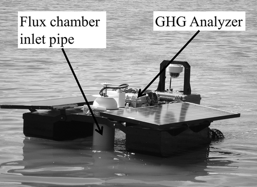
The Mobile Platform was designed for autonomous operation in tailings ponds and lakes. The unit is powered by an on-board battery and two solar panels in order to avoid cross contamination from the exhaust of internal combustion engines. During a typical sunny day, the electric power is enough to power the Mobile Platform for up to 10 hr of continuous operation. The Mobile Platform can be programed to collect air samples at predetermined locations using an on-board computer and a global positioning system (GPS) sensor. It is equipped with a flux chamber and a continuous CO2/CH4/H2O gas analyzer (GHG analyzer). The unit has four key aspects in its design: structural stability and robustness; power management; navigation and communication; and sensor operation and control.
Structural stability and robustness
Two main hulls carry the weight of the Mobile Platform on water. Buoyancy of the hulls is designed for proper level of float of the structure. A motor is attached on the rear end of each hull. The two hulls are connected through a platform base. A third smaller hull is used for holding a battery, an on-board computer, and control hardware. The platform base has a space of 3 × 2 feet for holding sensors and flux chamber. The hulls are connected through hinges for allowing freedom of movement of the Mobile Platform in the presence of moderate tides in water. With a typical payload of slightly above 100 kg, the platform base is about 1 foot above the water surface. shows the structural features of the Mobile Platform.
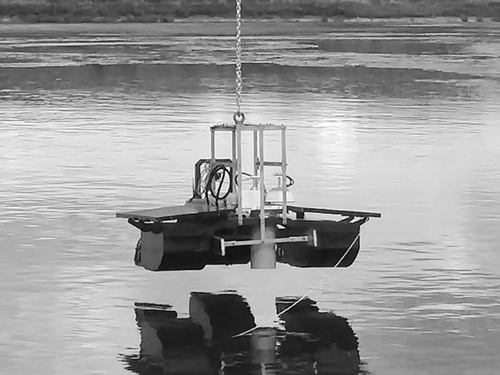
To launch the Mobile Platform into a pond or a lagoon safely where there are topographical restrictions or environmental hazards, an additional metal support frame was designed. The removable metal frame provides the option of launching the Mobile Platform onto a pond surface without the operator’s exposure to the contaminated water. The framing can also ensure structural robustness during shipments and handlings. The metal frame, consisting of 30 individual pieces, can be assembled on the existing Mobile Platform on a short notice. The framing reinforces the overall structure by spreading the load distribution in case of vertical lifting of the Mobile Platform. Center of gravity, stresses on the joints, axis and freedom of movements, and so on were carefully addressed in the framing design. shows launching of the Mobile Platform into a wastewater lagoon.
Power management
The Mobile Platform is powered by two solar panels and a 75-AH battery bank. A fully charged battery and the solar panels can run the unit for up to 10 hr continuously on a typical sunny day. The battery power supply in the absence of solar radiation lasts up to 6 hr. Arrangements were made for power supply for the GHG analyzer and a flux chamber from the battery supply bus. The power management system consists of charging units, current sensors, power control switches, and power management computation unit. Power management and hardware control are run by an embedded computer and a processing unit in a waterproof instrument suitcase.
Navigation and communication
The unit can be navigated through an on-board control system involving 20-A motor drives, two DC motors, a GPS (Garmin 18 × 5Hz), and navigation software (custom built). Communication to the unit is enabled through a cellular 4G data link and a backup WiFi communication. The WiFi has a range of 100 m, and the cellular link allows remote access to the Mobile Platform from anywhere provided that a cellular network is available at the deployment site. Measurements can be carried out while the Mobile Platform is in motion. However, better accuracy in measurement is achieved under static conditions.
Sensor operation and control
A GHG analyzer (Los Gatos Research, Ultraportable GGA 915-0011) is installed on the platform base of the mobile unit. A flux chamber (LICOR model 8100-104) is mounted on the platform base to sample air from the water surface. For this study the flux chamber is set to close for 2 min and open for 28 min in every sampling cycle (30 min in total) for day 1, and 5 min closed and 15 min open for day 2. This is to test the capabilities of the chamber/platform for various sample cycles. During the time interval when the chamber is closed, the CO2 and CH4 concentrations are continuously measured with the GHG analyzer in a closed loop. An 8-inch (200-mm) diameter polyvinyl chloride (PVC) pipe was mounted through a hole on the platform base (see ). The PVC pipe was sealed in one end with the flux chamber. The height of the pipe was adjusted with the floating level of the Mobile Platform so that the lower end of the pipe is submerged in water while the unit is floating. The height of the pipe above water level for present measurements is 12 inches (300 mm). Measurement cycles of the analyzer-flux chamber (closed/open durations) can be controlled through the on-board computer. Complete system integrity involving the analyzer, flux chamber, and collection pipe functionalities was tested with a release of CO2 under the water surface in a laboratory environment. The GHG analyzer was calibrated using certified reference gases in a chemistry laboratory. The manufacturer-provided measurement uncertainties in CH4, CO2, and H2O are less than 2 ppb, 300 ppb, and 100 ppm, respectively. Water vapor effect is considered in measurements.
Site selection
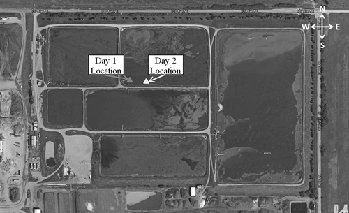
The study was carried out in a biosolids lagoon of the City of Edmonton Waste Management Centre, situated to the northeast of Edmonton (City of Edmonton, Citationn.d.). Biosolids, which contain nutrient-rich organic matter, are a by-product of domestic wastewater treatment. The biosolids lagoon has been shown to be an emission source of CH4 and CO2 (Brown et al., Citation2010; Mahzbain, Citation2012; Majumder et al., Citation2014; EPA, Citation2015). Meteorological data were collected from an Ambient Monitoring Station of Alberta Environment and Parks (Alberta Environment and Parks, Citationn.d.).
Results and discussion
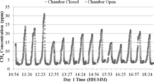
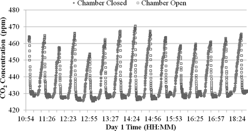
Measurements were carried out at two locations in the lagoon as shown in during daytime for 2 days. Measurements were taken under static conditions (i.e., no movement of the mobile platform). On day 1, measured CH4 concentrations inside the flux chamber gradually increased from a level of 2.5 ppm to a range of 32.6 ppm () during the 2-min measurement cycles (chamber closed). Correspondingly, the measured concentrations of CO2 were between 425 ppm and 467.5 ppm (). During the postmeasurement (chamber open) period, the CH4 and CO2 concentrations gradually dropped to the surface ambient levels and stayed relatively constant for the duration (2.5 and 425 ppm, respectively). Slightly elevated CH4 concentration over the lagoon was observed compared to the reported value of 2.1 ppm at the nearest ambient air monitoring station about 4 km sourthwest of the lagoon. Data for background CO2 levels were not available from the ambient air monitoring station. Concentration profiles in – show that the sensor and flux chamber were working properly before each measurement cycle.
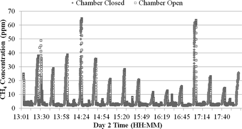
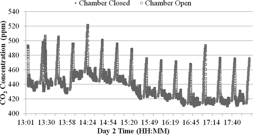
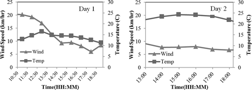
and show the time series of CH4 and CO2 concentrations on day 2. Measured CH4 concentrations ranged from 2.1 ppm to 63.9 ppm during the 5-min flux measurement cycles. For CO2, the concentration spanned from 412.9 ppm to 518.0 ppm. During the postmeasurement (chamber open) period, CH4 concentrations gradually dropped to the surface ambient level as on day 1. However, ambient baseline CO2 concentration level at the lagoon varied in the range of 420–460 ppm. The apparent variation in CO2 concentration profile on day 2 can be explained by the meteorological data provided in . The lower wind speed results in limited dispersion and supports the accumulation of CO2 over the lagoon surface in this case. No sign of CH4 accumulation (being a lighter compound) over the lagoon surface was observed on day 1 or day 2, irrespective of the variations in temperature and wind speed.
Flux values were calculated from concentration profiles using the following equation:
where is the flux;
is the concentration measured at the end of the measurement cycle at time
;
is the concentration measured after the chamber was closed at time
;
is the total enclosed volume of the system; and
is the area covered by the pipe. For flux calculations in all measurement cycles,
was chosen at 20 sec later than the chamber close control signal and
was determined accordingly. This is based on the considerations regarding the mechanical movement of the flux chamber, proper seal, and the overall stability of the measurement system.
Uncertainty of flux measurements was estimated using Monte Carlo simulation based on inaccuracies in measurements of concentration, sampling time, and chamber volume. The calculated uncertainty of the fluxes is about 5%.
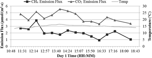
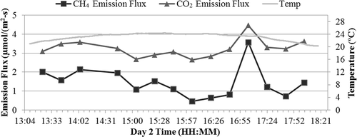
Average CH4 emission flux was 2.18 µmol/(m2-sec) and 1.48 µmol/(m2-sec) for day 1 and day 2, respectively. For CO2 emission flux, the average was 4.32 µmol/(m2-sec) and 3.22 µmol/(m2-sec) for day 1 and day 2, respectively ( and and ). These emissions fluxes are of the same order of magnitude as determined using eddy covariance technique at a similar lagoon (30-min average data over 3 months in summer 2013) (Zhang et al., Citation2014). It is apparent that stronger wind speed on day 1 corresponds to higher emission fluxes of CH4 and CO2 from the lagoon as compared to day 2. Spikes in emission fluxes for both CH4 and CO2 were observed at 5:04 p.m. on day 2. This could be a localized effect caused by a bubble released under the sampling location. The enhanced spikes correlate with the observed concentration profiles for day 2 in and , respectively. No measurements were done at night times due to the limited battery power supply.
Table 1. Summary of CH4 and CO2 emission fluxes on day 1 and day 2.
We believe that both aerobic and anaerobic processes are contributing toward emissions in the wastewater treatment lagoon. This is apparent from data in , where CO2 fluxes are found to be consistently higher than CH4 on both days. It should be noted that the differences in the CH4 and CO2 emission fluxes are well above the measurement uncertainty estimates. Anaerobic digestion is an established technology for the treatment of wastes and wastewater. Studies showed that the final product is a mixture of methane (55–75 vol%) and carbon dioxide (25–45 vol%) that can be used for heating, upgrading of natural gas quality, or cogeneration of electricity and heat (Reith et al., Citation2003). Being closer to the surface, the upper part of the lagoon water would contribute more to the aerobic process, whereas the deeper part is expected to contribute more to the anaerobic processes. Contributions of aerobic/anaerobic processes are dependent on the dynamic balance of wind, temperature, and the lagoon water conditions. To use a conservative assumption that equal amounts of CH4 and CO2 are generated by anaerobic processes, the relative contributions of aerobic CO2 can be calculated from differences in mean values of CO2 fluxes and the corresponding CH4 for day 1 and day 2. The results are given in . It is interesting to note that the ratio of aerobic/anaerobic contributions remains similar in different environment conditions of the two days of measurements.
Table 2. Relative contribution of aerobic and anaerobic zones in the lagoon.
This study demonstrated the fugitive air emission measurement capabilities of the mobile platform. Future applications will include the deployment of the platform over oil sands tailings ponds for fugitive air emission monitoring. Additionally, water sampling equipment could be installed on the platform to collect spatially representative samples for water chemistry studies. The platform will also be deployed in municipal wastewater lagoons and small lakes in Alberta for air and water quality studies.
Conclusion
A Mobile Platform was designed and developed for tailings pond air emissions monitoring. A flux chamber and GHG sensors were successfully integrated with the on-board computer and data system of the Mobile Platform. The Mobile Platform was tested at a municipal wastewater treatment lagoon. CH4 and CO2 concentrations were measured with the on-board sensors with varying sampling cycles. The data were used to generate CH4 and CO2 emission fluxes. The emission fluxes measured in this study are within the same order of magnitude as the emission fluxes measured by eddy covariance technique at a similar location. Differences in ratios of CH4 and CO2 emission fluxes indicate the presence of aerobic and anaerobic zones in the lagoon. This Mobile Platform will enable the environmental agencies to study biogenic GHG emissions from water bodies and also fugitive emissions from area sources such as the tailings ponds and wastewater treatment lagoons. This platform can also be used for a wide range of integrated air and water studies.
Acknowledgment
The authors thank Allan Mumby of EPCOR Water Services, Inc., for his support in coordinating site preparation and access.
Additional information
Notes on contributors
Long Fu
Long Fu, Ph.D., is the Director of Standards, Quality and Innovation with Alberta Environment and Parks.
Quamrul Huda, Ph.D., is a remote sensing scientist with Alberta Environment and Parks.
Zheng Yang, Ph.D., is an air monitoring scientist with Alberta Environment and Parks.
Lucas Zhang is an air monitoring scientist with Alberta Environment and Parks.
Zaher Hashisho, Ph.D., is an associate professor in the Department of Civil and Environmental Engineering, University of Alberta.
Quamrul Huda
Long Fu, Ph.D., is the Director of Standards, Quality and Innovation with Alberta Environment and Parks.
Quamrul Huda, Ph.D., is a remote sensing scientist with Alberta Environment and Parks.
Zheng Yang, Ph.D., is an air monitoring scientist with Alberta Environment and Parks.
Lucas Zhang is an air monitoring scientist with Alberta Environment and Parks.
Zaher Hashisho, Ph.D., is an associate professor in the Department of Civil and Environmental Engineering, University of Alberta.
Zheng Yang
Long Fu, Ph.D., is the Director of Standards, Quality and Innovation with Alberta Environment and Parks.
Quamrul Huda, Ph.D., is a remote sensing scientist with Alberta Environment and Parks.
Zheng Yang, Ph.D., is an air monitoring scientist with Alberta Environment and Parks.
Lucas Zhang is an air monitoring scientist with Alberta Environment and Parks.
Zaher Hashisho, Ph.D., is an associate professor in the Department of Civil and Environmental Engineering, University of Alberta.
Lucas Zhang
Long Fu, Ph.D., is the Director of Standards, Quality and Innovation with Alberta Environment and Parks.
Quamrul Huda, Ph.D., is a remote sensing scientist with Alberta Environment and Parks.
Zheng Yang, Ph.D., is an air monitoring scientist with Alberta Environment and Parks.
Lucas Zhang is an air monitoring scientist with Alberta Environment and Parks.
Zaher Hashisho, Ph.D., is an associate professor in the Department of Civil and Environmental Engineering, University of Alberta.
Zaher Hashisho
Long Fu, Ph.D., is the Director of Standards, Quality and Innovation with Alberta Environment and Parks.
Quamrul Huda, Ph.D., is a remote sensing scientist with Alberta Environment and Parks.
Zheng Yang, Ph.D., is an air monitoring scientist with Alberta Environment and Parks.
Lucas Zhang is an air monitoring scientist with Alberta Environment and Parks.
Zaher Hashisho, Ph.D., is an associate professor in the Department of Civil and Environmental Engineering, University of Alberta.
References
- Alberta Environment and Parks. n.d. Airdata warehouse. http://airdata.alberta.ca ( accessed June 15, 2016).
- Alberta Environment and Sustainable Resource Development. 2014. Quantification of area fugitive emissions at oil sands mines June. http://aep.alberta.ca/climate-change/guidelines-legislation/specified-gas-emitters-regulation/documents/AreaFugitiveEmissionsOilSandsMines-2014pdf. ( accessed March 6 2017).
- Alberta Regulation. 2004. Specified gas reporting regulation.http://www.qp.alberta.ca/documents/Regs/2004_251pdf . ( accessed ( accessed March 6 2017).
- Alberta Regulation. 2007. Specified gas emitters regulation.http://www.qp.alberta.ca/documents/Regs/2007_139.pdf
- Allen, E.W. 2008. Process water treatment in Canada’s oil sands industry: I. Target pollutants and treatment objectives. J. Environ. Eng. Sci. 7(2):123–38. doi:10.1139/S07-038
- Bordenave, S., V. Kostenko, M. Dutkoski, A. Grigoryan, R.J. Martinuzzi, and G.Voordouw. 2010. Relation between the activity of anaerobic microbial populations in oil sands tailings ponds and the sedimentation of tailings. Chemosphere 81:663–8. doi:10.1016/j.chemosphere.2010.07.058
- Brown, S., N. Beecher, and A. Carpenter. 2010. Calculator tool for determining greenhouse gas emissions for biosolids processing and end use. Environ. Sci. Technol. 44(24):9509–15. doi:10.1021/es101210k
- City of Edmonton. n.d. Biosolids management. http://www.edmonton.ca/city_government/utilities/biosolids-management.aspx ( accessed November 18, 2015).
- Government of Alberta. 2016. Climate leadership plan. http://www.alberta.ca/climate-leadership-plan.cfm (accessed June 15, 2016).
- Hamilton, D.W., I.N. Kourtchev, P.M. Ndegwa, H.J. Cumba, and F.A. Gioelli. 2006. Emissions of methane and carbon dioxide from simulated anaerobic swine waste treatment lagoons under summer conditions. Trans. ASABE (American Society of Agricultural and Biological Engineers) 49(1):157–65. doi:10.13031/2013.20233
- Majumder, R., S.J. Livesley, D. Gregory, and S.K. Arndt. 2014. Biosolid stockpiles are a significant point source for greenhouse gas emissions. J. Environ. Mange. 143:34–43. doi:10.1016/j.jenvman.2014.04.016
- Mahzbain, T. 2012. Quantifying methane emission from surface sources using the backward lagrangian stochastic method. M.Sc. thesis, University of Alberta, Edmonton, AB, Canada.
- Penner, T.J., and J.M. Foght. 2010. Mature fine tailings from oil sands processing harbour diverse methanogenic communities. Can. J. Microbiol. 56(6):459–70. doi:10.1139/w10-029
- Reith, J.H., R.H. Wijffels, and H. Barten. 2003. Bio-methane & bio-hydrogen: Status and perspectives of biological methane and hydrogen production. Petten, The Netherlands: Dutch Biological Hydrogen Foundation.
- Sharpe, R.R., and L.A. Harper. 1999. Methane emissions from an anaerobic swine lagoon. Atmos. Environ. 33(22):3627–33. doi:10.1016/S1352-2310(99)00104-1
- Siddique, T., T. Penner, K. Semple, and J.M. Foght. 2011. Anaerobic biodegradation of longer-chain n-alkanes coupled to methane production in oil sands tailings. Environ. Sci. Technol. 45(13):5892–9. doi:10.1021/es200649t
- Siddique, T., T. Penner, J. Klassen, C. Nesbo, and J.M. Foght. 2012. Microbial communities involved in methane production from hydrocarbons in oil sands tailings. Environ. Sci. Technol. 46(17):9802–10. doi:10.1021/es302202c
- U.S. Enviromental Protection Agency. 2015. Inventory of U.S. greenhouse gas emissions and sinks: 1990–2013. Washington, DC: U.S. Government Printing Office. EPA 430-R-15-004.
- Yeh, A., S.M. Jordan, A.R. Brandt, M.R. Turetsky, S. Spatari, and D.W. Keith. 2010. Land use greenhouse gas emissions from conventional oil production and oil sands. Environ. Sci. Technol. 44(22):8766–72. doi:10.1021/es1013278
- Zhang, L., P. Shariaty, Z. Hashisho, C. Brown, J. Wilson, and S. Cho. 2014. Quantification of fugitive emissions from a biosolids lagoon. Paper presented at 107th A&WMA Annual Conference, Long Beach, CA, June 24–27.

