ABSTRACT
Over the last few decades, electrostatic precipitators (ESPs) have emerged as effective air pollution control devices for treating coal-fired power plant exhausts. Among the components of the ESP, the discharge electrodes are extremely important in determining the collection efficiency of the ESP. Typically, in wet ESPs, the discharge electrodes used must be made of corrosion-resistant alloys, which makes them extremely expensive and heavy. Hybrid composite discharge electrodes have the potential to be lightweight and corrosion-resistant substitute for traditional metal alloy electrodes used in wet ESPs. In this experimental study, a novel hybrid composite electrode (recently patented at Ohio University) is presented as a substitute for traditional metal electrodes in wet ESPs. The samples of hybrid electrodes were fabricated by using carbon fiber composites, combined with metal mesh, in the shape of a long and thin tape. The electrode’s electrical response was evaluated in open atmospheric conditions, while connected to a transformer-rectifier unit to generate a corona current at voltages exceeding 50 kV. Results of these hybrid electrodes were compared with traditional metal electrodes. The hybrid composite discharge electrode produced a uniform corona at comparable power levels to that of metal electrodes, with additional advantages of being compact, lightweight, and highly corrosion resistant. In addition, hybrid composite electrodes exhibited lower corona onset voltage as compared with metal electrodes. The preliminary experimental data are encouraging and show significant potential for this new inexpensive hybrid electrode to replace metal electrodes in wet ESPs, providing comparable (and in some cases exceeding) collection efficiencies with lower ozone generation.
Implications: The newly invented hybrid composite electrode (HCE) performance was evaluated through experimentation with conventional metal electrodes. The HCE performance was comparable to the metal electrodes. The HCE also exhibited uniform corona fields and steady power while maintaining similar and in some cases superior electrical performance as compared with metal electrodes and thus shows a significant potential to substitute metal electrodes in wet ESP systems.
Introduction
Electrostatic precipitators (ESPs) are used extensively in the power industry for particulate removal from a large flow of exhaust gasses. As an example, control of particulate emissions in exhaust gases at a coal-fired power station is often achieved by charging the particles with a corona produced by discharge electrodes and then driving the particulate to grounded collector plates. ESPs are capable of collecting particulates less than 2.5 μm. Removal efficiencies greater than 98% can be achieved in an ESP. Specifically, the wet ESPs are capable of collecting very small particles with high efficiencies. They are also useful for removal of toxic vapors and mists. (White, Citation1963; Bayless et al., Citation2004; Han et al., Citation2008; Kim et al., Citation2011; Chen et al., Citation2014).
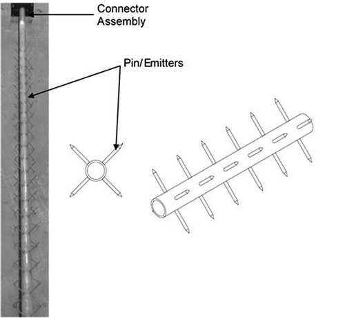
The performance of ESPs depends primarily on the discharge electrode design and spacing between discharge electrode and grounded plate (Chambers et al., Citation2001; Jędrusik et al., Citation2003; Nielsen and Andersson, Citation2009; Zhu et al., Citation2010; Xu et al., Citation2016). Typically, the corona current is emitted from sharp points also known as “emitters” on the discharge electrode. Corona discharge is controlled primarily by the electrode geometry, orientation, emitter geometry, and electrode distance from the grounded plate (Nielsen and Andersson, Citation2009; Zhu et al., Citation2010; Suleman Tahir et al., Citation2012; Kawakami et al., Citation2013). The uniform distribution of the corona current is also important characteristics of the discharge electrode design (Alam, Citation2011; Jędrusik and Świerczok, Citation2013). Wire discharge electrodes were commonly used until the advent of rigid discharge electrodes, shown in . Nielsen and Andersson (Citation2009) and Kawakami et al. (Citation2013) found that the most effective electrodes have emitters facing the flow direction. Nielsen and Andersson also found that selection of the round or sharp emitter tip depends on the spacing of the grounded plates.
The need for corrosion-resistant discharge electrodes arose with the development of wet ESPs, in which water is introduced to improve particle collection and removal. In addition, the exhaust stream is cooled enough to be saturated with water vapor. With the increase in cost of corrosion-resistant alloys and the decrease in the cost of carbon fiber fabrics, there has been an increased interest in carbon fiber composites for many applications (Strong, Citation2008; Qin et al., Citation2015). Although carbon fibers have been studied for discharge electrode applications, it must be used as a composite in the ESPs because structural rigidity is needed for the electrode (Lagarias, Citation1960). Carbon fiber composites have high specific strength, specific modulus, low density, excellent corrosion resistance, and application flexibility (Strong, Citation2008; Qin et al., Citation2015). Therefore, composite discharge electrodes have the potential to be a lightweight, corrosion-resistant substitute for traditional metal alloy electrodes in wet ESPs.
One of the concerns with carbon fiber composite electrode is electrical conductivity, which tends to be lower in the through-thickness direction of the composite. The higher contact conductivity or the through-thickness conductivity is desired for improving the hybrid electrode electrical performance. There have been several developments to improve the through-thickness conductivity of carbon fiber composites (Allaoui et al., Citation2002; Athanasopoulos and Kostopoulos, Citation2014; Kandare et al., Citation2015; Guadagno et al., Citation2015; Qin et al., Citation2015). Wang and Chung (Citation2000) examined the contact conductivity for unidirectional carbon layers and the cross-plies. They found that during the manufacturing process, an increase in curing pressure resulted in a decrease in the contact resistivity. Also, the electrical conductivity for the cross-ply is greater than the unidirectional ply. Likewise, Hirano et al. (Citation2016) concluded that the manufacturing process affects the average value of the through-thickness conductivity. In addition, Athanasopouos and Kostopoulos (2014) demonstrated that the resin-rich film prevents the contact between the carbon fiber and reduces the electrical conductivity in the through-thickness direction. Another method to improve the through-thickness electrical conductivity is through adding graphite nanoparticles and carbon nanotubes (Allaoui et al., Citation2002; Kandare et al., Citation2015; Qin et al., Citation2015) in the matrix. The in-plane conductivity for carbon fiber composites is relatively easy to achieve when compared with the through-thickness direction.
The primary objective of the research presented here is to showcase, for the first time, design and fabrication of a novel electrode that has a potential to replace the conventional metal electrode. Hereafter, this novel electrode will be referred to as hybrid composite electrode (HCE). The HCEs were fabricated from carbon fiber epoxy in combination with metal wire mesh in the shape of a long, thin tape and then were tested by connecting to a transformer-rectifier unit to generate a corona current. Since the corona was generated at each carbon fiber filament, these hybrid electrodes yielded corona fields that were denser and more uniform. A secondary objective was to decrease the contact resistivity among the fibers and the contact resistivity between the metal substrate and the carbon layers to improve HCE electrical performance. The performance of the HCEs was compared with a traditional metal electrode.
Experimental methods
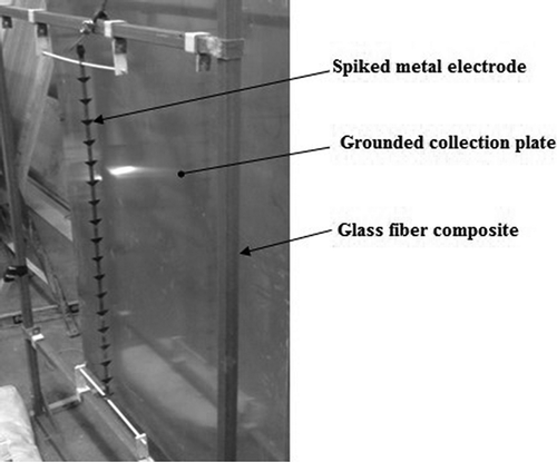
Several composite processing techniques were used to manufacture HCEs. These electrodes were then compared with conventional metal electrodes using common electrode metrics. It is worth mentioning that in order to eliminate the effects of other factors inside the ESP, such as temperature, dust particles accumulation, and pressure, tests were conducted outside the ESP chamber. In the present study, the preliminary tests were conducted using a custom-built test rig, shown in . The test setup comprised a grounded stainless steel plate and electrodes held in tension on an electrical grade glass fiber composite rig. The plate was 3.5 feet wide and 6 feet high. The electrode glass fiber composite rig was of the same size as the grounded plate. The distance between the electrodes and the plate was kept flexible, with cases ranging from 6 to 9 inches.
Electrode samples
Metal electrodes are available in a variety of configurations. The selection of the metal electrode configuration depends on many factors, such as the temperature and pressure inside the ESP, dust particulate size, etc. (Jędrusik et al., Citation2001; Xu et al., Citation2016; Yan et al., Citation2016;). In the present study, the spiked metal electrode was selected and used for the following reasons: (1) the design of the electrode was considered as a controlled corona-type (Parker, Citation2012) electrode, which was similar to the HCE; and 2) the electrode had higher discharge current (Xu et al., Citation2016; Yan et al., Citation2016) and comparable collection efficiency (at room temperature) (Xu et al., Citation2016) when compared with some other types of metal electrodes. The metal electrode was made using plain carbon steel tapes with triangular steel segments welded along the length of the electrode as depicted in the test rig in Figure 2. The spacing between discharge tips was approximately 2 inches.
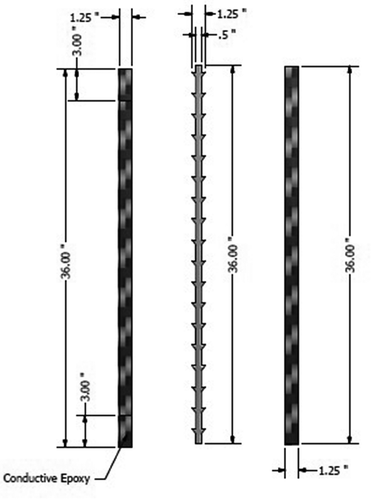
The HCE samples were produced with continuous carbon fibers having an electrical resistivity of 1.8 × 10⁻³ ohms·cm. Hand lay-up vacuum bagging and compression molding/hot press manufacturing processes were used to fabricate the HCE samples. Epoxy with AKSACA 3K A49 (Composite Envision, Wausau, WI) twill weave carbon fiber fabric in the form of Pre-preg sheets (VTP DA100; Composite Envision, Wausau, WI) were fabricated using compression molding. The samples from this type were called Pre-preg HCE. Plain weave 3K carbon fiber fabric with epoxy were fabricated using Hand lay-up vacuum bagging method. The samples from this type were named as Hand lay-up HCE. Samples from unidirectional carbon fiber with polypropylene (PP) matrix were fabricated using compression molding and were notated as PP HCE. All HCEs had the same configuration. Three stainless steel 60 × 60 mesh layers alternating with four carbon fiber layers were used to make a hybrid composite sheet, which was then cut into long tapes. The metal mesh in all HCEs served a dual role—as a conductive spine within the composite, as well as the connecting point for the high-voltage supply. It also provided spaces in the mesh pores for extra resin to flow during curing under pressure, which led to a good conductive contact between the metal mesh and the carbon fibers. The thickness of all electrodes (metal and HCEs) in the present study were kept at 0.08 ± 0.01 inch. Since the conventional epoxy matrix acts as an insulator increasing the resistance between the fiber bundles, conductive epoxy (CE), Carbon-Bond 61LP (xx, xx), was used in some samples to aid in the through-thickness conductivity. The samples from this type were called Hand lay-up CE HCE. shows the shape of the samples used and the overall dimensions.
Testing
In order to compare the electrodes’ performance, voltage-current (V-I) characteristic curves were generated for all samples. In all cases, measurements were taken from the effective edge or emitters of the electrodes. The baseline samples, as listed in ,were all tested at 6 inches from the grounded plate. The purpose of conducting the baseline tests was to study the V-I characteristics of each sample and select the configuration/material that had the desirable properties (higher discharge current, higher power) to be used as discharge electrodes. Additional V-I characteristic curves were generated at 7, 8, and 9 inches from the grounded plate up to the spark point—spark over. Steady-state power tests were also conducted for all samples at 6 inches distance from the grounded plate. The steady-state power is considered as the maximum voltage and current that the electrode can hold for 30 sec before sparking occurs. Finally, tests were conducted to record the corona onset voltage and the corona uniformity. Typically, the corona onset voltage is recorded at the initiation of discharge current (Parker, Citation2012); however, here, due to time lag between the corona onset and corona visibility, both (corona onset and corona visibility) values were recorded. Instrumentation used in the tests included (1) a Hipotronics Hipot tester 8100-10-A (xx, xx) with negative polarity to apply the voltage, (2) two digital multimeters to record both the voltage and the current, and (3) an ultraviolet (UV; full-spectrum Coolpix L30; xx, xx) camera to observe the corona. Before any data collection, a reference test was conducted to ascertain that the result were repeatable.
Table 1. Baseline samples.
Results and discussion
Baseline V-I curve tests with constant spacing
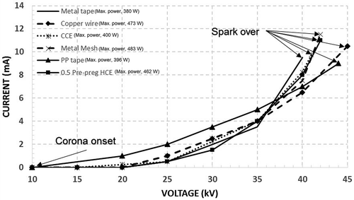
In these tests, the voltage was steadily ramped and the voltage and current values were recorded. The tests were conducted for six different samples at 6 inches distance from the grounded plate. Metal mesh, copper wire, carbon composite electrode (CCE), PP composite tape, metal tape, and HCE samples delivered spark over point powers of 483, 473, 400, 396, 380, and 462 W, respectively, as indicated in . The result showed comparable peak powers for the PP composite tape and the CCE. The corona onset voltage for PP composite tape was the lowest (10 kV) among all samples tested. The metal tape had the lowest power and its spark over voltage was the lowest as well (40 kV). For the PP composite tape, the current was the highest among all samples for voltage values up to 37 kV. This suggests that PP composite tape is perhaps more suitable for low-voltage applications. However, in the actual ESP, higher voltages are used. Also, due to low rigidity, PP composite tape is more prone to vibrations in the presence of gas flow and can cause lower spark over voltage. The V-I curves of the metal mesh, CCE, metal tape, and HCE were steeper at higher voltages, generating more current for small increase in the voltage; these tend to improve the collection efficiency of an ESP (Jędrusik and Świerczok, Citation2013).
The baseline tests suggest that the CCE had good discharge current, but it sparked earlier than other samples. On the other hand, the metal mesh had higher current density at the spark over voltage, but it didn’t have the appropriate structural rigidity to be used as a discharge electrode. By combining the metal mesh with the CCE, as evident in , the power of the HCE at the spark over point was improved by 15%, with a significant increase in the structural rigidity. Among the materials tested, the constituents of HCE and PP composite tape exhibited the greatest potential as electrode material to be compared with conventional electrodes in practice for further study.
V-I curve tests with variable spacing
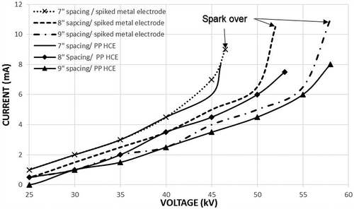
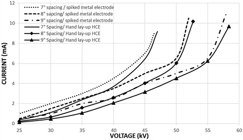
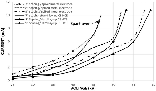
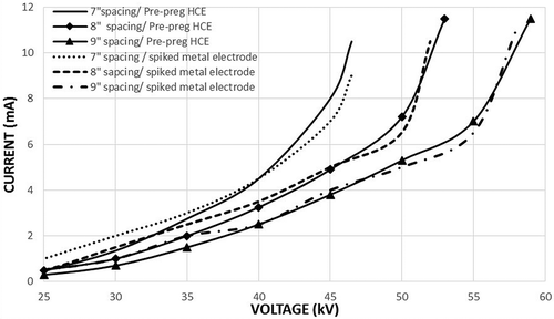
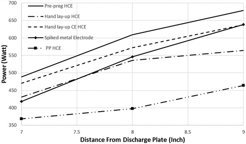
Typically in ESPs, higher discharge currents are desired for higher particulate collection efficiencies and these current values highly depend on spacing between the electrodes and the collection plate; therefore, in this stage of testing, all of the electrodes were tested at 7, 8, and 9 inches from the grounded plate. The voltage was steadily ramped, and both the voltage and current values were recorded. to depict the V-I curves of PP HCE, Hand lay-up HCE, Hand lay-up CE HCE, and Pre-preg HCE, respectively, and those of metal electrodes, along with spark over points. The curves were averaged for at least two tests for each electrode type. From the shape of the V-I curves, the corona current decreased (as expected) as the distance between the grounded plate and the discharge electrode increased for given value of the applied voltage.
As it can be seen in all V-I curves, the Pre-preg HCE had the same (and higher at some voltages) discharge current as the spiked metal electrode for all voltages past 40 kV. Also, it had the highest spark over points among all samples tested. The curves showed that the optimum spacing was 8 inches (since there were no improvements on the current values as the spacing increased from 8 to 9 inches). and show the effect of using the conductive epoxy at the ends of Hand lay-up HCE. The use of the conductive epoxy caused the electrode to spark at higher discharge current and higher voltages at 7- and 8-inch spacings. The PP HCE exhibited the lowest discharge current and the lowest spark over point. Further, at higher voltages, its V-I curve didn’t show a steep rise in current as compared with other HCEs and metal electrodes. This is probably due to the fact that the PP HCE had no metal mesh.
indicates the peak power at the spark over voltage and current for all discharge electrode samples. The Pre-preg HCE and PP HCE generated the highest and lowest powers, respectively, among all samples tested. The metal electrode power was higher than both the PP HCE and Hand lay-up HCE. The result indicated that the use of CE increased the power of the Hand lay-up HCE output at 7 and 8 inches and was almost equal at 9 inches as compared with the metal electrode. These results show that the Pre-preg HCE has the best performance in terms of the discharge current and power values.
Steady-state tests
In this test, the voltage was raised and held below the spark over point for more than 30 sec. All tests were conducted at 6 inches distance from the grounded plate. indicates the steady-state power for all samples. Although the steady-state power of Pre-preg HCE is comparable to the metal electrode, the current in the metal electrode fluctuated significantly; current spikes up to 13.4 mA were observed. It is well known that current fluctuation indicates the presence of unstable discharge corona, which reduces the ESP efficiency. In other words, a constant discharge current, as observed in HCE, shows presence of stable corona as reported by Yan et al. (Citation2016). The Hand lay-up CE HCE samples had the highest value of steady-state power, which may be attributed to the use of the conductive epoxy, which improved the power of the Hand lay-up sample by 16%.
Table 2. Steady-state test.
Corona onset tests
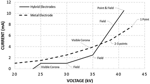
During these tests, corona was visually captured by using an UV full-spectrum camera (mentioned in the Testing section). indicates that one of the visible corona discharge initiated at 23 kV for the HCE, whereas for the metal electrode the visible corona discharge initiated at 34 kV electrode. The HCE maintained uniform corona field all the way to the spark over point where uniform field along with point corona was then observed. For the metal electrode, 2–3-point corona was observed past 38 kV, which then reduced to a single-point corona at spark over point. Comparing and , the corona was uniform across the length of the HCE, but not for the metal electrode. In fact, only approximately one-fourth of the metal electrode generated discharge corona at any given time. Further, the location of the point corona changed from one point to another randomly. Figure 12 shows the corona uniformity of the hybrid composite electrode at different applied voltages. The corona covered the spacing between the grounded plate and the electrode.
Figure 11. Three-point corona pattern for spiked metal. The left image was captured by using an UV camera.
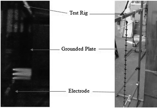
Figure 12. The uniform corona pattern for the HCE. (a) The corona at 54.3 kV and 8.5 mA. (b)The uniform corona. (c) The uniform corona at the spark over point.
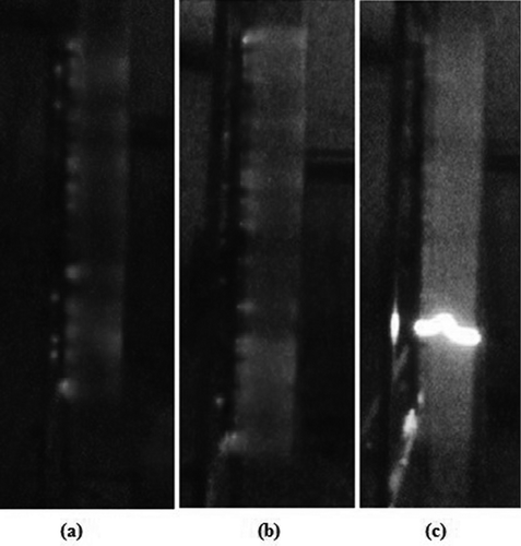
The particulate collection efficiencies and migration velocities are affected by the uniformity of corona (Landham et al., Citation1990; Jaworek et al., Citation2007; Jędrusik and Świerczok, Citation2013). Therefore, the uniform corona field generated by the HCE (as compared with the point corona of the metal electrode) will most likely improve the particulate collection efficiencies. This aspect will be presented in more details elsewhere. Traditional metal electrodes have several discharge corona points or pin emitters along its length, whereas in HCEs there are thousands of fibers running along and perpendicular to the length of the electrode that act as tiny emitters. These microemitters will easily release electrons and reduce ozone generation (Chen et al., Citation2006; Han et al., Citation2008, Citation2009; Kim et al., Citation2011). This means that the probability of charging the dust particles with the HCE will be significantly higher than any other type of metal electrodes.
During testing, it was also observed that many of the hybrid samples would sustain uniform corona fields up to 95% of the power range. The uniform corona densities may lead to more particulate charging even at lower power levels (which occurs in response to sparking) or at shorter distances from the plate. Finally, the ease of manufacturing of HCEs will have an advantage over conventional metal electrodes, as some designs are complex, time-consuming, and hence costly to manufacture.
Conclusion
The work done here presents, for the first time, results on the electrical performance of a novel hybrid electrode in controlled laboratory environment. The HCE was compared with the output of a typical metal electrode. It was found that HCE performance was comparable to the metal electrode sample. The HCE also exhibited uniform corona fields and steady power while maintaining similar and in some cases superior electrical performance as compared with metal electrodes. These preliminary results show distinct advantages of HCE as being compact, lightweight, and highly corrosion resistant and thus showcase a candidate electrode with significant potential to replace conventional metal electrodes in wet ESP systems and in other newer wet ESP technologies where compactness is highly desired (Ali et al., Citation2015, Citation2016).
Acknowledgment
The authors would also like to thank the anonymous referees for providing useful, constructive, and insightful feedback that resulted in a significant improvement of the original manuscript.
Funding
This work was completed in Ohio University’s Electrostatic Precipitator Laboratory, Athens, Ohio, and was supported through funds provided by the Babcock and Wilcox Company (GR-020-3200-08150), Ohio University Research Office, and Ohio University’s Russ College of Engineering and Technology.
Additional information
Funding
Notes on contributors
M. Ali
M. Ali and K. Alam are professors in the Department of Mechanical Engineering at Ohio University, in Athens, OH, USA.
K. Alam
M. Ali and K. Alam are professors in the Department of Mechanical Engineering at Ohio University, in Athens, OH, USA.
Y.T.A. Al-Majali
Y.T.A. Al-Majali and M. Kennedy are graduate research assistants in the Department of Mechanical Engineering at Ohio University, in Athens, OH, USA.
M. Kennedy
Y.T.A. Al-Majali and M. Kennedy are graduate research assistants in the Department of Mechanical Engineering at Ohio University, in Athens, OH, USA.
References
- Alam, K. 2011. Composite discharge electrode. US7976616 B2, issued July 12, 2011. http://www.google.com/patents/US7976616 ( accessed July 2016).
- Ali, M., H. Pasic, and K. Alam. 2015. Cross-flow wet precipitator. Presented at the 2015 International Pittsburgh Coal Conference, Pittsburgh, PA, October 5–8.
- Ali, M., H. Pasic, K. Alam, S.A.N. Tiji, N. Mannella, T. Silva, and T. Liu. 2016.Experimental study of cross-flow wet electrostatic precipitator. J. Air Waste Manage. Assoc. 66:1237–44. doi: 10.1080/10962247.2016.1209258.
- Allaoui, A., S. Bai, H.-M. Cheng, and J.B. Bai. 2002. Mechanical and electrical properties of a MWNT/epoxy composite. Compos. Sci. Technol. 62:1993–8. doi:10.1016/S0266-3538(02)00129-X
- Athanasopoulos, N., and V. Kostopoulos. 2014. A comprehensive study on the equivalent electrical conductivity tensor validity for thin multidirectional carbon fibre reinforced plastics. Composites Part B Eng. 67:244–55. doi: 10.1016/j.compositesb.2014.07.012.
- Bayless, D.J., M.K. Alam, R. Radcliff, and J. Caine. 2004. Membrane-based wet electrostatic precipitation. Fuel Process. Technol. 85:781–98. doi: 10.1016/j.fuproc.2003.11.025.
- Chambers, M., G.J. Grieco, and J.C. Caine. 2001. Customized rigid discharge electrodes show superior performance in pulp & paper applications. Presented at The International Conference on Electrostatic Precipitation, Birmingham, AL, May 14–17. http://www.thermalsystemsgroup.com/assets/rde_p-p_bham-recreated071811.pdf ( accessed August 2016).
- Chen, C.-H., B.-R. Huang, T.-S. Lin, I-C. Chen, and C.-L. Hsu. 2006. A new negative ion generator using ZnO nanowire Array. J. Electrochem. Soc. 153:G894. doi: 10.1149/1.2223557.
- Chen, T.-M., C.-J. Tsai, S.-Y. Yan, and S.-N. Li. 2014. An efficient wet electrostatic precipitator for removing nanoparticles, submicron and micron-sized particles. Sep. Purif. Technol. 136:27–35. doi: 10.1016/j.seppur.2014.08.032.
- Guadagno, L., U. Vietri, M. Raimondo, L. Vertuccio, G. Barra, B. De Vivo, P. Lamberti, G. Spinelli, V. Tucci, F. De Nicola, R. Volponi, S. Russo, 2015. Correlation between electrical conductivity and manufacturing processes of nanofilled carbon fiber reinforced composites. Composites Part B Eng. 80:7–14. doi: 10.1016/j.composites.2015.05.025.
- Han, B., N. Hudda, Z. Ning, and C. Sioutas. 2008. Enhanced unipolar charging of concentration-enriched particles using water-based condensational growth. J. Aerosol Sci. 39:770–84. doi: 10.1016/j.jaerosci.2008.05.004.
- Han, B., N. Hudda, Z. Ning, H.-J. Kim, Y.-J. Kim, and C. Sioutas. 2009. A novel bipolar charger for submicron aerosol particles using carbon fiber ionizers. J. Aerosol Sci. 40:285–94. doi: 10.1016/j.jaerosci.2008.11.005.
- Hirano, Y., T. Yamane, and A. Todoroki. 2016. Through-thickness electric conductivity of toughened carbon-fibre-reinforced polymer laminates with resin-rich layers. Compos. Sci. Technol. 122:67–72. doi: 10.1016/j.compscitech.2015.11.018.
- Jaworek, A., A. Krupa, and T. Czech. 2007. Modern electrostatic devices and methods for exhaust gas cleaning: a brief review. J. Electrostatics 65:133–55. doi: 10.1016/j.elstat.2006.07.012.
- Jędrusik, M., J.B. Gajewski, and A.J. Świerczok. 2001. Effect of the particle diameter and corona electrode geometry on the particle migration velocity in electrostatic precipitators. J. Electrostatics 51:245–51. doi:10.1016/S0304-3886(01)00047-X
- Jędrusik, M., and A. Świerczok. 2013. The correlation between corona current distribution and collection of fine particles in a laboratory-scale electrostatic precipitator. J. Electrostatics 71:199–203. doi: 10.1016/j.elstat.2013.01.002.
- Jędrusik, M., A. Swierczok, and R. Teisseyre. 2003. Experimental study of fly ash precipitation in a model electrostatic precipitator with discharge electrodes of different design. Powder Technol. 135–136:295–301. doi: 10.1016/j.powtec.2003.08.021.
- Kandare, E., A.A. Khatibi, S. Yoo, R. Wang, J. Ma, P. Olivier, N. Gleizes, and C.H. Wang. 2015. Improving the through-thickness thermal and electrical conductivity of carbon fibre/epoxy laminates by exploiting synergy between graphene and silver nano-inclusions. Composites Part A Appl. Sci. Manuf. 69:72–82. doi: 10.1016/j.compositesa.2014.10.024.
- Kawakami, H., T. Sakurai, Y. Ehara, T. Yamamoto, and A. Zukeran. 2013. Performance characteristics between horizontally and vertically oriented electrodes EHD ESP for collection of low-resistive diesel particulates. J. Electrostatics 71:1117–23. doi: 10.1016/j.elstat.2013.10.004.
- Kim, H.-J., B. Han, Y.-J. Kim, K.-D. Hwang, W.-S. Oh, S.-Y. Yoo, and T. Oda. 2011. Fine particle removal performance of a two-stage wet electrostatic precipitator using a nonmetallic pre-charger. J. Air Waste Manage. Assoc. 61:1334–43. doi: 10.1080/10473289.2011.603994.
- Lagarias, J.S. 1960. Discharge electrodes and electrostatic precipitators. J. Air Pollut. Control Assoc. 10:271–4. doi: 10.1080/00022470.1960.10467929.
- Landham, E.C., Jr., J.L. Dubard, and W. Piulle. 1990. The effect of high-voltage waveforms on ESP current density distributions. IEEE Trans. Ind. Appl. 26:515–22. doi:10.1109/28.55955
- Nielsen, N.F., and C. Andersson. 2009. Electrode shape and collector plate spacing effects on ESP performance. In Electrostatic Precipitation, ed. K. Yang, 111–118. Berlin, Germany: Springer. http://link.springer.com/chapter/10.1007/978-3-540-89251-9_23 ( accessed July 2016).
- Parker, K.R. 2012. Applied Electrostatic Precipitation. New York: Springer Science & Business Media.
- Qin, W., F. Vautard, L.T. Drzal, and J. Yu. 2015. Mechanical and electrical properties of carbon fiber composites with incorporation of graphene nanoplatelets at the fiber–matrix interphase. Composites Part B Eng. 69:335–41. doi: 10.1016/j.compositesb.2014.10.014.
- Strong, A.B. 2008. Fundamentals of Composites Manufacturing: Materials, Methods and Applications. Dearborn, MI: Society of Manufacturing Engineers.
- Suleman Tahir, M., M. Saleem, and M. Siebenhofer. 2012. Characterization of brush type discharge electrodes and impact of enhanced corona discharge on operation of electrostatic precipitators. J. Electrostatics 70:144–8. doi: 10.1016/j.elstat.2011.11.008.
- Wang, S., and D.D.L. Chung. 2000. Electrical behavior of carbon fiber polymer-matrix composites in the through-thickness direction. J. Mater. Sci. 35:91–100. doi:10.1023/A:1004744600284
- White, H.J. 1963. Industrial Electrostatic Precipitation. Boston, MA: Addison-Wesley.
- Xu, X., C. Zheng, P. Yan, W. Zhu, Y. Wang, X. Gao, Z. Luo, M. Ni, and K. Cen. 2016. Effect of electrode configuration on particle collection in a high-temperature electrostatic precipitator. Sep. Purif. Technol. 166:157–63. doi: 10.1016/j.seppur.2016.04.039.
- Yan, P., C. Zheng, W. Zhu, X. Xu, X. Gao, Z. Luo, M. Ni, and K. Cen. 2016. An experimental study on the effects of temperature and pressure on negative corona discharge in high-temperature ESPs. Appl. Energy 164:28–35. doi: 10.1016/j.apenergy.2015.11.040.
- Zhu, J., Y. Shi, X. Zhang, H. Yan, and K. Yan. 2010. Current density and efficiency of a novel lab ESP for fine particles collection. In Electrostatic Precipitation: 11th International Conference on Electrostatic Precipitation, Hangzhou, October 20-24, 2008, ed. Y. Keping, 65. New York: Springer Science & Business Media.

