ABSTRACT
Wet electrostatic precipitators (WESPs) are modern-era pollution control systems specifically designed to capture ultrafine particles as well as acid mist, highly resistive and sticky particles; however, this requires the use of expensive corrosion-resistant metal alloys. The work presented here is part of a continuing study at Ohio University aimed at reducing the cost of WESPs by using a novel combination of a polymer collector surfaces with a hybrid composite discharge electrode. In this study, a hybrid composite discharge electrode was tested, for the first time, inside a semi-pilot-scale experimental setup, with collection surfaces consists of a vertical array of strands. Particle laden gases were passed through this array of polymer ropes, which were kept wet by a small flow of water. The discharge electrodes were composite laminates of carbon fibers in a polymer matrix enclosing a metal mesh. The preliminary results showed that this new integrated system of composite discharge electrode and polymer collector surfaces can match or exceed the performance of a conventional metal alloy electrostatic precipitator (ESP) with metal discharge electrodes. There are additional advantages due to the system being compact, lightweight, and highly corrosion resistant.
Implications: This study focused on integrating and assessing performance of a novel hybrid composite electrode (HCE) inside semi-pilot novel cross-flow electrostatic precipitator at conditions typically observed in coal-fired power plant exhausts. The results were collected for particulate collection efficiencies and were compared with a rigid metal electrode. The HCE outperformed metal electrode by showing higher particulate collection efficiency. This result showcases substantial potential for these two new technologies (HCE and cross-flow system) as a substitute for conventional metal based wet ESPs.
Introduction
Electrostatic precipitators (ESPs) are primarily used in emission control of large-volume flows of exhaust gases such as those in coal-fired power plants. They are also capable of collecting several types of dust particles with a wide range of diameters and have collection efficiencies greater than 99% (Parker Citation2012; White Citation1963). However, efficiencies of dry ESP systems are quite low (70–80%) for the particle range of 3.93 to 78.74 micro inches (average diameter) due to the limitation on charging mechanisms of this range of the particle sizes (Ali, Pasic, and Alam Citation2015). Collection efficiency is also reduced by lower corona power levels caused by the accumulated ash layer on the collector electrodes, which increases the resistivity (Altman et al. Citation2001; Chang and Hsunling Citation1999).
Several studies have shown that wet electrostatic precipitators (WESPs) are more efficient for collecting sticky and highly resistive particles, acid aerosols, and nanoparticles (Bayless et al. Citation2004; Chen et al. Citation2014; Parihar, Hammer, and Sridhar Citation2015; Wang et al. Citation2016). These systems provide stronger corona power compared with dry ESPs due to the fact that the accumulated fly ash is washed off the collector plates, preventing any back corona. This effect improves the collection efficiency of the fine particles by more effective particle charging. Furthermore, because acid aerosols are usually soluble in water, it is easier to remove them by flowing water on the collector electrodes in WESPs. Although the introduction of water in WESPs made them more efficient than dry ESPs, it significantly increased their cost (4–6 times the base ESP cost) because of the use of expensive metal alloys in discharge and collection electrodes in order to resist corrosion arising from low pH values of water due to acidic gas collection (Silva, Moretti, and Liu Citation2015). In the presence of chlorides, the corrosion problem worsened. Further, as compared to dry ESPs, treatment of wastewater added additional cost ($2–3 per 1000 gallons of water). Another disadvantage of use of alloy materials in WESPs is being bulky and heavy, which makes the supporting structure and frames massive and costly. With the increase in cost of corrosion-resistant alloys and the decrease in the cost of polymer matrix composite materials, there has been an increased interest in use of these composites for many applications including WESPs.
The use of wet membrane-based grounded surfaces in WESPs was initiated at the ESP laboratory (Ohio University) and described in Hajrudin, Alam and Bayless (Citation1998), and was commercialized and has demonstrated many advantages (Shah and Caine Citation2008). First, the membrane-based collector plate facilitated the uniformity of the water delivery, which reduced the back corona at the dry spots. It also reduced clean water wastage (Du et al. Citation2016). The collection membranes were lighter in weight and resisted corrosion (Bayless et al. Citation2004). The discharge current was much stronger when the wet membrane was used (Wang et al. Citation2016). Recent developments at Ohio University’s ESP Laboratory include a patent pending (Hajrudin and Alam Citation2016) novel cross-flow WESP, which utilized multiple cells. Each cell had vertical columns of permeable material in the form of polypropylene ropes (as collection electrodes/field) placed in a cross-flow configuration within a flue gas stream. Details of this cross-flow ESP are available in the publication by Ali et al. (Citation2016). Since the gas flow is normal to collection electrodes in cross flow, this was a radical departure from all current WESP technologies where the gas flow is parallel to the collection electrodes/plates. The study showed potential for both weight and cost reductions.
The two major components for an ESP are the discharge electrode and the collection surface (also referred to as the collection electrode or ground electrode). Currently, many different shapes and designs of discharge electrodes are available. Majority of them have a set of pin emitters (the source of the corona) and are made out of steel, which tends to be heavy and will undergo corrosion unless special alloys are used.
In general, the collection efficiency of an ESP increases if the corona discharge intensity is high and covers the space between the discharge electrode and the grounded plates (Jędrusik and Świerczok Citation2013; Landham, Dubard, and Piulle Citation1990; Alam Citation2011). Extensive research has been conducted to optimize the shape and the configuration of discharge electrodes (Chambers, Grieco, and Caine Citation2001; Jędrusik, Gajewski, and Świerczok Citation2001; Quixian and Binxin Citation2009; Xu et al. Citation2016) and the arrangement within the ESP. There are several variables involved that may change the performance of a discharge electrode. These variables include, but are not limited to, orientation of the spark emitters, spacing between the grounded plate and the discharge electrode, pressure and temperature inside the ESP, spacing between the discharge electrodes, spacing between the spark emitters, dimension of the discharge electrode, shape of the spark emitters, and type of dust particles and diameter, flue gas residence time, and potential leakage path around the charged surfaces.
There is an increased interest in carbon fiber composites for potential use in many applications lately. Carbon fiber has high specific strength, specific modulus, low density, application/design flexibility (due to its fabrication/manufacturing methodology), and low cost (Strong Citation2008). The utilization of the carbon composite as a discharge electrode for ESP was invented and demonstrated by Alam (Alam Citation2011; Strong Citation2008; Alam Citation2015). He presented a new concept that was advantageous for reducing the weight, eliminating corrosion, and decreasing the cost of the discharge electrodes.
Although composite discharge electrodes in the previous studies had shown tremendous potential, the structural stiffness of the composite discharge electrodes, especially at large/commercial scale, presented challenges under the gas flow as even a small amount of discharge electrode vibration could potentially cause excessive sparking. To address these issues, a novel hybrid composite electrode (HCE) was developed earlier, with patent pending (Alam and Ali Citation2018), that combined the complementary properties of a metal and carbon fiber (Ali et al. Citation2017). The HCE provided excellent stiffness and abrasion and corrosion resistance. The performance of the HCE was compared with the output of a typical metal discharge electrode on a customized testing rig. It was concluded that the HCE exhibited uniform corona fields and steady power while maintaining similar and in some cases superior electrical performance as compared to metal discharge electrodes. These results showed distinct advantages of the HCE, in addition to being compact, lightweight, and highly corrosion resistant.
The study described here presents continuation of the work on the novel HCE. As such, the performance of the HCE was evaluated, for the first time, inside a semi-pilot WESP chamber at Ohio University. The V-I characteristic curves and collection efficiency tests for several arrangements of the HCE were compared to a “pipe and spike” metal discharge electrode (Ali et al. Citation2016) referred to as a “rigid discharge electrode” (RDE). Effect of discharge electrodes spacing, number of discharge electrodes, and gap of discharge electrode-grounded plate were investigated. Particulate collection efficiency tests were conducted for both the RDE and HCE inside the novel cross-flow WESP system developed in a separate previous study (Ali et al. Citation2016).
Methodology
HCE samples fabrication
In this study, HCE electrodes were fabricated in 6-ft lengths and used to conduct particulate collection efficiency tests. Prepreg HCE samples of twill weave AS4 carbon fiber sheets and epoxy system were used, with fiber volume fraction of 62% Fibre Glast 2000 with 2120 hardener. In order to add structural rigidity, 304 stainless steel (60 × 60) wire mesh sheets were inserted between carbon layers. The number of layers of stainless steel wire mesh and carbon fiber used were three and four, respectively, and layers were stacked together in an alternating pattern.
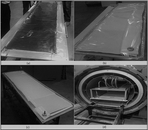
depicts stages of 6-ft prepreg HCE sample fabrication. In the first step (), the carbon fiber and wire mesh layers were stacked (three metal mesh inserted between four carbon fiber layers) on top of a flat metal mold, which was coated with a high-temperature mold-release agent. In the next step, the HCE laminate was covered with a release film, a breather, and a vacuum bag, as shown in . Afterward, the layers of HCE were compressed using vacuum as exhibited in . Two vacuum ports were positioned at the corners of the mold. The first one was used as the vacuum source, while the other one was used to measure the vacuum pressure. In the final stage, the layers of the HCE were cured using an autoclave, as in , at a temperature of 200°F for 2.5 hr and under a pressure of 58 psi. To monitor the curing process, thermocouples and pressure gauges were placed on the laminate to observe the temperature and pressure homogeneity during curing.
Figure 1. Stages of autoclave manufacturing of prepreg HCE: (a) stacking of carbon fiber and wire mesh layers; (b) vacuum bagging; (c) vacuum compression of HCE; (d) autoclave curing of HCE.
After curing, 1.25-inch-wide samples of HCE were cut from the cured hybrid laminate using a manual shear machine. It was expected that the use of the autoclave would uniformly pack the layers of prepreg HCEs. Also, it would decrease the thickness of the highly resistive resin layer by reducing cavities in the laminate. It was hypothesized that direct contact between the conductive metal mesh and the carbon fiber would most likely decrease the electrical resistivity of prepreg HCEs due to the formation of a conductive path among the HCE layers. This was confirmed to be case after microscopic analysis was conducted on a cross section of a prepreg HCE after the study was completed.
Samples testing
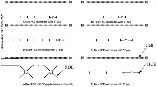
The electrical performance of prepreg HCE and RDE samples were first tested on a custom test rig outside the ESP chamber with discharge electrodes facing a cross-flow collection electrode cell. Both the HCE and the RDE had the same length (6 ft). The sets of the pin emitters in the RDE were equi-spaced along its length. In each set, there were four pins distributed radially. A high-power Nothelfer Winding Laboratories (model 102,462 Rev B) transformer/rectifier (T/R) unit was attached to the discharge electrodes as the negative source voltage. The discharge voltage was linearly ramped up to the spark over point, and both the voltage potential and the current were recorded simultaneously. and present the discharge (and collection) electrodes and the configurations that were tested in present study.
Table 1. Plan for electrodes testing with cross-flow cell (outside the ESP).
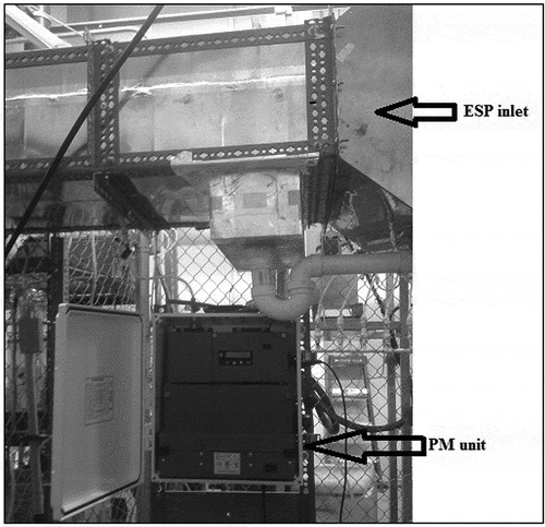
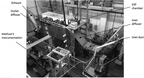
To conduct the experiments inside an ESP system, the existing semi-pilot ESP system of Ohio University’s ESP laboratory (shown in ) was used. The system consisted of an inlet diffuser, ESP housing/chamber, and outlet diffuser. The inlet duct of the system contained propane gas burners and a dust feeder with a dust delivery system. The outlet diffuser was connected to a variable frequency drive fan, which was capable of generating velocities up to 65 ft/sec across the cross-flow collection field. The overall length, height, and width of this system were 24, 10, and 4 ft, respectively. The ESP chamber was 8 ft long, 6 ft high, and was 2 ft wide. For all tests, fly ash added to the air flow had maximum, minimum, and average diameters of 348.03, 63.38, and 147.63 micro inches, respectively. These values were determined using a Beckman Coulter LS 13 320-MW particle size analyzer. All other variables such as temperature (130°F), humidity (80%), and dust concentration (1.87 × 10⁻⁶ lb/ft3) were kept constant. Note that the typical dust concentration that industrial scale WESPs system undergo ranges from 6.24 × 10⁻⁷ lb/ft3 to 5.30 × 10⁻⁶ lb/ft3. The V-I curves at clean conditions were generated before each test. The average power during the dust collection test and the number of sparks per minute (SPM) were recorded during each test. The particulate collection efficiency was measured using an MIE ADR-1500 particle monitor (PM) unit and Environmental Protection Agency (EPA) Method 5. shows the particulate mattter (PM) sampling unit, which was placed at the inlet, and an identical unit was placed at the outlet of the semi-pilot ESP system. The sampling probe was placed at nine different positions along the width and the height of the inlet and the outlet ducts. The sampling time for each point was 3 min. This process followed the methodology of conducting the dust particles collection efficiency tests as outlined by U.S. EPA, Document 2016–19,642 (EPA Citation2017). The efficiencies were calculated by dividing the difference between inlet and outlet particle concentrations with the inlet particle concentration.
Figure 3. The semi-pilot ESP test facility; the setup is 24 ft long, 10 ft high, and 4 ft wide (Ali et al. 2016).
The cross-flow collection electrode setup consisted of multiple cells, and each individual cell was 2 ft wide, 6 ft high, and 0.083 ft (1 inch) thick. Also, each cell had two rows of polypropylene ropes of 0.016 ft (0.19 inch) diameter that ran vertically up and down, creating a number of loops across each cell. These cells were housed in the ESP chamber. Gravity-assisted water film was supplied continuously along the length of the collection electrode ropes to develop a grounded collection surface, as well as to continuously flush down any particles collected on the surface. Refer to Ali et al. (Citation2016) for more details on cross-flow ESP system.
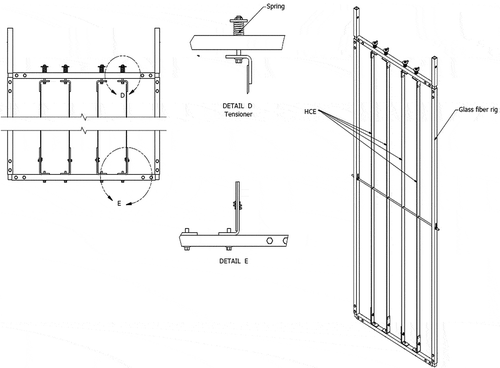
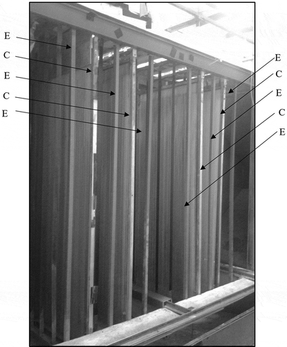
The spacing between the collection electrode and the discharge electrode was kept the same as the distance between the two types of discharge electrodes. The tests with only one electric field (E) installed before the collection electrode (C) were called EC tests, whereas tests with two electric field (before and after the collection electrode) were called ECE tests, and following this nomenclature, EC, ECE, and ECECE-ECECE tests were conducted. All HCE samples were positioned such that edges were oriented in the gas flow direction. In total, four HCEs were deployed in each electric field, and distance between any two HCEs was 5 inches. and show the EC, ECE, and ECECE-ECECE configurations inside the ESP chamber. The discharge electrodes were attached to a custom-built fiberglass frame that had a tensioner mechanism. This mechanism kept the discharge electrode under tension and reduced any vibration of HCE under gas flow. illustrates the design of the rig of discharge electrodes.
Figure 5. EC and ECE configurations inside semi-pilot ESP chamber. E stands for electrode and C stands for cell.
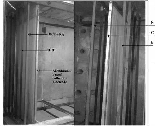
Figure 6. Isometric view of ECECE-ECECE configuration, where E stands for electrode and C stands for cell.
Each collection efficiency test was conducted two times and values were averaged. In order to find the net ESP particulate collection efficiency, first, dust particles dropout tests were conducted without the presence of both electric field and the cross-flow cells. These tests took into account particles that dropped out and collected on the floor and walls irrespective of the electric field. Second, cross-flow cell impaction tests were conducted without applying electricity to the system, and finally, total efficiency tests were conducted with the existence of electric field and cross-flow cells. Following the procedure already described, EC, ECE, and ECECE-ECECE configurations were tested. For each configuration, impaction, dropout, and total efficiencies were calculated.
Results and discussion
Testing results outside the ESP
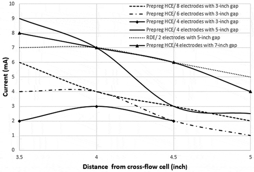
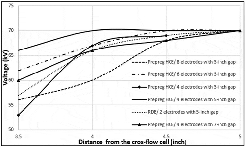
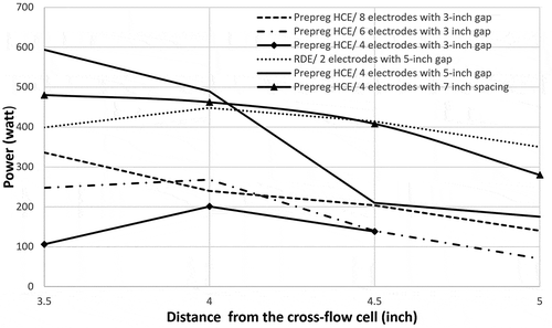
The effects of number of discharge electrodes and gap between discharge electrodes at different distances from the grounded plate were initially tested outside the ESP unit in room air (no gas flow). to depict discharge current, voltage at spark over points, and peak power for different configurations of prepreg HCE samples at different distances from the cross-flow cell. The prepreg HCE performances were then compared to the RDE electrode. The results indicated that the electrical performance of four HCE electrodes field having a 3-inch gap between the discharge electrodes was the lowest, whereas increasing the gap between HCE electrodes to 5 and 7 inches significantly increased the discharge current. The improvement in the discharge current (and power) when the gap between the discharge electrodes was increased was most likely due to the reduction in the interference of the electric field by neighboring discharge electrodes. The results also showed that the HCE sample at 5-inch gap generated highest current and voltages when compared to the RDE electrode (and all other configurations at 3.5-inch distance from cross-flow cell/grounded plate). At 4-inch distance from the grounded plate, the discharge currents (and power) for RDE and 5-inch gap HCE samples were more or less the same, and past this point RDE outperformed all HCE configurations with the exception of the 7-inch gap HCE setup. It is worth mentioning that HCE with 5-inch gap did not spark over at 4.5 and 5 inches distances from the grounded plate. Among all configurations, four HCE electrodes with 7-inch gap followed the RDE performance most closely. The discharge current values (and power) were similar to the discharge current of RDE at 4 and 4.5 inches distance from the grounded plate.
It was concluded that increasing the gap between the discharge electrodes in general increased the discharge current/power and decreased the sensitivity of change in current/power with distance from the grounded plate. Further, increasing the number of HCE electrodes while maintaining the same spacing monotonically increased the current/power; however, this effect was diffused as the distance from the grounded plate increased. Finally, the results showed that the HCE electrodes were more efficient at closer distances to the grounded plate as compared to RDE.
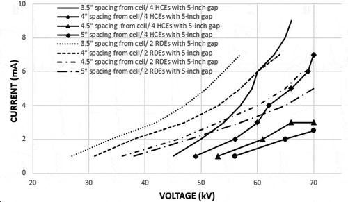
The comparison of V-I curves of the HCE and RDE is shown in . At distances closer to the cross-flow cell, the V-I curve of the HCE was steeper and it sparked over at a higher discharge current and voltage. It is well known that higher discharge current and voltage, especially for collecting ultrafine particles, are preferred for any ESP type.
Only two RDE electrodes could fit in the available space in present study. In contrast, several configurations of HCE electrodes could be used within the same available space. depicts the difference in dimensions of the discharge electrodes. It is clear that the use of RDE required more space in both longitudinal and lateral directions. In addition, the weight of HCE electrode was 0.64 lb, which was lower than typical RDE (Ali et al. Citation2016) by at least a factor of 10. This means that the internals of a WESP using HCE and corresponding housing will be more compact and light and will most likely have better performance.
Testing inside the ESP
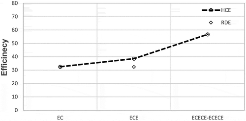
In this phase, HCE electrodes and RDEs were tested inside the Ohio University’s semi-pilot ESP chamber. All discharge electrodes were tested under the same conditions and the same configuration; that is, the electrodes gap was equal to their distance from the grounded plate. During initial tuning of the system, it was found that RDE caused excessive sparking at distances lower than 5 inches from the cross-flow cell; therefore, efficiency tests were conducted at 5 inches for both RDEs and HCEs. Each electric field, in the HCE case, had four discharge electrodes parallel to the flow direction, whereas in the case of metal discharge electrodes, two RDEs were installed in each electric field. The duration of each collection efficiency test was approximately 45 min. and list the particulate collection efficiencies along with the average values of maximum discharge voltages and currents during the tests. The efficiency results in graphical form are presented in . Each test was conducted two times and the average values were recorded and presented here. The results indicated that prepreg HCE electrode had the highest ESP collection efficiency. Also, there was no sparking (0 SPM) noticed during the tests. Since the prepreg HCE had no voltage breakdown, the dust particles charging process was expected to be more efficient. Therefore, the higher efficiency values of prepreg HCE were attributed to the uniformity of the discharge current (and corona) along the length of the discharge electrodes and zero sparking. On the other hand, during the test, it was observed that RDE produced some arcing, which affected the performance of cross-flow system. Finally, the efficiencies of the cross-flow system increased as additional electric fields (E) and cells (C) were added. An increase of 18.76% in net efficiency was noticed by adding a single electric field to the EC configuration. Likewise, 46.96% increase in net efficiency was recorded by changing the system configuration from ECE to ECECE-ECECE. lists the power level associated with each configuration and increasing efficiencies numbers correspond to increasing power levels for HCE. Although the power level for RDE was high for 4.5 inches spacing, as mentioned earlier, excessive sparking may have contributed to lower efficiency number as compared to its performance at 5 inches spacing.
Table 2. PM unit collection efficiency tests.
Table 3. Maximum voltage and current values during PM unit collection efficiency test.
Figure 13. Particular capture efficiencies at 5-inch distance for HCE and RDE, where E stands for electrode and C stands for cell.
It must be noted that the configuration used for HCE in efficiency study was four discharge electrodes with a 5-inch gap and 5-inch distance from the grounded plate. According to the V-I curve results of the previous section, this configuration (1:1) was not generating the highest discharge current. As mentioned earlier, in order to minimize sparking for RDEs (and to have identical testing configuration for fair comparison), a 5-inch distance between the collection and discharge electrode was selected. Since the results showed that HCE had the higher electrical performance at closer distances to grounded plate and increasing the gap between the discharge electrodes substantially increased the discharge current, it is expected that HCEs tested at one of the optimum configurations will most likely further improve the system’s collection efficiency. These aspects will be further researched and will be reported in the future.
Conclusion
In this study, the performance of a novel (patent pending) HCE, for the first time, was compared with metal RDE inside the semi-pilot ESP chamber by mimicking in-field operating conditions of coal-fired power plant exhaust. Prepreg HCE electric field exhibited better performance and as a result contributed to achieving higher particulate collection efficiency, with the added advantages of being corrosion resistant, lighter in weight, and lower in cost as compared to conventional metal discharge electrodes. Higher efficiency numbers of HCE electrodes were attributed to stable current with almost no sparks throughout the test, whereas metal discharge electrodes had current fluctuation and frequent sparking. Increasing the number of HCE electrodes in a row with a closer gap between them had minimal effect on the electrical performance, while increasing the gap between the discharge electrodes substantially enhanced the electrical performance. Finally, the current (and power levels) generated by HCE supported the use of HCE at lower distances from the grounded plate to achieve better electrical performance/particulate collection efficiencies. This showed significant potential toward making modern ESPs more efficient while reducing the overall system size, weight, and associated costs.
Acknowledgment
This work was completed in Ohio University’s Electrostatic Precipitator Laboratory, Athens, OH. The authors thank the anonymous referees for providing useful, constructive, and insightful feedback that resulted in a significant improvement of the original paper.
Additional information
Funding
Notes on contributors
M. Ali
M. Aliis a professor in the Department of Mechanical Engineering at Ohio University, in Athens, OH, USA.
Y.T.A. Al-Majali
Y.T.A. Al-Majali and M. Kennedy are (doctoral and master’s) research assistants in the Department of Mechanical Engineering at Ohio University, in Athens, OH, USA.
M. Kennedy
K. Alam is a professor in the Department of Mechanical Engineering at Ohio University, in Athens, OH, USA.
K. Alam
Y.T.A. Al-Majali and M. Kennedy are (doctoral and master’s) research assistants in the Department of Mechanical Engineering at Ohio University, in Athens, OH, USA.
References
- Alam, M. K. 2011. Composite Discharge Electrode. United States of America. Washington, DC, USA: USPTO.
- Alam, M. K. 2015. Carbon Fiber Composite Discharge Electrode. Washington, DC, USA: USPTO.
- Alam, M. K., and M. Ali. 2018. “Hybrid composite discharge electrode for use in an electrostatic precipitator.” USA Patent UOC-17006P.
- Ali, M., K. Alam, A. T. Y. Majali, and M. Kennedy. 2017. Novel hybrid composite discharge electrode for electrostatic precipitator. J Air Waste Manag. Assoc. 67 (9):1036–1045. doi:10.1080/10962247.2017.1334718.
- Ali, M., H. Pasic, and K. Alam. 2015. “Cross-flow wet precipitator.” International Pittsburgh Coal Conference. Pittsburgh.
- Ali, M., H. Pasic, K. Alam, S. Tiji, N. Manell, T. Silva, and T. Liu. 2016. Experimental study of cross-flow wet electrostatic precipitator. J Air Waste Manag. Assoc. 66 (12):1237–1244. doi:10.1080/10962247.2016.1209258.
- Altman, R., G. O. Pepri, W. Buckley, and I. Ray. 2001. Wet electrostatic precipitation demonstrating promise for fine particulate control-part I. Power Eng. 105:37–39.
- Bayless, D. J., M. K. Alam, R. Radcliff, and J. Caine. 2004. Membrane-based wet electrostatic precipitation. Fuel Process Technol. 85 (6–7):781–798. doi:10.1016/j.fuproc.2003.11.025.
- Chambers, M., G. J. Grieco, and J. C. Caine. 2001. “Customized rigid discharge electrodes show superior performance in pulp & paper applications.” International Conferene on Electrostatic Precipitation. Birmingham, AL, USA.
- Chang, C. L., and B. Hsunling. 1999. An experimental study on the performance of a single discharge wire-plate electrostatic precipitator with back corona. J Aerosol. Sci. 30:325–340. doi:10.1016/S0021-8502(98)00064-0.
- Chen, T.-M., C.-J. Tsai, S.-Y. Yan, and S.-N. Li. 2014. An efficient wet electrostatic precipitator for removing nanoparticles, submicron and micron-sized particles. Sep. Purif. Technol. 136:27–35. doi:10.1016/j.seppur.2014.08.032.
- Du, Q., L. Su, H. Dong, J. Gao, Z. Zhao, D. Lv, and S. Wu. 2016. The experimental study of a water-saving wet electrostatic precipitator for removing fine particles. J Electrost. 81:42–47. doi:10.1016/j.elstat.2016.03.004.
- Hajrudin, P., and M. K. Alam. 2016. “Wet electrostatic precipitator and method of treating an exhaust.” USA Patent PCT/US2015/055623.
- Hajrudin, P., M. K. Alam, and D. Bayless. 1998. “Membrane electrostatic precipitator.” USA Patent US6231643B1.
- Jędrusik, M., J. B. Gajewski, and A. J. Świerczok. 2001. Effect of the particle diameter and corona electrode geometry on the particle migration velocity in electrostatic precipitators. J Electrost. 51:245–251. doi:10.1016/S0304-3886(01)00047-X.
- Jędrusik, M., and A. Świerczok. 2013. The0r. J Electrost 71 (3):199–203. doi:10.1016/j.elstat.2013.01.002.
- Landham, E. C., Jr, J. L. Dubard, and W. Piulle. 1990. The effect of high-voltage waveforms on ESP current density distributions. Ind. Appl. IEEE Trans. On. 26 (3):515–5222. doi:10.1109/28.55955.
- Parihar, A. K. S., T. Hammer, and G. Sridhar. 2015. Development and testing of tube type wet esp for the removal of particulate mater and tar from producer gas. Renew. Energy 74:875–883. doi:10.1016/j.renene.2014.09.006.
- Parker, K. R. 2012. Applied electrostatic precipitation. In Parker, K.R. (Ed.), Springer Science & Business Media. London, UK: Blackie Academic & Professional.
- Quixian, F., and Z. Binxin. 2009. Study of using mixed discharge electrodes and mixed spacing of pole to pole for electrostatic precipitator. In Keping Yan (Ed.), Electrostatic Precipitation, 84–86. Berlin, Heidelberg: Springer.
- Shah, H., and J. H. Caine. 2008. “Next generation wet electrostatic precipitator.” In Proceedings of the International Technical Conference on Coal Utilization and Fuel Systems. Clearwater, FL, USA.
- Silva, A., A. Moretti, and T. Liu. 2015. “Continuos water washing in wet electrostatic precipitators reduces capital cost in the chinese market.” Electric Power Magazine.
- Strong, A. B. 2008. “Fundamentals of composites manufacturing: Materials, methods and applications.” Society of Manufacturing Engineers.
- United States Environmental Protection Agency. 2017. https://www.epa.gov/sites/production/files/2017-08/documents/method_5.pdf. Document # 2016-19642
- Wang, X., J. Chang, C. Xu, P. Cui, and C. Ma. 2016. Electrical characteristics of electrostatic precipitator with a wet membrane-based collecting electrode. J Electrost. 80:85–94. doi:10.1016/j.elstat.2016.02.003.
- White, H. J. 1963. “Industrial electrostatic precipitation.” Addison-Wesley.
- Xu, X., C. Zheng, P. Yan, W. Zhu, Y. Wang, X. Gao, Z. Luo, M. Ni, and K. Cen. 2016. Effect of electrode cnfiguration on particle collection in a high-temperature electrostatic precipitator. Sep. Purif. Technol. 166:157–163. doi:10.1016/j.seppur.2016.04.039.

