 ?Mathematical formulae have been encoded as MathML and are displayed in this HTML version using MathJax in order to improve their display. Uncheck the box to turn MathJax off. This feature requires Javascript. Click on a formula to zoom.
ABSTRACT
In the gasification of biomass, it is necessary to limit the amount of by-product tar and increase the yields of hydrogen (H2) and carbon monoxide (CO) (syngas). Therefore, we conducted gasification and reforming experiments on woody biomass using an electric tubular furnace, to evaluate the gas reforming and tar decomposition performance of a NiO/SBA-15 catalyst. As a result, we found that this catalyst is effective for H2 production. It is believed that the increase in H2 volume due to the catalyst occurs through a steam reforming reaction involving hydrocarbons, including methane (CH4), and the water-gas shift reaction. With respect to the influence of the gasifying agent on the reforming effect of the catalyst, the amount of generated carbon dioxide (CO2) and hydrogen (H2) increases because the shift reaction is promoted by supplying steam. On the other hand, it was inferred that the shift reaction rarely occurred because it approaches equilibrium by supplying O2. Furthermore, it is suggested that light aromatic hydrocarbons are decomposed by the catalyst.
Implications: The mesoporous silica catalyst NiO/SBA-15 was highly effective for H2 production and decomposition of light aromatic compounds in the gasification of woody biomass. In the catalyst reaction, supplying steam promoted H2 production. From thermodynamic analysis and discussion, it was also inferred that supplying O2 might prevent the water gas shift reaction. The results are useful for designing a process needed for rich H2 production and gas refining process for further use of syngas.
Introduction
In recent years, energy recovery from biomass, a renewable and carbon-neutral energy source, has been sought because of the demand for energy source diversification and carbon dioxide (CO2) reduction to address global warming. Gasification is one of the methods for recovering energy from solid biomass that includes waste. In this process, solid organic compounds are converted into gas, such as hydrogen (H2) and carbon monoxide (CO), through pyrolysis and high-temperature chemical reactions. The obtained gases are used for various purposes, such as in gas engines or as raw materials for chemical processing (Ruiz et al. Citation2013). However, in the gasification of biomass, it is necessary to limit the amount of by-product tar and increase the yields of H2 and CO (syngas). Tar is composed of various components, including volatile organic compounds and semivolatile compounds, which are gaseous at high temperatures but tend to condense below their boiling points and may cause clogging in piping and equipment (Devi, Ptasinski, and Janssen Citation2003, Energy Research Centre of the Netherlands, Citation2009). Gas containing excessive amounts of tar cannot be used in gas engines, for example, because of the possibility of equipment failure. Furthermore, tar contains a large amount of carbon and hydrogen, and when there is a large amount of tar, the gas yield of H2 and CO (etc.) is low. High-temperature reforming, in which tar is decomposed at 1000 °C or higher, is one of the processes for removing tar and increasing the yield of syngas. In order to maintain the high temperature, oxygen has been supplied to partially combust the gases and organic compounds (Yamada, Shimizu, and Miyoshi Citation2004), and plasma technology has also been tried (Fabry et al. Citation2013). However, a large amount of energy is required for such oxygen supply and plasma generation. Therefore, a gas reforming process that operates at low temperatures with less energy consumption is desired, and attention has thus been paid to developing a catalyst that can promote such reforming at relatively low temperatures, in the range of 700–800 °C.
Various catalysts have been studied for application to biomass gasification. Corella et al. investigated calcined natural ores (dolomite, magnesite, and calcite) as gasification catalysts and reported that dolomite had a relatively strong effect on tar decomposition performance (Corella, Toledo, and Padilla Citation2005; Delgado, Aznar, and Corella Citation1996; Narváez et al. Citation1996). However, they also reported that the produced gas contained very fine particles because of the softness of calcined dolomite, and successful tar decomposition performance was not obtained when the tar concentration was high. Noble metal catalysts such as rhodium (Rh) and platinum (Pt) have also been investigated in this context, and excellent tar decomposition performance was observed (Nishikawa et al. Citation2008; Tomishige, Asadullah, and Kunimori Citation2004). In this case, however, there is a problem in the high cost of the catalysts. For this reason, catalysts using nickel (Ni) and iron (Fe) (Parparita et al. Citation2015), which are less expensive than noble metals, have been vigorously developed. In fact, Ni is well known for its excellent performance as a steam reforming catalyst for hydrocarbons and is therefore found in many commercial catalysts (Igarashi Citation2000). Several studies have investigated the use of such commercially available catalysts in biomass gasification (e.g., Kawamoto, Wu, and Kuramochi Citation2009). Garcia et al. reported the effect of a developed Ni-aluminum (Al) catalyst on tar and light hydrocarbons in gas reforming and the level of H2 and CO generation (Garcia et al. Citation2002, Citation1998). In a study using a catalyst composed of Ni and natural ore (olivine), it was reported that the tar concentration was reduced by 75% or more and H2 concentration increased by 8% or more (Pfeifer, Rauch, and Hofbauer Citation2004). Novel catalysts, with Ni (carried by some chars) as an effective component, have also been developed and are expected to decompose tar (Hatori et al. Citation2017; Li and Takarada Citation2013). Nickel oxide (NiO) carried by SBA-15 mesoporous silica (NiO/SBA-15) has also been studied (Lu et al. Citation2017; Lu, Ju, and Kawamoto Citation2014; Lu and Kawamoto Citation2013). Mesoporous silica is a porous material with tiny pores 2–50 nm in diameter, a high specific surface area, and an ordered structure. NiO is not thought to be an effective steam reforming catalyst (Furusawa and Tsutsumi Citation2005). However, NiO catalysts are often used in biomass gasification without prior reduction (Lu et al. Citation2017; Wang et al. Citation2011), because the production gas contains reducing gases such as H2 and CO and thus the NiO is reduced by the production gas under reforming conditions (Gao et al. Citation2017; Pfeifer, Rauch, and Hofbauer Citation2004). Kawamoto et al. conducted gasification and reforming experiments on woody biomass and refuse paper and plastic fuel (RPF) using a NiO/SBA-15 catalyst (Kawamoto and Lu Citation2016). The gasification and reforming temperatures were 750 °C. The results showed that hydrogen production by the catalyst was efficient when the NiO content was 20% (weight %), and that catalyst with 40% NiO achieved a 99.3% tar decomposition rate. In this experiment, calcium oxide (CaO) reagent was applied to the top surface of the catalyst layer in order to prevent sulfur poisoning and dust contamination of the catalyst. However, CaO may itself have catalytic effects (Garcia, Alarcon, and Gordon Citation1999); thus, the catalytic effect of NiO/SBA-15 alone remains unclear. The purpose of the present study, then, was to evaluate the gas reforming and tar decomposition performance of NiO/SBA-15 catalyst alone.
Experimental
Materials
Feedstock
For feedstock, white pellets made from wood (pine, cedar, etc.) without bark were pulverized and screened to obtain particle sizes ranging from 0.6 to 2 mm. Proximate and ultimate analyses of the material are shown in . The ash content of this raw material was very low, and there were only trace amounts of chlorine (Cl) and sulfur (S), which are causes of catalyst poisoning.
Table 1. Proximate and ultimate analyses of the raw material used.
Catalyst
A NiO catalyst, supported by SBA-15 mesoporous silica and synthesized by the postsynthesis method (Lu, Inagi, and Endo Citation2011), was employed. All the material reagents were purchased from Wako Pure Chemical Industries, Osaka, Japan. First, pluronic P123 was dissolved in deionized water at room temperature, and then tetraethylorthosilicate (TEOS) and hydrochloric acid were added and stirred with a stirrer. The obtained mixture was aged at 80 °C for 24 hr in an oil bath. Next, the solid product was filtered, washed thoroughly with deionized water, dried at room temperature for 12 hr in a drafter, and calcined at 550 °C for 10 hr in an electric furnace to obtain SBA-15. The SBA-15 was then added to ethanol (99.5%) containing dissolved nickel nitrate hexahydrate (Ni(NO3)2·6H2O; 98.0%) and dispersed for 4 hr under ultrasonic radiation. The mixture was then dried at room temperature and calcined at 500 °C for 5 hr. This synthesis method has been empirically verified, and the detailed characterization of the obtained catalyst has been empirically confirmed (Lu and Kawamoto Citation2013). The proportion of supported NiO was 20% (weight %), the percentage recommended in a previous study (Kawamoto and Lu Citation2016) for sufficient hydrogen yield and low catalyst cost. The nitrogen adsorption/desorption measurement of synthesized catalyst was conducted at −196 °C, using an adsorption measurement instrument (BELSORP-mini II; MicrotracBEL, Osaka, Japan). Roughly 0.1 g of catalyst was pretreated at 100 °C for 2 hr in a vacuum, and the specific surface area was calculated using the Brunauer-Emmett-Teller (BET) method. The pore size distribution was calculated using the Barrett-Joyner-Halenda (BJH) method. The catalyst had a pore size of 3.94 nm, and a specific surface area of 289 m2/g.
Apparatus and methods
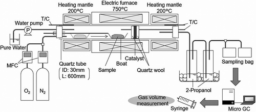
A schematic diagram of the experimental setup used in the gasification and reforming experiments is shown in . First, a raw material sample of 1 g was placed on a magnetic boat, which was then placed in front of the electric furnace. When the furnace temperature reached 750 °C, the boat was inserted into the center of the furnace. The boat was heated for 120 min and then withdrawn to the previous position in front of the furnace. N2 and O2 were supplied to the furnace using a mass-flow controller (model 3660; Kojima Instruments, Kyoto, Japan), which was adjusted so that the total flow rate was 50 mLN/min. To supply steam to the furnace, water was pumped into the front region of the electric furnace and evaporated in a quartz tube heated by a heating mantle, while a heating mantle at the rear of the electric furnace served to reduce the amount of tar agglomeration. The heating temperature was 200 °C, which was lower than the heat resistance temperature of the silicone stopper.
Then, 1 g of catalyst (~3 mL in volume) was placed in the furnace and sandwiched in quartz wool. The generated gas was passed through 2-propanol contained in impingers installed in an ice bath in order to remove tar and moisture; after which it was collected in a 1-L gas sampling bag. The sampling bags were exchanged for new ones roughly every 15 min; however, if a bag became full in less than 15 min, it was exchanged at that time. The gas sampling time was 120 min during heating, and 45 min after the end of heating.
Experimental conditions
Experiments were carried out under the following four conditions, in order to investigate the influence of differences in gasifying agents. In Run 1, only N2 was used as a carrier gas. In Run 2, a small amount of O2 was added to the N2 carrier. In Run 3, steam was supplied with the N2. And in Run 4, steam and a small amount of O2 were supplied with N2. The O2 flow rate was set so that the equivalence ratio (ER), as defined by the following equation, would be 0.2:
The amount of supplied steam was determined by the rated capacity of the water pump used (0.45 mL/min). As in Kawamoto and Lu (Citation2016), the gasification and catalytic reforming temperatures were 750 °C. In addition, when NiO/SBA-15 was synthesized by the direct synthesis method, the catalyst was calcined at 800 °C for 2 hr (Lu and Kawamoto Citation2012). These reports indicate that NiO/SBA-15 has thermal stability at 750 °C.
Measurements
The respective amounts of H2, O2, N2, CH4, CO, CO2, and hydrocarbons CnHm (C2H4, C2H6, C3H8, i-C4H10, n-C4H10) in the generated gas collected in the sampling bags were determined using a thermal conductivity detection (TCD) gas chromatograph (490 Micro GC; Agilent Technologies Japan, Tokyo, Japan), with Molsieve 5A (Ar carrier; Agilent Technologies Japan) and PoraPLOT Q (He carrier; Agilent Technologies Japan) columns. In addition, after this analysis, the volume of gas in the sampling bags was measured with a syringe. Any material remaining on the boat after the experiment was collected as solid residue, and its weight was measured.
The tar adhering to the tube at the furnace outlet was washed with acetone and collected, together with the 2-propanol, in the impingers, and the amount of tar was then measured. As the solvent contained moisture as well as tar, it was dehydrated with sodium sulfate and the tar components were extracted with dichloromethane. A large amount of water collected in the solvent when steam was supplied. Therefore, when steam was supplied, the same (dehydration and extraction) treatment was conducted, but in this case after the sample had first been shaken in dichloromethane and dehydrated. After the above treatment, the solvent was volatilized at 80 °C, enabling the tar to be weighed. In Run 1 only, the tar components in the solvent before treatment were analyzed using a gas chromatograph–mass spectrometer (GC-MS) (GC: 6890/MS: 5973N; column: DB-5MS, length 30 m × inner diameter 0.25 mm, film thickness [df] 0.25 μm; Agilent Technologies Japan), and the solvent was adjusted with 2-propanol so that the amount of solvent would be the same regardless of whether a catalyst was used or not.
Results and discussion
Amount of gas, tar, and solid residue resulting from gasification and catalytic reforming
summarizes the experimental conditions and the results obtained for the amount of generated gas, tar, and solid residue. The volume of generated H2 increased significantly (by approximately 190–270 mL), under all conditions, when using the catalyst. The volume of generated CO2 also increased, by approximately 20–80 mL, under all conditions, due to the catalytic reaction. In contrast, the volume of generated CH4 decreased from 61–63 to 47–51 mL, and that of CnHm decreased from 26–28 to 14–19 mL, when using the catalyst. The amount of generated CO increased, due to the catalytic effect, in Runs 1 and 2; but when steam was supplied, the amount was roughly the same (Run 4) or slightly less (Run 3) when the catalyst was used.
Table 2. Measurement conditions and results for gas, tar, and solid residue.
Gasification behavior under noncatalytic conditions
The effect of gasifying agents on the gasification results was also investigated. shows the accumulated gas volume over the sample heating time, under non-catalytic conditions, for each gas. The displayed time is the total time that elapsed after the sample was inserted into the electric furnace.
Figure 2. Gas volume accumulation over time without catalyst. Run 1: N2; Run 2: N2 + O2; Run 3: N2 + steam; and Run 4: N2 + O2 + steam. (a) H2; (b) CO; (c) CO2; (d) CH4 and CnHm.
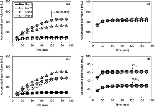
In Run 1, the accumulated gas volume of all gases remained unchanged after 30 min, meaning that the volatile compounds in the sample rapidly volatilized when the sample was inserted into the furnace and the generated gas was thereby discharged from the apparatus within 30 min. On the other hand, in Runs 2–4, the volume of CO2 continuously increased, even after 30 min. In the case of Run 2 (where oxygen was supplied), this was because the solid residue reacted with the supplied oxygen and produced CO2. As shown in , the amount of solid residue in Run 1 was 130 mg, and in Run 2 it was 56 mg, with a difference of 74 mg. The difference between the amounts of CO2 generated in Runs 1 and 2 (186 mL – 48 mL = 138 mL) was equivalent to 74 mg of carbon, similar to the difference in the amount of solid residue. This clearly suggests that the increase in CO2 was due to oxidation of the solid residue. However, in Runs 3 and 4, where steam was supplied, not only CO2 but also H2 continued to increase, even after 30 min. It is inferred that the increase in CO2 and H2 after 30 min is owing to the water-gas reactions of carbon in the solid residue, expressed in the following equations:
Generally, it is thought that the reaction in eq 2 occurs at 1000 °C or higher, and that the reaction in eq 3 occurs when the temperature decreases (Morita Citation1979). Therefore, at the temperature of 750 °C used in this experiment, it can be inferred that the amount of CO2 will increase, instead of CO, because of the reaction expressed in eq 3. However, it was observed that the CO level in Runs 3 and 4 increased slightly after 30 min, when compared with Runs 1 and 2. Therefore, the reaction in eq 2 may also be taking place to some extent. The increase in the amount of H2 in Run 4, where oxygen was supplied, was less than in Run 3. Similarly, in Run 2, where again oxygen was supplied, the amount of generated H2 was slightly less than in Run 1. From these results, it was inferred that the supplied oxygen reacted not only with the solid residue but also, to a lesser extent, with the generated H2. CH4 and CnHm were not generated after 30 min, and the entire amount generated was similar under all conditions.
Effect of catalytic reforming
Based on the gas generation behavior observed above, the effect of catalytic reforming was investigated. The accumulated gas volume during sample heating is shown in – for Runs 1–4, respectively.
Figure 3. Gas volume accumulation over time with/without catalyst (Run 1). (a) H2; (b) CO; (c) CO2; (d) CH4 and CnHm.
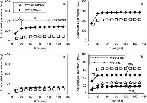
Figure 4. Gas volume accumulation over time with/without catalyst (Run 2). (a) H2; (b) CO; (c) CO2; (d) CH4 and CnHm.
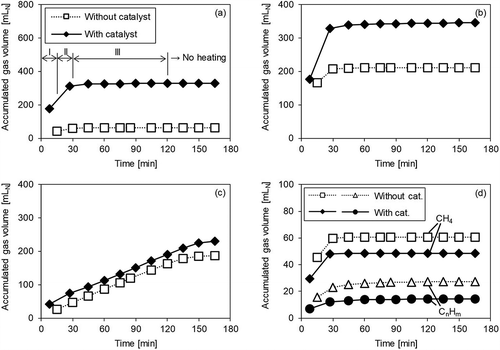
Figure 5. Gas volume accumulation over time with/without catalyst (Run 3). (a) H2; (b) CO; (c) CO2; (d) CH4 and CnHm.
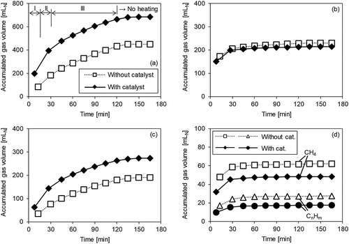
Figure 6. Gas volume accumulation over time with/without catalyst (Run 4). (a) H2; (b) CO; (c) CO2; (d) CH4 and CnHm.
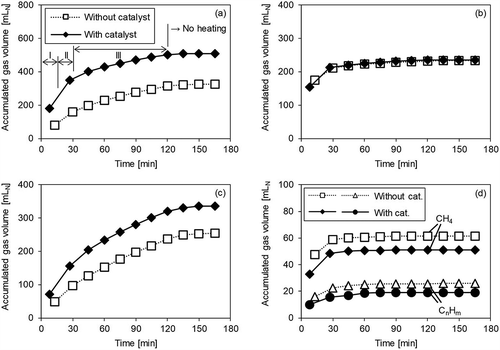
In Run 1 (), none of the gases increased in volume after 30 min, even when using the catalyst. There were differences in the amount of gas generated, depending on the presence or absence of the catalyst; however, these differences occurred between the beginning of heating and 30 min. Therefore, it is thought that the differences in gas generation behavior in Run 1 were due to the reforming of gas generated during volatilization. In this study, the sample heating duration was divided into three periods: (I) the first half of volatilization (first sampling bag); (II) the second half of volatilization (second sampling bag); and (III) after volatilization was completed (after 30 min). The amount of H2 () was significantly increased by the catalyst during Periods I and II. In the case of CO (), in Period I, the respective generation profiles and amounts were very similar with and without the catalyst; however, in Period II, an increase in the amount of CO was observed when the catalyst was used. In the case of CO2 (), an increase in gas volume was also observed but the increase was less than that of H2 and CO. However, the behavior of CH4 and CnHm () differed significantly from the other gases, with the gas volumes decreasing in Periods I and II when a catalyst was employed.
Given the above results, it can be inferred that H2, CO, and CO2 are generated by the decomposition of hydrocarbons such as CH4 through steam reforming and the water-gas shift reaction. The relevant reactions are expressed in the following equations:
From and the reactions above, the increase in CO2 in Period I may be attributed to some measure of the CO generated by the steam reforming reaction in eq 4 being changed to CO2 by the shift reaction in eq 5. Then, in Period II, it may be inferred that the reaction in eq 4 continued but the reaction in eq 5 stopped. It is considered that in the above reactions, the H2O generated by pyrolysis of the sample was consumed, and it is inferred that almost no shift reaction occurred in Period II because most of the H2O produced by pyrolysis had been already consumed by this time.
Next, in Run 2 (), where oxygen was supplied, it was observed that the H2 level increased in Periods I and II, and then CO increased in Period II, as shown in Run 1. CH4 and CnHm decreased in Periods I and II, and the decreased amount was also mostly the same as in Run 1. Therefore, the reactions in eqs 4 and 5 occurred even when O2 was supplied. The CO2 level continued to increase, even in Period III, but the rate of increase was constant at approximately 1 mL/min, regardless of the presence or absence of the catalyst. On the other hand, the rate of increase in CO2 in Periods I and II was 2–5 mL/min when the catalyst was used. This suggests that the increase in CO2 due to the catalyst occurred in Periods I and II, similarly to Run 1.
shows the results for Run 3, where steam was supplied. It may be observed that the amount of H2 was increased by the catalyst in Periods I and II. In Period III, the rate of increase in H2 was roughly the same regardless of the presence or absence of the catalyst. The amount of CH4 and CnHm decreased with the catalyst in Periods I and II, similarly to Runs 1 and 2. The decrease in CH4 and CnHm was similar to that in Runs 1 and 2; thus, it was expected that the effect of the catalyst promoting the reaction in eq 4 would not change much, even when steam was supplied. On the other hand, unlike in Runs 1 and 2, no increase in the CO level due to the catalyst was observed in Run 3. It can be seen that in Period II, whereas the CO level increased in Runs 1 and 2, the CO2 level increased significantly in Run 3. This suggests that the CO gas obtained by steam reforming (eq 4) due to the catalyst was used in the shift reaction (eq 5) in the atmosphere of excess steam and H2 and CO2 were generated. Moreover, the CO level slightly increased due to the reaction in eq 2 with no catalyst, whereas this was not observed when the catalyst was used. It may thus be inferred that the CO was used in the catalytic promotion of the reaction in eq 5.
Finally, shows the results for Run 4, with supplied O2 and steam. Here, similar catalytic effects to those in Run 3 were observed. In other words, the CO2 level increased because of the catalyst, and it is thought that the shift reaction occurred after the steam reforming reaction. However, the amount of H2 increase due to the catalyst was less than in Run 3. Furthermore, in Run 4, the CO level remained somewhat elevated in Period III, regardless of the presence or absence of catalyst. From this result, it may be inferred that, unlike in Run 3, the shift reaction did not occur in Period III in Run 4. This result may be interpreted in terms of chemical equilibrium. The equilibrium constant for the water-gas shift reaction, Keq=equilibrium constant, is given in eq 6 (Byron Smith, Loganathan, and Shantha Citation2010):
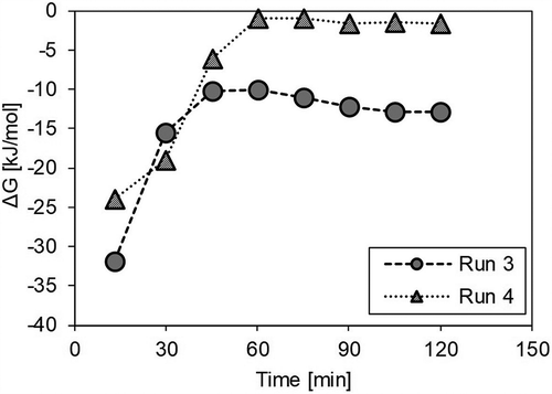
where T is the absolute temperature (K). Here, when T = 1023 K (750 °C), Keq = 1.31. The Gibbs free energy change in the water-gas shift reaction, ΔG (kJ/mol), is given in eq 7:
where R is the gas constant (8.314 × 10⁻³ kJ/K·mol) and Pgas is the partial pressure (Pa) of each gas. Pgas was here calculated from the concentration of gas collected in the sampling bags and the amount of supplied steam. shows ΔG as calculated from the experimental results for Runs 3 and 4 without a catalyst. When ΔG is zero, the reaction is in equilibrium. In Run 4, ΔG rapidly approached zero in Period III (after 30 min), and it is considered that the shift reaction was almost in equilibrium. This is thought to be due to the increase in CO2, which is the product of a forward-shift reaction through oxidation of the solid residue in Run 4. In light of the foregoing, it may be seen that the shift reaction hardly occurred in Period III in Run 4 because it had reached equilibrium and thus there was almost no difference observed in the CO level with or without the catalyst.
Tar decomposition by catalyst
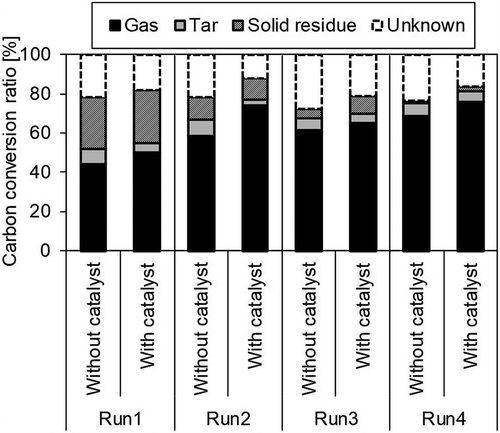
From , the respective calculated rates of decomposition of gravimetric tar due to the catalyst were Run 1: 17.6%; Run 2: 48.1%; Run 3: −5.0%; and Run 4: 4.9%; with the rates in Runs 3 and 4 being remarkably low. One plausible reason is that the space velocity of the catalyst was increased; that is, the contact time between the tar and the catalyst was reduced because of the greater amount of gas due to the supplied steam. The catalyst showed gravimetric tar decomposition capability in Runs 1 and 2, but the effect was considered to be small.
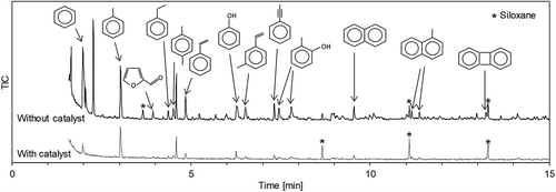
shows the rates of conversion of the carbon contained in the sample into gas, tar, and solid residue, respectively. When the catalyst promotes only the reactions in eqs 4 and 5, the carbon-gas conversion rate does not change when it is employed. However, here, the rate clearly increased when using the catalyst, indicating that when using the catalyst, not only did a gas reforming reaction occur but also a gas increase reaction due to tar decomposition. Furthermore, the sum of the gas and tar conversion rates of carbon also increased with the catalyst, suggesting that the amount of gas volume increase was greater than the amount of tar decomposition. Tar is a complex material consisting of a number of compounds. It may be roughly classified into GC-detectable tar, of which the molecular weight is less than 350 g/mol, and higher-molecular-weight tar (Van Paasen et al. Citation2002). However, here, part of the GC-detectable tar evaporated with the solvent during volatilization. Therefore, it may be conjectured that the increase in gas volume was greater than the tar decomposition because the GC-detectable tar was decomposed into gas by the catalyst. A comparative qualitative analysis of the composition of a resulting tar sample, with and without catalyst, using GC-MS (Run 1), is shown in , where the various compounds are identified based on spectral databases. The peaks of the aromatic hydrocarbons such as benzene are reduced, indicating that they were decomposed by the catalyst. The analytical results, then, suggest that the generated gas volume increased because the catalyst decomposed the light aromatic hydrocarbons.
Conclusion
We conducted gasification and reforming experiments on woody biomass using an electric tubular furnace, to evaluate the gas reforming and tar decomposition performance of a NiO/SBA-15 catalyst. We found that this catalyst is effective for H2 production. It is believed that the increase in H2 volume due to the catalyst occurs through a steam reforming reaction involving hydrocarbons, including CH4, and the water-gas shift reaction. With respect to the influence of the gasifying agent on the reforming effect of the catalyst, the amount of generated CO2 and H2 increases because the shift reaction is promoted by supplying steam. On the other hand, the supply of O2 increases the CO2 concentration, and it is inferred that the shift reaction thereby approaches equilibrium, which rarely occurs. Finally, with respect to tar decomposition, it is suggested that light aromatic hydrocarbons are decomposed by the catalyst.
Additional information
Notes on contributors
Naoko Inoue
Naoko Inoue is a researcher at Kobelco Eco-Solutions Co., Ltd., and a doctoral student at Okayama University in Japan.
Toshiya Tada
Toshiya Tada is a researcher at Kobelco Eco-Solutions Co., Ltd., in Japan.
Katsuya Kawamoto
Katsuya Kawamoto is a professor at Okayama University in Japan.
References
- Byron Smith, R. J., M. Loganathan, and M. S. Shantha. 2010. A review of the water gas shift reaction kinetics. Int. J. Chem. React Eng. 8. doi: 10.2202/1542-6580.2238.
- Corella, J., J. M. Toledo, and R. Padilla. 2005. Catalytic hot gas cleaning with monoliths in biomass gasification in fluidized beds. 3. their effectiveness for ammonia elimination. Ind. Eng. Chem. Res. 44:2036–45. doi:10.1021/ie040244i.
- Delgado, J., M. P. Aznar, and J. Corella. 1996. Calcined dolomite, magnesite, and calcite for cleaning hot gas from a fluidized bed biomass gasifier with steam: Life and usefulness. Ind. Eng. Chem. Res. 35:3637–43. doi:10.1021/ie950714w.
- Devi, L., K. J. Ptasinski, and F. J. J. G. Janssen. 2003. A review of the primary measures for tar elimination in biomass gasification processes. Biomass Bioenerg. 24:125–40. doi:10.1016/S0961-9534(02)00102-2.
- Energy Research Centre of the Netherlands, Netherlands, 2009. Thersites the ECN tar dew point site. http://www.thersites.nl/default.aspx (accessed October 22, 2018).
- Fabry, F., C. Rehmet, V. J. Rohani, and L. Fulcheri. 2013. Waste gasification by thermal plasma: A review. Waste Biomass Valorization. 4:421–39. doi:10.1007/s12649-013-9201-7.
- Furusawa, T., and A. Tsutsumi. 2005. Comparison of Co/MgO and Ni/MgO catalysts for the steam reforming of naphthalene as a model compound of tar derived from biomass gasification. Appl. Catal. 278:207–12. doi:10.1016/j.apcata.2004.09.035.
- Gao, N., Y. Han, C. Quan, and C. Wu. 2017. Promoting hydrogen-rich syngas production from catalytic reforming of biomass pyrolysis oil on nanosized nickel-ceramic catalysts. Appl. Therm. Eng. 125:297–305. doi:10.1016/j.applthermaleng.2017.07.028.
- Garcia, L., A. Benedicto, E. Romeo, M. L. Salvador, J. Arauzo, and R. Bilbao. 2002. Hydrogen production by steam gasification of biomass using Ni-Al coprecipitated catalysts promoted with magnesium. Eng. Fuel. 16:1222–30. doi:10.1021/ef020035f.
- Garcia, L., M. L. Salvador, J. Arauzo, and R. Bilbao. 1998. Influence of catalyst weight/biomass flow rate ratio on gas production in the catalytic pyrolysis of pine sawdust at low temperatures. Ind. Eng. Chem. Res. 37:3812–19. doi:10.1021/ie9801960.
- Garcia, X. A., N. A. Alarcon, and A. L. Gordon. 1999. Steam gasification of tars using a CaO catalyst. Fuel Process Tech. 58:83–102. doi:10.1016/S0378-3820(98)00087-3.
- Hatori, T., K. Morishita, N. Kannari, and T. Takarada. 2017. Study of nickel adsorption properties of chemically treated woody biomass. J. JPN. Ind. Eng. 96:139–43.
- Igarashi, A. 2000. Recent topics on production and use of hydrogen. J. Hydrogen Energy Syst. Soc. Jpn. 25:62–70.
- Kawamoto, K., and B. Lu. 2016. Gasification and reforming of biomass and waste samples by means of a novel catalyst. J. Mater Cycles Waste Manag. 18:646–54. doi:10.1007/s10163-016-0533-9.
- Kawamoto, K., W. Wu, and H. Kuramochi. 2009. Development of gasification and reforming technology using catalyst at lower temperature for effective energy recovery: Hydrogen recovery using waste wood. J. Environ. Eng. 4:409–21. doi:10.1299/jee.4.409.
- Li, L., and T. Takarada. 2013. Conversion of nitrogen compounds and tars obtained from pre-composted pig manure pyrolysis, over nickel loaded brown coal char. Biomass Bioenerg. 56:456–63. doi:10.1016/j.biombioe.2013.05.028.
- Lu, B., Y. Inagi, and A. Endo. 2011. Characteristics of SBA-15 synthesized by one-step method. J. Nanosci. Nanotechno. 11:2361–67. doi:10.1166/jnn.2011.3142.
- Lu, B., Y. Ju, T. Abe, and K. Kawamoto. 2017. Hydrogen-enriched producer gas production and chemical conversion to usable gas product through biomass gasification using NiO nanoparticles dispersed on SBA-15. J. Nanosci. Nanotechno. 17:6190–97. doi:10.1166/jnn.2017.14454.
- Lu, B., Y. Ju, and K. Kawamoto. 2014. Conversion of producer gas using NiO/SBA-15 obtained with different synthesis method. Ind. J. Coal. Sci. Technol. 1:315–20. doi:10.1007/s40789-014-0037-y.
- Lu, B., and K. Kawamoto. 2012. Direct synthesis of highly loaded and well-dispersed NiO/SBA-15 for producer gas conversion. RSC Adv. 2:6800–05. doi:10.1039/c2ra20344h.
- Lu, B., and K. Kawamoto. 2013. Preparation of the highly loaded and well-dispersed NiO/SBA-15 for methanation of producer gas. Fuel. 103:699–704. doi:10.1016/j.fuel.2012.09.009.
- Morita, Y. 1979. Bases on the reaction of coal gasification. J. Fuel. Soc. Jpn. 58:141–47. doi:10.3775/jie.58.141.
- Narváez, I., A. Orío, M. P. Aznar, and J. Corella. 1996. Biomass gasification with air in an atmospheric bubbling fluidized bed. effect of six operational variables on the quality of the produced raw gas. Ind. Eng. Chem. Res. 35:2110–20. doi:10.1021/ie9507540.
- Nishikawa, J., T. Miyazawa, K. Nakamura, M. Asadullah, K. Kunimori, and K. Tomishige. 2008. Promoting effect of Pt addition to Ni/CeO2/Al2O3 catalyst for steam gasification of biomass. Catal. Comm. 9:195–201. doi:10.1016/j.catcom.2007.05.045.
- Parparita, E., M. A. Uddin, T. Watanabe, Y. Kato, J. Yanik, and C. Vasile. 2015. Gas production by steam gasification of polypropylene/biomass waste composites in a dual-bed reactor. J. Mater Cycles Waste Manag. 17:756–68. doi:10.1007/s10163-014-0308-0.
- Pfeifer, C., R. Rauch, and H. Hofbauer. 2004. In-bed catalytic tar reduction in a dual fluidized bed biomass steam gasifier. Ind. Eng. Chem. Res. 43:1634–40. doi:10.1021/ie030742b.
- Ruiz, J. A., M. C. Juárez, M. P. Morales, P. Muñoz, and M. A. Mendívil. 2013. Biomass gasification for electricity generation: Review of current technology barriers. Renew. Sust. Energ. Rev. 18:174–83. doi:10.1016/j.rser.2012.10.021.
- Tomishige, K., M. Asadullah, and K. Kunimori. 2004. Syngas production by biomass gasification using Rh/CeO2/SiO2 catalysts and fluidized bed reactor. Catal. Today. 89:389–403. doi:10.1016/j.cattod.2004.01.002.
- Van Paasen, S. V. B., J. H. A. Kiel, J. P. A. Neeft, H. A. M. Knoef, G. J. Buffing, U. Zielke, K. Sjostrom, C. Brage, P. Hasler, P. A. Simell, et al. 2002. Guideline for sampling and analysis of tar and particles in biomass producer gases - final report documenting the guideline. R & D work and dissemination Report ECN-C-02-090. Energy Research Center of the Netherlands. doi:10.1044/1059-0889(2002/er01).
- Wang, T., Y. Li, C. Wang, X. Zhang, L. Ma, and C. Wu. 2011. Synthesis gas production with NiO-MgO/γ-Al2O3/cordierite monolithic catalysts in a pilot-scale biomass-gasification-reforming system. Energ. Fuel. 25:1221–28. doi:10.1021/ef1015268.
- Yamada, S., M. Shimizu, and F. Miyoshi. 2004. Thermoselect waste gasification and reforming process. JFE Tech. Rep. 3:20–24.

