 ?Mathematical formulae have been encoded as MathML and are displayed in this HTML version using MathJax in order to improve their display. Uncheck the box to turn MathJax off. This feature requires Javascript. Click on a formula to zoom.
ABSTRACT
Volatile organic compounds (VOCs) contribute to the formation of ground-level ozone. This causes the phenomena of haze and photochemical smog pollution. Recently, the leak detection and repair (LDAR) program was required to implement in China’s petroleum industry on the background of the huge emissions from equipment leaks. This paper analyzed and compared the application of LDAR program in four petroleum refineries and six typical processing units in these refineries. The results showed that non-flanged connectors, flanges, valves, and open-ended lines were the most common components, which accounted for over 99% in these refineries. And over half were non-flanged connectors. About 0.2% to 0.4% of all components were found to leak and emitted up to 91.8% of VOCs, especially the leaking valves and open-ended lines. And over 88.5% of VOC emissions were from high leaking components. The VOC emissions reduced 42% to 57% by repairing 42% to 81% of leaking components. And 90% of the reduction was achieved by repairing high leaking components. Besides, under the same processing capacity, the gas fractionation unit and continuous catalytic reforming unit have a higher average number of components, leaking components and VOC emissions than the other four units. Finally, this paper proposed some problems and suggestions during the implementation of LDAR program. These findings can enhance and improve the effectiveness of LDAR program, and establish a comprehensive VOCs control system, which provides a scientific basis and technical support for the government and refineries.
Implications: Recently, China required industries to implement leak detection and repair (LDAR) program to control volatile organic compound (VOC) emissions, especially the petroleum industry. In this paper, we analyzed and compared the LDAR program implementation in four refineries and six typical processing units in these refineries. The results indicate that the implementation of LDAR program was highly effective in petroleum industry. The comparison helps us to enhance the effectiveness of LDAR program by locating the high VOC emission components and units, which provides technical support for the government and refineries in developing specific regulations and plans.
Introduction
With the deepening of industrialization, urbanization and the rapid increase in energy consumption, the world has been experiencing serious air pollution problems, especially in China (Altieri and Stone Citation2016; Liu and Diamond Citation2005; Sunder Raman and Kumar Citation2016; Zhuang et al. Citation2014). In recent years, air pollution in China has shifted from traditional coal smoke pollution, which was dominated by dust and SO2 pollution, to regional pollution, which was dominated by fine particulate matter and ozone. Environmental problems such as haze, and photochemical smog, have become one of the most serious environmental issues in many cities and regions in China (Guo et al. Citation2012; Hao et al. Citation2007; Kim and Lee Citation2018; Liu et al. Citation2017; Wang et al. Citation2010).
Recent studies (Huang et al. Citation2014; Zhao et al. Citation2015) have found that severe haze pollution was driven by the secondary organic aerosol (SOA) formation in China. Moreover, several studies indicate that volatile organic compounds (VOCs) were crucial precursors for the formation of SOA and ozone (Han et al. Citation2017; Wang et al. Citation2012; Zhang et al. Citation2008; Zhu et al. Citation2018). The VOCs emitted from various sources pose a significant health risk to humans, which can cause asthma, allergies, headaches, chronic diseases, and damage to the body organs and central nervous system in the long term, especially in heavily industrialized regions (Jecha et al. Citation2014; Li, Uttarwar, and Huang Citation2013; Mustafa et al. Citation2017; Saalberg and Wolff Citation2016).
The VOC emissions in China reached 31.12 million tons in 2015 (Zhang et al. Citation2018), and the anthropogenic VOC emissions reached 16.5 ~ 23.2 million tons from 2005 to 2013 (Wei et al. Citation2016). And the VOC emissions from industrial processes accounted for about 40% of the total anthropogenic VOC emissions (Hong-Li et al. Citation2017; Mo et al. Citation2015; Wei et al. Citation2014).
However, the control of VOC emissions from industrial process in China is focused on the end treatment technologies with low VOC removal efficiency and high operating costs (Jaleh et al. Citation2019; Jecha et al. Citation2014; Martinez et al. Citation2007). Therefore, China has made efforts to analyze and promote the management and control of VOC emissions from industrial processes, especially from the petroleum industry (An et al. Citation2014; Chen and Liang Citation2013; Liang et al. Citation2015; Ling et al. Citation2011).
The VOCs can be released to the atmosphere through leakage, venting, and evaporation of the materials and products throughout the petroleum industry processes (An et al. Citation2014; Jia et al. Citation2016). Therefore, based on different production conditions and pollutant emission types, the Ministry of Ecology and Environment of China (MEE) divided the emission sources of VOCs in petroleum industry into 12 categories. Among that, the source of equipment leaks was one of the major emission sources, which contributed about 25% of VOC emissions. The leakage of equipment components exists in processing units and auxiliary facilities, which can be triggered by many factors, such as excessive operations, erosion, looseness, and seal cracks.
The leak detection and repair (LDAR) program was widely used in controlling VOC emissions from equipment leaks. Developed countries such as the United States, the European Union, and Canada have implemented the LDAR program to control VOC emissions since the 1980s and achieved significant results (63% emission reduction for petroleum refineries) (EPA Citation2007). In order to promote and develop the implementation of LDAR program, the government issued a series of policies, standards, and requirements (see Table S1 in Supporting Information). For the petroleum industry, the Guidelines for Petroleum and Refining Industries Leak Detection and Repair (MEE Citation2015) is crucial for VOCs control and LDAR program implementation. These documents put forward that all petroleum refineries need to develop and implement LDAR program by the end of 2017.
With the growing interest in and the success of LDAR program, there is a large body of recent literature about LDAR program in China. However, most of the literature was focused on the application of LDAR program in one unit or petroleum refinery. There are no studies on comparing the application of LDAR program in different units and refineries (Khan, Al Sulaiti, and Bashir Citation2015).
This study compared the implementation of LDAR program in four petroleum refineries, analyzed the number and distribution of equipment components and leaking components, and estimated the VOC emissions, as well as the leak repair results. Also, this study compared VOC emissions in six typical processing units. Meanwhile, this study discussed the economics of the LDAR program. In the end, some problems and suggestions were put forward and discussed to improve the effectiveness of LDAR program. This study provides a baseline for government and suggestions to improve the LDAR program application, leakage management of VOC emissions from equipment components, and make effective emission reduction related plans.
Materials and methods
Scope
The LDAR logs of four refineries and six typical processing units in these refineries were collected. The refineries and the units selected in this study comprise a range of ages and sizes, all the refineries have higher processing capacities than the average value (4.12 million tons/year in 2018 from the National Energy Administration), except for A refinery. The total processing capacity of these refineries that are all located in the Northeast or Northwest China account for 18% of the national total processing capacity. The four refineries are all belonging to the same company. And the LDAR program implementation was conducted by the same third-party company in 2016 or 2017 for the first time. The details of the refineries are listed in .
Table 1. Basic information of four refineries.
LDAR program
Leak Detection and Repair program is a technology that controls material leakage throughout the industrial process. Components, which have the potential to leak in process units, should be quantitatively detected by using stationary or mobile detection devices. Leaking components must be repaired by taking effective measures within a specified time to control the leakage and reduce environmental pollution.
The LDAR program was performed in the four refineries by the procedures stipulated in the Guidelines for Petroleum and Refining Industries Leak Detection and Repair. All refineries and units were operating normally throughout the test period. The LDAR procedures and requirements were described in section 2 and section 3 in the Supporting Information.
VOC emissions estimation
In this paper, the VOC emissions refer to the VOC emissions from the source of leakage of equipment components in refineries. The VOC emissions were estimated using the correlation equations method, which was put forward in the Guidelines for Petroleum and Refining Industries Leak Detection and Repair. Correlation equations method is the most widely used method to calculate the VOC emissions (Ellis and Lackaye Citation1989; EPA Citation1999).
This method specifies three different emission rates based on different screening value (SV) ranges. When a screening value is below 1 ppmv, the default zero emission rates in are used to estimate TOC emissions. If the screening value is up to 50,000 ppmv, then the applicable values for pegged emission rates in are used. When a screening value is between 1 and 50,000 ppmv, the correlation equations emission rates in are used (see EquationEq. 1)(1)
(1) .
Table 2. Equipment leak rate for petroleum equipment components.
Where:
eTOC = Emission rate of TOC for a specific type of equipment (kilograms per hour [kg/h])
SV = Screening value (ppmv)
e0 = Default zero emission rate for a specific type of equipment (kg/h)
ep = Pegged emission rate for a specific type of equipment (kg/h)
ef = Correlation equations emission rate for a specific type of equipment (kg/h)
Values by equipment type can be seen in .
The correlation equations for equipment components in provide emissions in terms of TOC (including methane and ethane). To calculate the emission rate for VOCs, use the EquationEq. 2(2)
(2) .
Where:
eVOC = Emission rate of VOCs for a specific type of equipment (kg/hr)
WFVOC = Average weight fraction of VOCs in the stream
WFTOC = Average weight fraction of TOC in the stream
If the weight fraction of VOCs in the TOC is not provided, the default value 1 will be applied for calculation. In this paper, the value of weight fraction was 1.
The equipment components emissions in a specific period can be estimated by multiplying equipment emission rates and operating period (see EquationEq. 3)(3)
(3) .
Where:
Eequipment = Annual VOC emissions (kg/yr)
eVOC,i = Emission rate of VOCs for the specific type of equipment (kg/hr)
n = Number of the specific type of equipment component
H = Operating period (hours/year), which was assumed to be 8,760 hours/year in this paper
Results and discussion
According to the Guidelines for Petroleum and Refining Industries Leak Detection and Repair, all applicable components in A, B, C, and D refineries were detected and monitored for the first time. The number of components was directly counted based on the LDAR log. The VOC emissions were estimated using the correlation equations method.
Equipment components
Total equipment components
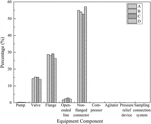
The numbers and distribution of equipment components in these refineries are shown in and .
Table 3. Numbers of equipment components in different refineries.
As we can see from , the total number of equipment components in these refineries is varied. Among these refineries, D refinery has the highest amount of equipment components owing to its highest processing capacity and the number of processing units. Meanwhile, the other three refineries have a similar number of equipment components due to their similar processing capacities and units.
Although there are differences in the total number between equipment components, the distribution of these components is similar (see ). The overwhelming majority of components are constituted by non-flanged connectors, which account for about 55%. And most of them are found in air-cooled plugs, sampler components, level gauges, etc. Flanges, valves and open-ended lines are followed behind, taking up 28%, 15%, and 2.3%, respectively. The reason why the percentage of flanges is nearly twice that of the valves is that many component sets (which contains two flanges and one valve) are used for connecting the fluid media.
However, pumps, compressors, agitators, pressure relief devices, and sampling connection systems have much lower proportions, and the total proportion of them is about 0.3%. This distribution result is similar to the one which the U.S. Environmental Protection Agency (EPA) found (EPA Citation2007).
Leaking components
The number and distribution of leaking components which concentrations higher than the leak definitions in these refineries are shown in and .
Table 4. Numbers of leaking components in different refineries.
From , we can see the numbers of leaking components in these refineries are varied. And D refinery has the largest number of leaking components. For these refineries, approximately 0.2% to 0.4% of the total components are leaking components. This result is lower than the average leak percentage of China’s petroleum refineries (1.46%), which was proposed by Zhang, who sort out and compared the LDAR implementation of several typical processing units in 10 refineries in several provinces through literature review (Zhang Citation2016). This is because the LDAR program in the literature was conducted from 2012 to 2013, which lacked unified LDAR standard specifications and leak concentrations at that time. On the other hand, the leak percentage in the literature was targeted at the processing units, not the whole refinery. Moreover, the average leak percentage is lower than the average leak percentage of 17 U.S. facilities (5.0%) (EPA Citation1999) and equal to the leak percentage of a refinery in Canada (0.25%) (CCME Citation1993).
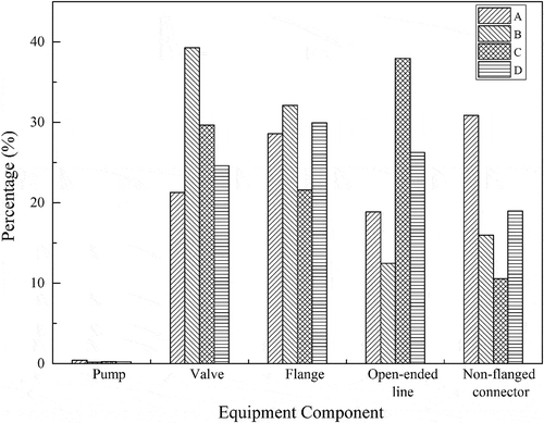
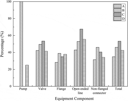
Valves, flanges, non-flanged connectors, and open-ended lines are all primary leaking components for different refineries and account for a similar proportion (see ). Nearly it is half of the leaking components that are high leaking components (concentration exceeds 10,000 ppmv) (see ). And for the leaking component, components that have the highest average leaking proportion also have the highest average high leaking proportion.
Figure 3. Distribution of high leaking components in total leaking components in different refineries.
Among the leaking components, the open-ended lines have the highest average leak percentage (3.0%) and an average high leaking percentage (1.6%). According to , the open-ended lines only account for 2.3% of the total components. This means that although the number of open-ended lines is small, the leak percentage is high, which indicates that the open-ended lines are prone to leak, and the enterprises should pay attention to them. However, the non-flanged connectors show an opposite trend, in which the highest component percentage (55%) owns the lowest leaking percentage (0.12%). And most leaking non-flanged connectors come from the bottom of the heating furnace burner. Because the media of the burner are fuel gas, which has a high vapor pressure and volatility at ambient temperatures.
VOC emissions
VOC emissions from equipment components
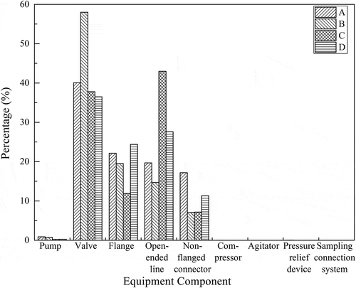
The VOC emissions from all equipment components and the distribution are shown in and .
Table 5. VOC emissions from all equipment components (unit: tons/year).
As we can see from , D refinery has the highest quantity of VOC emissions due to its high number of units and equipment components. For the other three refineries, a refinery that has a high number of equipment components has low VOC emissions and vice versa. The distribution of VOC emissions from equipment components is similar to the equipment components, with valves, flanges, non-flanged connectors, and open-ended lines taking up high proportions (see ). Valves emit a relatively high quantity of VOCs (account for about 43%) although it has a low proportion of total components (15%). By contrast, non-flanged connectors have the highest proportion of total components (55%) and emit a relatively small quantity of VOCs (account for about 11%).
VOC emissions from leaking components
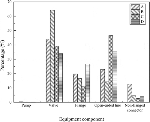
The VOC emissions from leaking components and the distribution are shown in and .
Table 6. VOC emissions from leaking components (unit: tons/year).
As we can see from and , the number and VOC emissions from leaking components have a similar distribution, which leaking valves, open-ended lines, and flanges emit a high quantity of VOCs, accounting for about 45.4%, 29.8%, and 18.6%, respectively. In addition, the distributions of the VOC emissions from the total components and the leaking components are similar. This phenomenon, on the other hand, verifies that the VOCs are mainly emitted from leaking components.
According to , VOC emissions from leaking components are responsible for the majority of the total VOC emissions from all components, which account for up to 91.8%. This means that up to 91.8% of VOC emissions in different refineries are generated by 0.2% to 0.4% leaking components, especially the leaking valves and open-ended lines. This result was also found by other research (EPA Citation1978; Epperson et al. Citation2007). Besides, 96.4% of the VOCs from leaking components were emitted from high leaking components. The results demonstrate that the primary way to control VOC emissions in China’s petroleum refineries is to develop an effective monitoring and maintenance program to locate this small percentage of high leaking components so that repairs can be scheduled.
Table 7. Different proportion of VOC emissions.
From the perspective of refining capacity per million tons per year, we can find that B refinery emits the highest VOCs and D refinery emit the lowest. This is because the B refinery was established earlier than the other three refineries. At that time, the manufacturing, installation, and standards of equipment and components were imperfect, as well as the regulation and technologies for emission control.
The VOCs emitted from open-ended lines were accounted for 14%~43% in Chinese refineries and 5%~10% in U.S. refineries. The main reason is that the U.S. Code of Federal Regulations requires each open-ended valve or line shall be equipped with a cap, blind flange, plug, or a second valve. And this way can result in 100% control efficiency. However, China just added this regulation in the Standard for Fugitive Emission of Volatile Organic Compounds in May 2019. Under this situation, about 20% of VOC emissions reduction from open-ended lines in refineries will be achieved.
Leak repair
Repair methods
When leaking components are found, leak identification cards are tagged on time and recorded with component information (including but not limited to the component site, screening value, detection time and detector). After that, the first attempt repair which taking simple measures (such as press the valve packing gland, adjust the flange bolts, and other measures that do not need to replace the sealing parts) to eliminate leakage, are conducted within 5 days. If the first attempt repair does not work, structural modifications (such as replacing gaskets or packings, adding blind plates, etc.) are taken within 15 days.
After leak identification, the leaking components were repaired promptly within the specified interval. The common repair measures in the four refineries are listed in .
Table 8. Common repair measures for leaking components.
Delay of repair
If the leaking components meet one of the following conditions: technically infeasible within 15 days without process unit shutdown; involving safety risk when immediate repair; and immediate repair emits more VOCs than delay repair, the leaking components should be placed on the Delay of Repair (DOR) list and repaired before the end of the next shutdown. Leaking components that are delayed to repair in the four refineries are shown in .
Table 9. Numbers of DOR components in different refineries.
As we can see from , among the four static component types, the valves have the highest average percentage of delay repair, which is slightly higher than the other three types. As dynamic components, pumps are hard to repair when in service. Under this circumstance, the spare pumps are used to reduce emissions. According to the description of DOR components, the most common condition for DOR condition is technically infeasible without process unit shutdown.
Repair results
After taking repair measures for leaking components, the repair results are shown in and below.
Table 10. Number of leaking components and VOC emissions after repair.
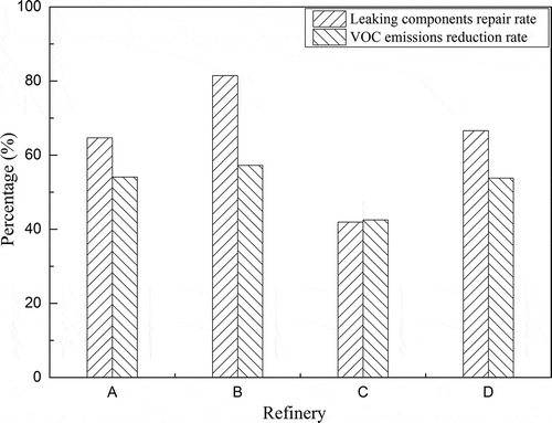
From and , through leaking components repair, the number of leaking components and VOC emissions have varying degrees of reduction. The leaking component repair rate and VOC emissions reduction rate from repairing leaking components range from 42% to 81% and from 42% to 57%, respectively. The VOC emissions reduction rate from repairing leaking components in these refineries is lower than that in the US refineries (63%) (EPA Citation2007). Among these refineries, B refinery has the highest repair rate and VOC emissions reduction rate, whereas D refinery has the lowest.
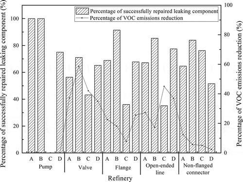
Comparing the repair results of different component categories (see ), it can be found that non-flanged connectors and open-ended lines have a high average repair efficiency, which successfully repaired about 66% of corresponding leaking components. It is useful and effective to eliminate the leakage from open-ended lines by adding caps, plugs, or double blocks. Most of the leakage from non-flanged connectors can be successfully repaired by tightening, rewinding or re-smearing the non-flanged connector, and tightening and replacing the gaskets. Valves have the lowest repair efficiency due to the frequent open and close operations and the high repair cost.
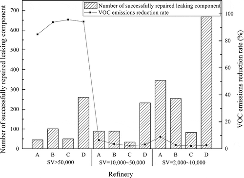
Analyzing the repair results of different initial leaking concentration ranges (see ), it can be found that repair leaking components with initial screening values above 50,000 ppmv have the highest control effectiveness, which resulted in up to 96% of VOC emissions reduction in the total VOC emissions reduction from repairing leaking components. For components that exceed 50,000 ppmv, 50% to 70% of the leaking components are valves and open-ended lines in these refineries. Based on the estimation method, when the concentrations of leaking valves and open-ended lines decrease from over 50,000 ppmv to below 2,000 ppmv, the VOC emissions could be reduced by at least 211 times and 170 times, respectively. Therefore, an effective way to reduce the VOC emissions is to locate and repair the leaking components with initial concentration over 50,000 ppmv, especially the valves and open-ended lines. In addition, a higher VOC emissions reduction from all components will occur after the effective repair of DOR components, which emit about 49% of the total VOC emissions from all components after repair.
LDAR implementation for different years
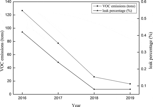
China has required all the refineries to conduct the LDAR program for the whole plant and submit the LDAR report every year. For a medium refinery, after the LDAR implementation for four consecutive years (i.e. from 2016 to 2019), the VOC emissions reduced by 87.6% and the leak percentage reduced by 80.9% (see ). This indicates that the application of the LDAR program in China refineries was effective.
Processing units
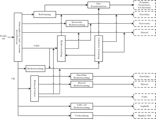
Different petroleum refineries have different types and quantities of processing units due to the different crude oil properties and desirable products. However, most refineries have major similarities in the main processing units and products, as shown in .
In this paper, six typical petroleum processing units in these four refineries, including crude (and vacuum) distillation unit (C(V)DU), catalytic cracking unit (CCU), continuous catalytic reforming (CCR), gasoline hydrotreating unit (GHT), diesel hydrotreating unit (DHT) and gas fractionation unit (GFU), were analyzed. The processing capacities of these units in four refineries are listed in .
Table 11. Capacity of processing units (104 tons/year).
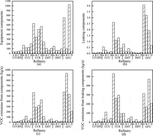
Considering the difference in the processing capacities of the units, the equipment numbers and VOC emissions of the six units were compared under the same processing capacity in this paper. The equipment components, leaking components, together with their VOC emissions of the six units are shown in .
It can be found that the GFU and CCR have a higher average quantity of components, leaking components and VOC emissions under the same processing capacity. And the other four units have the same levels. It is commonly known that volatile liquids have low boiling points. For alkanes and olefins, as the chain length increases, the boiling point increases. And the more branched the chain, the lower the boiling point tends to be. By analyzing the feedstock, products and reaction principles, these units process can produce liquefied petroleum gas and produce the pure propane, butane, propylene, and C4 mixture that all have high volatility. The CCR unit is applied to rearrange the structure of petroleum molecules and produce aromatics (mainly benzene, toluene, dimethylbenzene), which have lower boiling points than the feedstock and present higher volatility. Different characteristics of raw materials and products in GFU and CCR units promote the VOC emissions from leak equipment. Therefore, under the same capacity, the gas fractionation unit and continuous catalytic reforming should be paid more attention to control the leakage.
Economic effect
Costs
Since the LDAR program was first introduced and implemented in China’s refineries, the cost parameters listed below were only focused on the first time for LDAR implementation, including the setup, preparation, fieldwork stages. The cost of leakage repair was not included since the leak component repair and purchase work were accomplished by the refinery employees. This cost analysis was based on a Chinese state-owned refinery that has a medium processing capacity. And the instrument purchase costs have amortized over a period of five years. The details of the cost distribution are listed in . It can be seen that the labor costs of LDAR log establishment and component monitoring are the largest expense, which accounts for 49.8% of the total costs. The costs of each refinery may vary from the size, configuration, age, and condition.
Table 12. Costs distribution of LDAR program for a medium refinery.
Benefits
After implementing the LDAR program, there are many benefits, which can be broadly divided into direct economic benefits and indirect benefits. The reduction of VOC emissions can reduce pollutant discharge fees. The reduction of VOC emissions can reduce crude oil and hydrocarbon product loss and result in a decrease of the corresponding loss cost. The indirect benefits include health, safety, and environment (HSE) benefits. The VOC emissions reduction can result in enhancing the refinery process and worker safety and reducing the exposure of workers to the HAPs. It also can decrease the concentration of PM2.5 and ozone and improve air quality.
For a refinery with a processing capacity of 5 million tons per year, the refinery invested about 5.9 million yuan to implement the LDAR program for the first time in 2016. After the implementation, the VOC emissions reduced 92.53 tons. And according to the crude oil price released in the General Administration of Customs of China and the standard of charging the emission pollution fees published by the Ministry of Finance of China, the refinery saved about 0.4 million yuan in 2016. Similarly, the refinery invested 2.3 million yuan to implement the second round of LDAR in 2017. After that, the VOC emissions reduced 65.37 tons and the refinery saved about 0.3 million yuan in 2017.
Commonly, the costs of LDAR program implementation outweighed the benefits at the beginning stage. This is because the LDAR program is immature and a huge investment in fundamental research is required. Also, from the amount of investment, we can see that China is making efforts to improve the environment and investing huge finance in clean technologies which can improve the environment. And we believe the gap between cost and benefit will decrease.
Problems and suggestions
LDAR program is an effective technique for controlling and reducing fugitive emissions. And it is a long-term, systematic emission control program by routinely detecting and repairing equipment components. However, the LDAR program was first required and implemented in 2015 in China’s petroleum refineries and still in its infancy. There are several problems during LDAR application and implementation.
Leaking components repair
In general, after leak identification, refineries need to take measures to repair and eliminate the leakage for refineries by conducting simple methods or structural modifications. However, these repair methods are not considering the actual causes of leakage, which can not perform the comprehensive repair for the leaking components. In some cases, these components turn out to leak again. And over 70% of leaking valves and flanges require secondary repair. These phenomena indicate that after the success of the first attempt repair, the components still have the potential to leak. Moreover, the repair methods in these refineries are immature and the repair effect is not sustained.
For this issue, refineries should analyze the accurate causes of the leakage and make repair plans, such as replacing with high-sealing components, adjusting the process conditions and operating procedures, to control and eliminate the leakage. The regulations about leaking component repair still need to improve, which should focus on finding the root cause of leakage for different components and formulating effective recommended repair methods.
VOC emissions estimation
The correlation method for calculating the VOC emissions found to be low compared with the bagging method. The emission factors used in this paper were based on the Protocol for Equipment Leak Estimates, which was published by EPA in 1995. However, these emission factors were based on US refineries, which have significant differences in refining processes, crude oil and product properties with Chinese refineries. Therefore, it is difficult to accurately estimate VOC emissions using the EPA’s protocol.
In China, some researchers calculated VOC emissions through the inverse dispersion calculation method. And the estimated result was as the same order as the traditional emission factor method (Das Citation2009; Wei et al. Citation2016, Citation2018). On the other hand, China is making efforts to conduct the second national survey of pollution sources and to formulate scientific methods for calculating pollutant emissions, which suit China’s petroleum refineries.
LDAR program improvement
As we found, over 90% of VOC emissions are generated by 0.2%~0.4% leaking components. In China, the government and refinery have invested huge capital and employees for conducting the LDAR program and the whole result is not obvious. In addition, the LDAR program is costly and time-consuming.
In order to enhance the LDAR program and improve the LDAR program effectiveness, the Smart-LDAR, which using optical gas imaging technology to identify leaking components, is recommended to locate and repair the most significant leaking components more quickly and cost-effective than the traditional LDAR program. The Smart-LDAR has been adopted by many states, local agencies, and industries. (Epperson et al. Citation2007; Robinson et al. Citation2007; Safitri, Gao, and Mannan Citation2011; Sauger et al. Citation2013).
Conclusion
In this study, the LDAR data from four petroleum refineries were analyzed and the VOC emissions were estimated to evaluate the implementation effectiveness of LDAR program.
By analyzing the different categories of components in these refineries, we found that the valves, flanges, open-ended lines, and non-flanged connectors were the prevalent equipment components and leaking components. Valves, flanges, and non-flanged connectors were high VOCs emitting components. In these refineries, about 0.2% to 0.4% of equipment components were leaking components, and emitted up to 91.8% of the total VOC emissions from all components, especially leaking valves and open-ended lines.
After implementing the LDAR program, the VOC emissions from refinery components were reduced from 42% to 57% and 42% to 81% of leaking components were properly repaired, with the non-flanged connectors and open-ended lines have the highest average repair efficiency. And the VOC emissions can be further reduced by repairing DOR components.
Furthermore, it could result in different VOC emission reduction degrees by repairing the leaking components with different initial concentration ranges. For leaking components with concentration over 50,000 ppmv, it can achieve up to 96% VOC emissions reduction from all components, which was mainly generated by repairing leaking valves and open-ended lines. On the other hand, the gas fractionation unit and continuous catalytic reforming unit have a higher average number of components, leaking components and VOC emissions under the same processing capacity.
The results of this study showed that the implementation of LDAR program was feasible and effective to reduce VOC emissions from petroleum refineries. This study provides which kind of units and components should be closely monitored during the LDAR implementation and routine monitoring. The findings are helpful to develop specific regulations and plans for government and refineries and to enhance the effectiveness of LDAR program.
Supplemental Material
Download MS Word (17.6 KB)Acknowledgments
The work is supported by the National Science Foundation of Shandong Province, China (ZR201702150018) and the International Cooperation Program for Innovative Talents of the China Scholarship Council, China (liujinmei [2017] 7751). Thanks for the funding.
Disclosure statement
No potential conflict of interest was reported by the authors.
Supplementary material
Supplemental data for this article can be accessed on the publisher’s website.
Additional information
Funding
Notes on contributors
Jia Ke
Jia Ke is a Ph.D. student at the College of Chemical Engineering, China University of Petroleum (East China), in Shandong, People’s Republic of China.
Shi Li
Shi Li is an associate professor at College of Chemical Engineering, China University of Petroleum (East China), in Shandong, People’s Republic of China.
Dongfeng Zhao
Dongfeng Zhao is the corresponding author. He is professor at College of Chemical Engineering, China University of Petroleum (East China), Qingdao, Shandong 266580, People ’s Republic of China. He can be contacted at [email protected].
References
- Altieri, K. E., and A. Stone. 2016. Prospective air pollutant emissions inventory for the development and production of unconventional natural gas in the Karoo basin, South Africa. Atmos. Environ. 129:34–42. doi:10.1016/j.atmosenv.2016.01.021.
- An, J., B. Zhu, H. Wang, Y. Li, X. Lin, and H. Yang. 2014. Characteristics and source apportionment of VOCs measured in an industrial area of Nanjing, Yangtze River Delta, China. Atmos. Environ. 97:206–14. doi:10.1016/j.atmosenv.2014.08.021.
- CCME. 1993. Environmental code of practice for the measurement and control of fugitive VOC emissions from equipment leaks. Accessed January 18, 2020. https://www.ccme.ca/files/Resources/air/emissions/pn_1106_e.pdf.
- Chen, C. F., and J. J. Liang. 2013. Using a source-receptor approach to characterize the volatile organic compounds from control device exhaust in a science park. Environ Sci Pollut Res 20 (3):1526–36. doi:10.1007/s11356-012-1109-4.
- Das, S. K. 2009. Monitoring and inverse dispersion modeling to quantify VOCs from MSW landfill. Master’s dissertation, University of New Orleans.
- Ellis, H. M., and R. Lackaye. 1989. Estimating fugitive emissions of volatile compounds from equipment leaks. J. Air & Waste Manage. Assoc. 39 (12):1619–22. doi:10.1080/08940630.1989.10466656.
- EPA. 1978. Control of VOCs leaks from petroleum refinery equipment. Accessed January 18, 2020. https://www3.epa.gov/airquality/ctg_act/197806_voc_epa450_2-78-036_leaks_refineery_equipment.pdf.
- EPA. 1999. Proper monitoring essential to reducing fugitive emissions under LDAR. Accessed January 18, 2020. https://nepis.epa.gov/Exe/ZyPDF.cgi/500003SW.PDF?Dockey=500003SW.PDF.
- EPA. 2007. Leak detection and repair A best practices guide. Accessed January 18, 2020. https://www.epa.gov/sites/production/files/2014-02/documents/ldarguide.pdf.
- Epperson, D., M. Lev-On, H. Taback, J. Siegell, and K. Ritter. 2007. Equivalent leak definitions for smart LDAR (Leak Detection and Repair) when using optical imaging technology. J. Air & Waste Manage. Assoc. 57 (9):1050–60. doi:10.3155/1047-3289.57.9.1050.
- Guo, H., Z. H. Ling, K. Cheung, F. Jiang, D. W. Wang, I. J. Simpson, T. J. Wang, X. M. Wang, S. M. Saunders, and D. R. Blake. 2012. Characterization of photochemical pollution at different elevations in mountainous areas in Hong Kong. Atmos. Chem. Phys. Discuss. 12 (11):29025–67. doi:10.5194/acpd-12-29025-2012.
- Han, D., Z. Wang, J. Cheng, Q. Wang, X. Chen, and H. Wang. 2017. Volatile organic compounds (VOCs) during non-haze and haze days in Shanghai: Characterization and secondary organic aerosol (SOA) formation. Environ Sci Pollut Res 24 (22):18619–29. doi:10.1007/s11356-017-9433-3.
- Hao, J., K. He, L. Duan, J. Li, and L. Wang. 2007. Air pollution and its control in China. Front. Environ. Sci. Engin. China 1 (2):129–42. doi:10.1007/s11783-007-0024-2.
- Hong-Li, W., J. Sheng-Ao, L. Sheng-Rong, H. Qing-Yao, L. Li, T. Shi-Kang, H. Cheng, Q. Li-Ping, and C. Chang-Hong. 2017. Volatile organic compounds (VOCs) source profiles of on-road vehicle emissions in China. Sci. Total. Environ. 607-608:253–61. doi:10.1016/j.scitotenv.2017.07.001.
- Huang, R. J., Y. Zhang, C. Bozzetti, K. F. Ho, J. J. Cao, Y. Han, K. R. Daellenbach, J. G. Slowik, S. M. Platt, F. Canonaco, et al. 2014. High secondary aerosol contribution to particulate pollution during haze events in China. Nature 514 (7521):218–22. doi:10.1038/nature13774.
- Jaleh, B., M. Gandomi Rouzbahani, K. Abedi, S. Azizian, H. Ebrahimi, M. Nasrollahzadeh, and R. S. Varma. 2019. Photocatalytic decomposition of VOCs by AC–TiO2 and EG–TiO2 nanocomposites. Clean Technol. Environ. Policy 21 (6):1259–68. doi:10.1007/s10098-019-01702-3.
- Jecha, D., V. Brummer, P. Lestinsky, J. Martinec, and P. Stehlik. 2014. Effective abatement of VOC and CO from acrylic acid and related production waste gas by catalytic oxidation. Clean Technol. Environ. Policy 16 (7):1329–38. doi:10.1007/s10098-014-0750-7.
- Jia, C., X. Mao, T. Huang, X. Liang, Y. Wang, Y. Shen, W. Jiang, H. Wang, Z. Bai, M. Ma, et al. 2016. Non-methane hydrocarbons (NMHCs) and their contribution to ozone formation potential in a petrochemical industrialized city, Northwest China. Atmos. Res. 169:225–36. doi:10.1016/j.atmosres.2015.10.006.
- Khan, F. A., K. A. Al Sulaiti, and K. Bashir. 2015. “Qatargas LDAR fugitive VOC emissions program.” In Proceedings of the 4th International Gas Processing Symposium, edited by M. J. Al-Marri and F. T. Eljack, 301–08. Oxford: Elsevier.
- Kim, J., and B.-K. Lee. 2018. Enhanced photocatalytic decomposition of VOCs by visible-driven photocatalyst combined Cu-TiO2 and activated carbon fiber. Process. Saf. Environ. 119:164–71. doi:10.1016/j.psep.2018.07.026.
- Li, J., R. G. Uttarwar, and Y. Huang. 2013. CFD-based modeling and design for energy-efficient VOC emission reduction in surface coating systems. Clean Technol. Environ. Policy 15 (6):1023–32. doi:10.1007/s10098-013-0583-9.
- Liang, P., W. Jiang, L. Zhang, J. Wu, J. Zhang, and D. Yang. 2015. Experimental studies of removing typical VOCs by dielectric barrier discharge reactor of different sizes. Process. Saf. Environ. 94:380–84. doi:10.1016/j.psep.2014.09.003.
- Ling, Z. H., H. Guo, H. R. Cheng, and Y. F. Yu. 2011. Sources of ambient volatile organic compounds and their contributions to photochemical ozone formation at a site in the Pearl River Delta, southern China. Environ. Pollut. 159 (10):2310–19. doi:10.1016/j.envpol.2011.05.001.
- Liu, J., and J. Diamond. 2005. China’s environment in a globalizing world. Nature 435 (7046):1179–86. doi:10.1038/4351179a.
- Liu, M., Y. Huang, Z. Ma, Z. Jin, X. Liu, H. Wang, Y. Liu, J. Wang, M. Jantunen, J. Bi, et al. 2017. Spatial and temporal trends in the mortality burden of air pollution in China: 2004-2012. Environ. Int. 98:75–81. doi:10.1016/j.envint.2016.10.003.
- Martinez, A., S. Rathibandla, K. Jones, and J. Cabezas. 2007. Biofiltration of wastewater lift station emissions: Evaluation of VOC removal in the presence of H2S. Clean Technol. Environ. Policy 10 (1):81–87. doi:10.1007/s10098-007-0110-y.
- MEE. 2015. Guidelines for petroleum and refining industries leak detection and repair. Accessed January 18, 2020. http://www.mee.gov.cn/gkml/hbb/bgt/201511/W020151124546328688845.pdf.
- Mo, Z., M. Shao, S. Lu, H. Qu, M. Zhou, J. Sun, and B. Gou. 2015. Process-specific emission characteristics of volatile organic compounds (VOCs) from petrochemical facilities in the Yangtze River Delta, China. Sci. Total. Environ. 533:422–31. doi:10.1016/j.scitotenv.2015.06.089.
- Mustafa, M. F., Y. Liu, Z. Duan, H. Guo, S. Xu, H. Wang, and W. Lu. 2017. Volatile compounds emission and health risk assessment during composting of organic fraction of municipal solid waste. J. Hazard. Mater. 327:35–43. doi:10.1016/j.jhazmat.2016.11.046.
- Robinson, D. R., R. Luke-Boone, V. Aggarwal, B. Harris, E. Anderson, D. Ranum, T. J. Kulp, K. Armstrong, R. Sommers, T. G. McRae, et al. 2007. Refinery evaluation of optical imaging to locate fugitive emissions. J Air Waste Manag Assoc 57 (7):803–10. doi:10.3155/1047-3289.57.7.803.
- Saalberg, Y., and M. Wolff. 2016. VOC breath biomarkers in lung cancer. Clin. Chim. Acta 459:5–9. doi:10.1016/j.cca.2016.05.013.
- Safitri, A., X. Gao, and M. S. Mannan. 2011. Dispersion modeling approach for quantification of methane emission rates from natural gas fugitive leaks detected by infrared imaging technique. J. Loss. Prevent. Proc. 24 (2):138–45. doi:10.1016/j.jlp.2010.11.007.
- Sauger, E., S. Fily, H. Lejeune, and B. Thomas. 2013. Investigating the use of infrared cameras to detect VOCs. Sealing Technol. 2013 (4):8–12. doi:10.1016/s1350-4789(13)70142-9.
- Sunder Raman, R., and S. Kumar. 2016. First measurements of ambient aerosol over an ecologically sensitive zone in Central India: Relationships between PM2.5 mass, its optical properties, and meteorology. Sci. Total. Environ. 550:706–16. doi:10.1016/j.scitotenv.2016.01.092.
- Wang, B., M. Shao, S. H. Lu, B. Yuan, Y. Zhao, M. Wang, S. Q. Zhang, and D. Wu. 2010. Variation of ambient non-methane hydrocarbons in Beijing city in summer 2008. Atmos. Chem. Phys. 10 (13):5911–23. doi:10.5194/acp-10-5911-2010.
- Wang, Y., X. Ren, D. Ji, J. Zhang, J. Sun, and F. Wu. 2012. Characterization of volatile organic compounds in the urban area of Beijing from 2000 to 2007. J. Environ. Sci. 24 (1):95–101. doi:10.1016/s1001-0742(11)60732-8.
- Wei, W., S. Cheng, G. Li, G. Wang, and H. Wang. 2014. Characteristics of volatile organic compounds (VOCs) emitted from a petroleum refinery in Beijing, China. Atmos. Environ. 89:358–66. doi:10.1016/j.atmosenv.2014.01.038.
- Wei, W., Z. Lv, G. Yang, S. Cheng, Y. Li, and L. Wang. 2016. VOCs emission rate estimate for complicated industrial area source using an inverse-dispersion calculation method: A case study on a petroleum refinery in Northern China. Environ. Pollut. 218:681–88. doi:10.1016/j.envpol.2016.07.062.
- Wei, W., Y. Wang, G. Yang, L. Yue, and S. Cheng. 2018. Speciated VOCs emission estimate for a typical petrochemical manufacturing plant in China using inverse-dispersion calculation method. Environ. Monit. Assess 190 (8):451. doi:10.1007/s10661-018-6834-9.
- Zhang, G. 2016. Application and development trend of leak detection and repair (LDAR). Chinese. J. Environ. Eng. 10:4621–27.
- Zhang, S., J. You, C. Kennes, Z. Cheng, J. Ye, D. Chen, J. Chen, and L. Wang. 2018. Current advances of VOCs degradation by bioelectrochemical systems: A review. Chem. Eng. J. 334:2625–37. doi:10.1016/j.cej.2017.11.014.
- Zhang, Y. H., H. Su, L. J. Zhong, Y. F. Cheng, L. M. Zeng, X. S. Wang, Y. R. Xiang, J. L. Wang, D. F. Gao, and M. Shao. 2008. Regional ozone pollution and observation-based approach for analyzing ozone–precursor relationship during the PRIDE-PRD2004 campaign. Atmos. Environ. 42 (25):6203–18. doi:10.1016/j.atmosenv.2008.05.002.
- Zhao, M., T. Qiao, Z. Huang, M. Zhu, W. Xu, G. Xiu, J. Tao, and S. Lee. 2015. Comparison of ionic and carbonaceous compositions of PM2.5 in 2009 and 2012 in Shanghai, China. Sci. Total. Environ. 536:695–703. doi:10.1016/j.scitotenv.2015.07.100.
- Zhu, H., H. Wang, S. Jing, Y. Wang, T. Cheng, S. Tao, S. Lou, L. Qiao, L. Li, and J. Chen. 2018. Characteristics and sources of atmospheric volatile organic compounds (VOCs) along the mid-lower Yangtze River in China. Atmos. Environ. 190:232–40. doi:10.1016/j.atmosenv.2018.07.026.
- Zhuang, X., Y. Wang, H. He, J. Liu, X. Wang, T. Zhu, M. Ge, J. Zhou, G. Tang, and J. Ma. 2014. Haze insights and mitigation in China: An overview. J. Environ. Sci. 26 (1):2–12. doi:10.1016/s1001-0742(13)60376-9.

