ABSTRACT
This study presents the heavy metal results obtained during Finnish interlaboratory comparison (ILC) measurements made during 2019. The aim of this measurement campaign was to verify the skills of accredited emission measurement teams and also to evaluate the challenges that stack testing teams face in the future when emission levels decrease. ILCs have been organized in Finland since the 1970s. ILCs provide an important platform for stack testing teams so that they can verify their measurement skills and also for the dissemination of knowledge. The knowledge about the measurement standards and their requirements has improved among stack testing teams during past years in Finland. As emission levels get lower, they still need to pay more attention to some quality assurance procedures, e.g. to method and field blanks. Based on the observations of this ILC for heavy metals it can be noted that the challenges that stack testing teams face are related to the fact that no guidance is given in the standard reference methods EN 13211 and EN 14385 for example on the calculation of measurement uncertainties and how results below limit of quantification should be taken into account. These reference methods were suitable for their purpose at the time they were validated. However, emission levels are now more stringent and it is challenging to measure them with acceptable uncertainty criteria. As a consequence, there is a clear need for harmonized approaches in Europe for consistent implementation of standards and regulations. Key issues where guidance should be provided include realistic measurement uncertainties at low concentration levels, reporting low concentrations and guidance on how measurement uncertainties should be taken into account when the results are used for compliance assessment. The overall aim is to ensure that even with low emission levels, the emission measurement results would be transparent and robust throughout the EU.
Implications: Interlaboratory comparison measurements between stack testing teams are the most important tool to verify the quality of the measurements. Participation in an appropriate ILC is often mandatory to successfully achieve accreditation under ISO/IEC 17025. Such campaigns also provide an efficient platform for dissemination of knowledge. In addition, ILCs can be used to clarify the challenges that teams nowadays face when measuring low emission levels, thus creating important information for the revision work of standards.
Introduction
The European Industrial Emissions Directive, IED, 2010/75/EU (European Commission, Citation2010), later referred to as IED, sets out emission limit values (ELV) for example for large combustion plants as well as for waste incineration processes.
For heavy metals (As, Cd, Cr, Co, Cu, Mn, Ni, Pb, Sb, TI, V, and Hg), one measurement at least every 3 months shall be carried out for the first 12 months of operation of a waste incineration unit and after this time period at least two measurements per year. It is also specified that if heavy metal emissions are under all conditions below 50% of their ELV, then the competent authority may decide to require only one measurement every 2 years for heavy metals.
In addition to IED, sector-specific Best Available Techniques reference documents (BREFs) are produced in Europe and used for defining operating permits for industry. The “BAT conclusions” is a document containing the parts of a BREF document laying down the conclusions on best available techniques, and BAT conclusions are binding. Permits given to industrial activities shall be based on so-called BAT-Associated Emission Levels (BAT-AEL).
In many BREF documents, new BAT conclusions pose even lower emission limits for many pollutants. In , a comparison between ELVs given in IED and BAT-AEL values given in WI BREF (EC Citation2019) is given.
Table 1. Comparison of IED-ELVs with WI-BREF BAT-AEL values (heavy metals).
Member countries can decide themselves whether they use the upper or lower limit BAT-AEL values when setting the permits for industrial operations. The local competent authority is at liberty to set an emission limit anywhere in this range (or even below the minimum) but may not set a limit value that is above the range.
According to IED, sampling and analysis of all polluting substances shall be carried out according to EN-standards. EN 13211 (CEN Citation2001) is a European Standard Reference method for the measurement of mercury, Hg, in emissions and this method has been validated to measure total mercury levels from 0.001 mg/m3 to 0.5 mg/m3 (= 1 to 500 µg/m3). This standard is based on a wet-chemical method. The sample is extracted from the stack using a heated probe. Particulates are collected on a filter, whereafter the sample gas is passed through absorption bottles containing appropriate absorption solution to collect gaseous phase mercury. Two absorption solutions can be used, either 2% KMnO4/10% H2SO4 (absorption solution I) or 4% K2Cr2O7/20% HNO3 (absorption solution II). After the sampling, the filter and absorption solutions are taken to the analytical laboratory to be analyzed. The result is given as the sum of the gaseous and particulate phases, i.e. as total mercury.
EN 14385 (CEN Citation2004) is a European Standard Reference method for the measurement of As+Cr+Co+Cu+Mn+Ni+Pb+Sb+V. This method has been validated to each of the specific elements in the concentration range of 0.005 mg/m3 to 0.5 mg/m3 and it is based on a wet-chemical method, meaning collection of particulate matter on a filter and collection of gaseous phase in an absorption solution. According to EN 14385, the absorption solution is 4.65% HNO3/1.7% H2O2. The final result is expressed as the total mass concentration for each specific element and no distinction is made between gaseous and particulate phase.
Both of the above-mentioned standards are written and validated during the 1990s, at a time when emission levels were higher. According to CEN rules, EN standards are revised at regular intervals and at this review the members can vote to either revise, reconfirm (no changes) or withdraw the standard. Both of these standards (EN 13211 and EN 14385) are currently revised. In the following chapter some topics that need guidance or clarification in these standards at the moment are described.
Observations from EN 13211 and EN 14385
In many CEN standards the maximum relative expanded uncertainty for the method is given. For example, for particulates it is stated in EN 13284–1 that the user of this SRM method must demonstrate that the expanded uncertainty does not exceed 20% of the emission limit value specified by the authorities. (SRM refers to Standard Reference Method and, according to EN 15259 (CEN Citation2008), SRM is a “reference method prescribed by European or national legislation”). This expanded uncertainty is calculated on a dry basis and before correction to the O2 reference concentration, and it is calculated by establishing an uncertainty budget.
However, in the existing EN standards for mercury (EN 13211) and for heavy metals (EN 14385) this criterion for expanded measurement uncertainty does not exist. This means that there are several ways of calculating the measurement uncertainties and there can be large deviations between different stack testing teams and countries. In addition, there is no general rule concerning how to use measurement uncertainty; this is decided independently by each member state. When the result is used for compliance measurement, measurement uncertainty can be subtracted from the measured value, it can be neglected totally, or in some cases it is added to the measured value.
Furthermore, in the above-mentioned standards, no guidance is given about how the limit of detection (LOD) or limit of quantification (LOQ) should be determined. In the European standard EN 14793 (CEN, Citation2017b), the following definitions for LOD and LOQ are given:
-Limit of detection means the smallest measurand concentration which can be detected, but not quantified, in the experimental conditions described for the method;
-Limit of quantification means the smallest measurand concentration which can be quantified in the experimental conditions described for the method.
However, in EN 13211 and EN 14385 no guidance is given about which term should be used, LOD or LOQ and there are no instructions for how to sum up the values which are below LOQ or LOD. This will significantly affect the results since it is very common that the concentrations for many components are nowadays below the analytical thresholds.
Therefore many European countries have provided their own national guidance on how to perform these calculations. A few examples of different calculations are given in .
Table 2. Examples of different rules for summation for the results which are below either LOD or LOQ.
For example, in the PCDD/F standard EN 1948–3 (CEN Citation2006), it is instructed to report two values, one in which all results below LOQ are taken into account as zero and one in which all values below LOQ are taken into account as full values.
Some analytical procedures instruct taking LOQ value as half of its value.
In , an example is given of the results which are achieved when using these different calculation methods:
-Method A: Values below LOQ are taken into account in the sum as their full value
-Method B: Values below LOQ are taken into account in the sum as half their value (½ LOQ)
-Method C: Values below LOQ are taken into account in the sum as zero.
Table 3. Examples of the summation of concentrations which are below LOQ (marked with “<”).
Note! “<” is not marked in the calculated sum result.
When these concentrations calculated with methods A, B, and C are used to calculate the sum of pollutants required by IED, the results are as shown in .
Table 4. Final results calculated with different methods (A, B, and C) based on the measured concentrations given in and compared with BAT-AEL ranges.
As it can be seen from , for example, the final results calculated for Hg with Methods A and B exceed the lowest BAT-AEL limit value set for mercury, 1 µg/m3 while the result calculated using method C is below this limit value. Thus, the summation rules for LOQ values have a distinct effect on the final result.
It is mentioned in the Reference Document on Monitoring, ROM (EC Citation2018), that LOD and LOQ depend strongly on the performance of the laboratory and possible modifications or adaptations to specific circumstances. It is recommended in ROM that, e.g., for periodic measurements, the sampling time can be adapted and/or the analytical method can be chosen to reach an acceptable LOQ.
However, it must be noted that for practical reasons it is not always possible to extend the sampling time. In addition, if the measured flue gas contains lot of moisture, extending the sampling time does not help to obtain lower LOQ values, on the contrary. The volume of absorption solution in the first absorption bottle will be increased due to the condensed water, thus, increasing LOQ values.
To conclude the existing situation:
-the requirement for maximum expanded measurement uncertainty does not exist in SRM standards for heavy metals and mercury and there is no general rule concerning how this measurement uncertainty should be taken into account, this is decided individually by each member state
-there are no harmonized rules about how to sum up results which are below LOD or LOQ or which definition should be applied, LOD or LOQ.
As a consequence, due to this lack of guidance there can be remarkable variations in the emission results that European countries report into inventories, such as E-PRTR (European Pollutant and Transport Register).
Finnish interlaboratory comparison measurement procedures
In Finland, VTT Technical Research Center (later referred to as VTT) has organized several interlaboratory comparison (ILC) measurement campaigns for Finnish stack testing teams. The first measurements were organized already in the 1970s and the frequency of these campaigns has typically been 4–5 years. The objective in these measurements has mainly been to verify the skills of Finnish stack testing teams but also to share information about new procedures and requirements, so these occasions have also acted as an important platform for the dissemination of knowledge and training.
Finnish ILCs have been organized in real stacks. There are currently different approaches available for ILCs in Europe. Some countries use synthetic gas mixtures which are made by spiking different gas compositions into the test bench facility (Coleman et al. Citation2019, Citation2015; Cordes, Stoffels, and Wildanger Citation2015), whereas others use gas matrices which are produced, for example, with boilers (Ineris ILC Schemes). All these approaches have their pros and cons. For example, when the gas matrix is prepared with spiking, the metrological value with known uncertainty can be used as the assigned value. When the measurements are performed from real stack gas matrices, then the metrological value cannot usually be used; instead a consensus value between participants is used. However, when using real stacks, all possible interfering factors are included in the evaluation, meaning, for example, moisture of the flue gas, temperature, possible interfering components, difficult measurement circumstances (e.g. hot/cold environmental conditions). Therefore, with real stacks, the “real world” challenges which stack testing teams face during their measurements will be realized. Therefore Finland has chosen to organize ILCs at real stacks.
The first ILCs for heavy metals were organized in Finland in 2014. During these measurements all stack testing teams stated that they performed the measurements according to the instructions given in reference standards (EN 14385 and EN 13211). However, it was observed that the actual measurement practices of some teams differed considerably from the standard procedures. In addition, stack testing teams used different ways to sum up the results which were below the limit of quantification. Some teams took these values into account as full values, whereas others considered them as zero values.
After the ILC organized in 2014, a national guidance concerning how to sum up heavy metal concentrations values which are below LOQ was produced in Finland (Pellikka, Kajolinna, and Antson Citation2017). This guidance is shown in in this article.
This paper focuses on the heavy metal results of the measurement campaign from the year 2019 and their observations, as well as on the comparison of chemical analysis of heavy metals. Based on the observations made from the results, challenges that stack testing teams face while measuring low concentrations were identified and recommendations for the development of measurement practices and standards were given, as well as for the quality assurance procedures that stack testing teams should pay more attention to.
Interlaboratory comparison measurements for heavy metals at a waste-to-energy plant in 2019
Experimental
In the spring of 2019, VTT organized interlaboratory comparison measurements for Finnish accredited stack testing teams.
Measurements were carried out at a waste-to-energy plant located in southern Finland. This plant combusts municipal waste in a grid furnace, with a fuel capacity of 55 MW and it is equipped with the following abatement systems:
-electrostatic precipitator and fabric filter
-spray dryers
-scrubbers for HCl and SO2.
During this measurement campaign all the pollutants required to be measured from waste incineration plants according to IED were measured (CO, SO2, NOx, TVOC (total volatile organic carbon), HCl, HF, heavy metals, mercury, and PCDD/F).
The emission limit values (ELVs) for heavy metals and mercury of this waste-to-energy plant are presented in .
Table 5. Average emission limit values for heavy metals at a waste-to-energy plant, values given at NTP (NTP specified in Europe as 273.15 K and 101.3 kPa).
Emission measurements were performed on a measurement platform located at a height of 20 meters. Flue gas temperature was typically around 130°C and the moisture content of the flue gas about 20– 22%. Flue gas composition was approximately 9% O2, 5 mg/m3 SO2 and 200 mg/m3 NOx. The measurement place was located in a well-protected room where the environmental conditions were stable throughout the measurement campaign, with a temperature around +20°C.
Eight stack testing teams (presented here as laboratories A, B, C, D, E, F, G, and H) took part in the heavy metal measurements and four of them had accreditation according to ISO/IEC 17025 for these measurements (laboratories A, C, E, and F).
Homogeneity of the flue gas was tested before the measurements according to the principles given in EN 15259 (CEN Citation2008). Flue gas is assumed to be homogeneous for an individual measurand if the actual value varies only over time but not over the measurement plane.
For the tests of homogeneity, two probes were installed in the flue channel, one for the reference measurement of O2 at a fixed point in the measurement section and the other for the grid measurement of O2. Grid measurement was performed and at the same time measurements at the fixed point and O2 results were recorded. Standard deviation of the grid measurements (sgrid) was 0.18 and standard deviation of the reference measurements (sref) was 0.18. The calculation for homogeneity was performed with these values and it was ascertained that the flue gas was homogeneous at the measurement plane. According to the standard EN 15259 the criterion for homogeneity is sgrid ≤ sref and this criterion was fulfilled.
According to the standards EN 13211 and EN 14385, heavy metal measurements shall be performed isokinetically with grid measurements throughout the stack. However, this is not possible when ILCs measurements are performed since it is not possible to move the probes at the same time in the stack. Therefore, for practical reasons, the measurements for heavy metals were performed using only one measurement point in the stack. All teams inserted their probes to the same depth into the stack.
Results and discussion
Due to the limited number of suitable measurement ports, only four teams were able to measure at the same time, and therefore measurements for heavy metals were carried out in two parts, on 8.5.2019 and on 15.5.2019. Sampling duration was 3 hours 4 minutes on 8.5.2019 and 2 hours 5 minutes on 15.5.2019, thus fulfilling the criteria set for the sampling duration in IED.
The criterion for the isokinetic ratio of sampling is 0.95–1.15. Isokinetic ratios given by the stack testing teams were:
-team A 0.76*
-team B 1.07
-team C 1.10
-team D 1.08
-team E 1.04
-team F 1.01
-team G 1.10
-team H not given
*team A stated that due to the high amount of moisture in the flue gas, they were not able to keep the sampling rate isokinetic
According to the standard EN 13211, two absorption liquids can be used for the sampling of mercury:
-2% KMnO4/10% H2SO4 (absorption solution I): used by stack testing teams B and C in these measurements
-4% K2Cr2O7/20% HNO3 (absorption solution II): used by stack testing teams A, D, E, F and H in these measurements.
Stack testing teams sent their samples to be analyzed to an external analytical laboratory. One emission measurement team (G) used their own internal analytical laboratory and their ICP-OES instrument for the analysis of heavy metals, and since they do not offer commercial analytical services, their LOQ values are not given in this article. Team G is in-house laboratory of non-ferrous metal industrial plant and they perform heavy metal sampling only for their own processes which have typically higher concentrations than waste-to-energy plants.
Chemical analysis was performed at three commercial analytical laboratories (named here as 1, 2, and 3):
-analytical laboratory 1: accreditation according to ISO/IEC 17025 for all components (As, Cd, Cr, Co, Cu, Mn, Ni, Pb, Sb, TI and V, as well as Hg) both for the analysis of absorption solution and filter. Heavy metals by ICP-MS and Hg by AFS
-analytical laboratory 2: accreditation according to ISO/IEC 17025 for the analysis of absorption solution and filter for components: As, Cd, Cr, Co, Cu, Mn, Ni, Pb, Sb, TI and V. Accreditation for the analysis of absorption solution for Hg, not for the analysis of Hg on the filter. Heavy metals by ICP-MS and Hg by AFS
-analytical laboratory 3: accreditation according to ISO/IEC 17025 for the analysis of absorption solution and filter for components: As, Cd, Cr, Co, Cu, Mn, Ni, Pb, Sb, TI and V. Accreditation for the analysis of absorption solution for Hg, not for the analysis of Hg on the filter. Heavy metals by ICP-MS and Hg by AFS.
Analytical laboratories reported their limits of quantifications (LOQ) for the analysis of absorption solution and they are shown in . Note! It was not possible to make similar comparison for LOQs for the analysis of filters since analytical laboratories reported them in different units.
Table 6. Limits of quantification (LOQ) given by analytical laboratories (µg/l) for the absorption solution.
Stack testing teams used the following analytical laboratories in their chemical analysis:
-stack testing team A: analytical laboratory no.2
-stack testing team B: analytical laboratory no.1
-stack testing team C: analytical laboratory no.1, Hg analysis at analytical laboratory no.2
-stack testing team D: analytical laboratory no.2
-stack testing team E: analytical laboratory no.1
-stack testing team F: analytical laboratory no.1
-stack testing team H: analytical laboratory no. 3.
Measured results are shown in (Hg, sum of Cd and Tl, sum of As, Cr, Co, Cu, Mn, Ni, Pb, Sb, and V). NTP refers to Normal Temperature and Pressure which is in Europe specified as 273.15 K and 101.3 kPa. The bars shown in the figures represent the measurement uncertainties which the stack testing teams gave in their reports. If measured values were below the limit of quantification (LOQ), then the stack testing teams did not determine measurement uncertainties for these values.
Figure 1. Hg-concentration results measured by stack testing teams A, B, C and D, 8.5.2019, waste-to-energy plant, Finland.
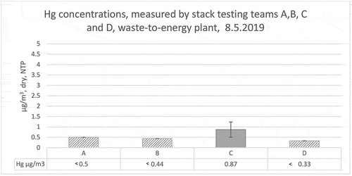
Figure 2. Hg-concentration results measured by stack testing teams E (result below LOQ), F and H (* team H only had results from gaseous phase), 15.5.2019, waste-to-energy plant, Finland.
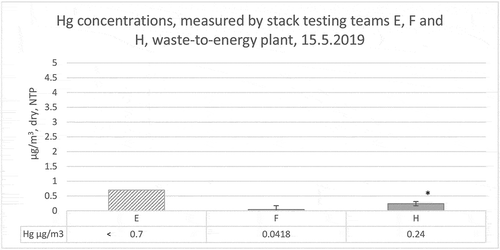
Figure 3. Sum of Cd and Tl concentrations measured by stack testing teams A, B, C and D, 8.5.2019, waste-to-energy plant, Finland.
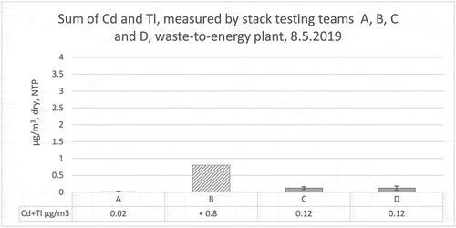
Figure 4. Sum of Cd and Tl concentrations measured by stack testing team E (below LOQ), F, G (below LOQ) and H (* stack testing team H only had results from gaseous phase), 15.5.2019, waste-to-energy plant, Finland.
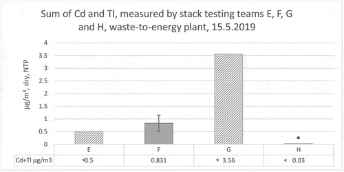
Figure 5. Sum of heavy metal concentrations (As, Cr, Co, Cu, Mn, Ni, Pb, Sb and V) measured by stack testing teams A, B, C and D, 8.5.2019, waste-to-energy plant, Finland.
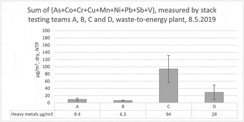
Figure 6. Sum of heavy metal concentrations (As, Cr, Co, Cu, Mn, Ni, Pb, Sb and V) measured by stack testing teams E, F, G (below LOQ) and H (* stack testing team H had only results from gaseous phase, result below LOQ), 15.5.2019, waste-to-energy plant, Finland.
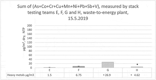
All stack testing teams used the guidance that was given in Finland in 2017 for summation of values which were below LOQ, shown in (Pellikka, Kajolinna, and Antson Citation2017).
The analytical laboratory which analyzed the samples of stack testing team H made an error in their analysis procedure and therefore, the results of stack testing team H contain information only about the gaseous phase.
Hg results of laboratories A, B, and D were below their limit of quantification, LOQ.
The sum results for Cd and Tl from stack testing teams B, E, G, and H were below their limit of quantification, LOQ.
The results for sum of heavy metals () of stack testing teams G and H were below their limit of quantification, LOQ.
Relative measurement uncertainties that stack testing teams reported are shown in .
Table 7. Measurement uncertainties reported by stack testing teams (A-H) for heavy metals, Cd + Tl and Hg, ILC, 2019, Finland.
As can be seen from , there were significant deviations in the reported measurement uncertainties. The procedures with which stack testing teams calculated and reported their measurement uncertainties varied considerably, a few examples are given below:
-some teams reported them separately for each component and for the sum of the components
-some reported them only for the sum of the components
-some teams reported them both for gaseous and particulate phase concentrations, as well as the sum of the components
-some teams did not report the confidence level that they had used (measurement uncertainties are typically reported as 95 % confidence level, and this should be specified in the report).
Based on these observations, it can be stated that there is a clear need to write instructions in the relevant standards (EN 13211 and EN 14385) about how measurement uncertainties should be calculated.
There were variations in the measured concentrations, however, all measured results were well below the ELVs set for this waste-to-energy plant. It should be mentioned that during the validation process for EN 14385 it has been also noticed that “in the gaseous phase most of the elements cannot be determined quantitatively in the absorption solutions”.
Stack testing teams A, B, C, D, E, and H used borosilicate probes while team F used probe made from titanium and team G probe made from PTFE. All these materials are allowed to be used by EN 13211 and EN 14385.
All stack testing teams performed field blanks according to the instructions given in EN 13211 and EN 14385. The criterion set for field blanks in EN 13211 and EN 14385 is that field blank must be <10% of ELV and all field blanks fulfilled this criterion.
However, some stack testing teams reported elevated concentrations for some components in their field blank samples. For example, stack testing team C had higher levels for some components (e.g. for Cu and Pb). They have studied the quality of the ion-exchanged water that they used to dilute the absorption liquids but this was not the reason for these elevated levels, and the reasons were not ascertained. Also, stack testing team B reported higher levels in their field blank for Cr, Cd, Cu, Pb and Ni, and this team has evaluated that the reason for this is possible contamination during sampling or during the cleaning of the glassware before the measurement campaign.
It must be emphasized that despite these teams had elevated levels for some heavy metals in their field blanks, their field blanks fulfilled the criterion set for it. When the ELVs get lower, it might be that this criterion is no longer fulfilled. So, stack testing teams shall pay more attention, for example, to the cleaning procedures of their glassware and to their sampling procedures in order to avoid any contamination. And in addition, also plants must keep the measurement places clean enough, so that there is minimal risk for contamination while handling the measurement equipment at the site.
In the future stack testing teams must also pay more attention to the method blank which consists of chemical and filter blanks. According to the definition given in EN 14385, “chemical blank is a solution used to check the purity of the chemicals employed by the laboratory”. Filter blank is a blank from the filter which has been taken from the same batch as the sample filters. The filter blank gives the blank values for the filter and treatment only. The method blank can be subtracted from the measured values if considered necessary. It should also be noted that a field blank is not the same than as a method blank.
During this measurement campaign some stack testing teams did not analyze above-mentioned method blanks at all. However, when emission limit values become even more stringent, the reagent purity and the background concentration at the filter material will play an increasingly significant role. Therefore, the measurer should choose such reagents and filters that have background concentrations which are low enough, and if required these background values should be subtracted from the measured concentrations.
All teams performed leak tests for their sampling lines before the measurements. It is recommended that leaks are checked also during actual measurement with the measurement of O2 at the end of the sampling line and comparing this value with the oxygen level found in the stack. Teams B, C, D, and E measured O2 at the end of line, thus ensuring that there were no leaks in their sampling lines during sampling.
According to EN 13211 and EN 14385, the absorption efficiency shall be determined during the measurement campaign. In EN 14385, it is mentioned that “If the element mass concentration of the third absorber is more than 10% of the total concentration in the sampled gas for one or more elements than the overall result shall be rejected”. Stack testing teams (not all) reported their absorption efficiencies during this ILC and in many cases the absorption efficiencies did not fulfill this criterion. One possible reason was the high moisture content in the flue gas (about 20– 22%) which diluted the content of the first absorption bottle so that the concentrations were often below limit of quantification. As a consequence, the calculations for absorption efficiency were not anymore reasonable.
In the United Kingdom, Environment Agency (EA) has published Method Implementation Document for BS EN 14385 (Environment Agency for England Citation2018). In this document it is mentioned: “However, for each group the requirement to pass the absorber efficiency check shall not apply:
-to individual metal element(s), where the individual mass of the element in the final result is less than 1% of the result for the total mass of metals in the group; or
-if the total combined result for the metals in the group is less than 30% of the ELV”.
During this Finnish ILC all measured concentrations were less than 30% of the ELV. So, if this rule would be applied in Finland, the requirements to pass this check would not be applied in this case.
In EN 14385 it is also mentioned that “For the main stream arrangement cooling of the absorbers to a temperature below 30°C can be useful to avoid excessive evaporation from the first absorption bottle”. This is not a mandatory requirement from the standard, however, it is strongly recommended to have absorption bottles and silicagel bottle in ice-bath in order to have better absorption efficiency and also in order to have efficient drying of the gas, especially when using dry gas meters. All Finnish stack testing teams used dry gas meters and most of the stack testing teams had ice-baths for their absorption bottles but not all teams. Stack testing teams must pay attention to this procedure in the future.
Heavy metal distribution to the gaseous and particulate phase
In this section heavy metal distributions to the gaseous and particulate phases are presented. Most of the heavy metal results were below the limit of quantification, as was described in the previous section. Due to the summation guidance which the stack testing teams used, the concentrations shown in this section may differ from those in the previous section. Stack testing teams G and H are not included in this section for the reasons mentioned in section 4.2.
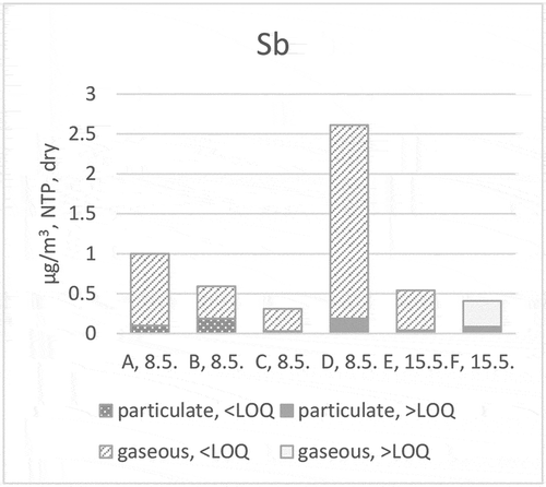
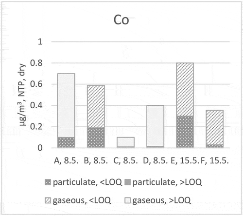
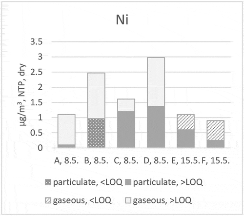
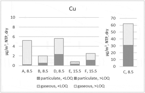
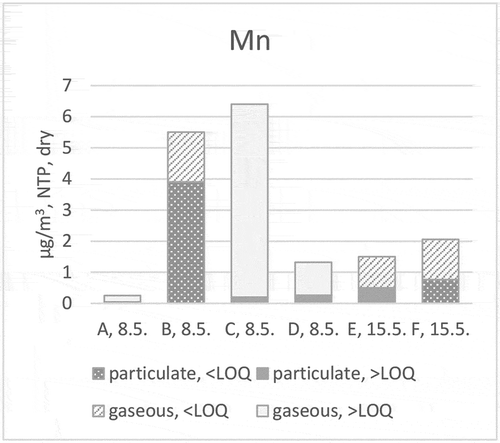
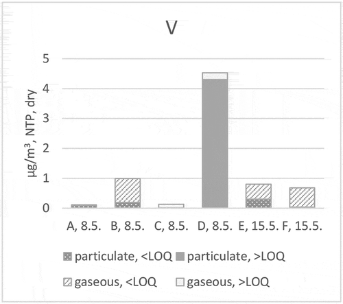
In to 18 the results below LOQ are plotted as pattern fill and the results which are above LOQ are shown as solid fill.
Figure 7. Hg distribution (stack testing teams A, B, C, D, E and F) to particulate and gaseous phases at ILC in 2019.
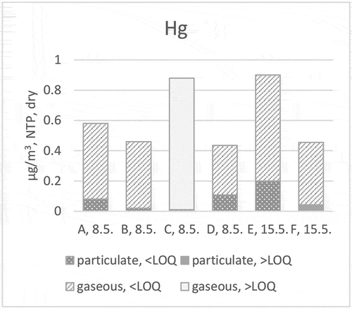
and present the particulate and gaseous distribution of mercury (Hg) () and antimony (Sb) () measurements. In the case of mercury, the gaseous part of stack testing team C and the particulate results of stack testing team F were above the LOQ. In the case of antimony, the gaseous result of stack testing team F and particulate results of stack testing teams D, E and F were above LOQ.
Figure 8. Sb distribution (stack testing teams A, B, C, D, E and F) to particulate and gaseous phases at ILC in 2019.
and present the particulate and gaseous distribution of cadmium (Cd) () and thallium (Tl) () measurements. In case of cadmium, the particulate results of stack testing teams A and B and the gaseous results of stack testing teams B and E were below LOQ. For thallium, the particulate result of stack testing team C and the gaseous result of stack testing team D were above the LOQ.
Figure 9. Cd distribution (stack testing teams A, B, C, D, E and F) to particulate and gaseous phases at ILC in 2019.
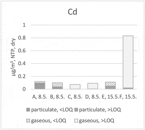
Figure 10. Tl distribution (stack testing teams A, B, C, D, E and F) to particulate and gaseous phases at ILC in 2019.
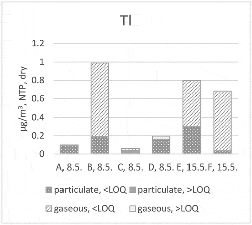
and present the particulate and gaseous distribution of arsenic (As) () and cobalt (Co) () measurements. For arsenic, the gaseous result of stack testing team C and the particulate results of stack testing teams C, D, and F were above LOQ. For cobalt, the gaseous result of stack testing teams A, C, and D, as well as particulate results of stack testing teams C and D were above LOQ.
Figure 11. As distribution (stack testing teams A, B, C, D, E and F) to particulate and gaseous phases at ILC in 2019.
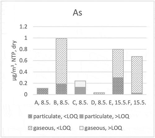
Figure 12. Co distribution (stack testing teams A, B, C, D, E and F) to particulate and gaseous phases at ILC in 2019.
and present the particulate and gaseous distribution of chrome (Cr) () and nickel (Ni) () measurements. For chrome, the gaseous results of stack testing teams E and F were below LOQ. For nickel, the gaseous result of stack testing teams E and F, as well as the particulate result of stack testing team B were below LOQ.
Figure 13. Cr distribution (stack testing teams A, B, C, D, E and F) to particulate and gaseous phases at ILC in 2019.
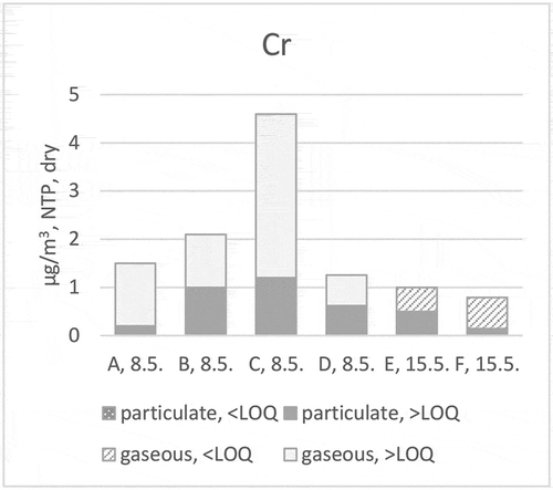
Figure 14. Ni distribution (stack testing teams A, B, C, D, E and F) to particulate and gaseous phases at ILC in 2019.
presents the particulate and gaseous distribution of copper (Cu) measurements. The particulate result of stack testing team A was below LOQ as well as gaseous result of stack testing team E.
Figure 15. Cu distribution (stack testing teams A, B, C, D, E and F) to particulate and gaseous phases at ILC in 2019.
and present the particulate and gaseous distribution of lead (Pb) () and manganese (Mn) () measurements. For lead, only the particulate result of stack testing team A was below the LOQ. For manganese, the particulate results of stack testing teams B and F were below the LOQ, as well as the gaseous results of stack testing teams B, E, and F. After the ILC, stack testing team C has studied the quality of the ion-exchanged water that they used to dilute the absorption liquids but this was not the reason for higher levels (such as Pb and Cu), and the reasons for these elevated levels were not ascertained.
Figure 16. Pb distribution (stack testing teams A, B, C, D, E and F) to particulate and gaseous phases at ILC in 2019.
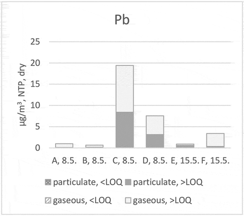
Figure 17. Mn distribution (stack testing teams A, B, C, D, E and F) to particulate and gaseous phases at ILC in 2019.
presents the particulate and gaseous distribution of vanadium (V) measurements. The particulate and gaseous results of stack testing teams C and D were above the LOQ.
Figure 18. V distributions (stack testing teams A, B, C, D, E and F) to particulate and gaseous phases at ILC in 2019.
The distributions to particulate and gaseous phase are given for each stack testing team also in and below.
Table 8. Particulate phase (heavy metals) reported by stack testing teams A, B, C, D, E, and F, ILC, May 2019, Finland.
Table 9. Gaseous phase (heavy metals) reported by stack testing teams A, B, C, D, E, and F, ILC, May 2019, Finland.
As can be seen from this study of particulate and gaseous phase distribution, many results were below LOQ.
Stack testing teams A and D used the same analytical laboratory for their chemical analysis of heavy metals and stack testing teams B, C, E, and F used another analytical laboratory. Stack testing team C used same analytical laboratory for the analysis of mercury like teams A and D. As it can be seen from Figures from 7 to 18 and from and , there are deviations between the distributions to particulate and gaseous phases, as well as on the final concentrations and on the reported values for LOQ. With these limited data we cannot, however, draw unambiguous conclusions of the reasons. The reasons for these deviations could originate for example from differences in the volume of the sampled gas, amount of absorption solution in impinger bottles, method blanks or contamination during sampling or during chemical analysis.
Comparison of chemical analyses for heavy metals
As is often the case, sampling of emissions plays an important role. However, the quality and accuracy of chemical analysis should not be ignored, since it will be even more important in the future in order to obtain reliable results from these measurements. Therefore, it was decided to carry out a blind comparison between analytical laboratories during the ILC organized in year 2019 in order to verify the quality of their results.
Two heavy metal and mercury samples were taken by VTT during the measurement campaign at waste-to-energy plant, the first one on 8.5.2019 and the second on 9.5.2019. These samples were split and sent to different analytical laboratories to be analyzed. The results are shown in and .
Table 10. Comparison of chemical analysis, sample taken on 8.5.2019, waste-to-energy plant.
Table 11. Comparison of chemical analysis, sample taken on 9.5.2019, waste-to-energy plant.
Analytical laboratory A is the laboratory no. 2 shown in and analytical laboratory E is the laboratory no. 1 shown in . As it can be seen from chapter 4.2, analytical laboratory A was used by stack testing teams A, C (Hg) and D to analyze their samples and analytical laboratory E was used by stack testing teams B, C (heavy metals), E and F to analyze their samples. Other analytical laboratories shown in and (B, C, D, and F) were not used by stack testing teams to analyze their samples during ILC.
All the other analytical laboratories except laboratory B have accreditation for their analyses according to ISO/IEC 17025. Laboratories B and C did not analyze mercury.
As can be seen from –, the measured concentrations did not have significant deviations from each other. What should be noted, however, is that there were significant deviations in the LOQ values. For example, LOQ for laboratory A for arsenic is <0.02 µg/l, whereas for laboratory E is <1 µg/l. When emissions become lower in the future, these values will have increasing significance.
Conclusion
VTT has organized ILCs in Finland since the 1970s. ILCs provide an important platform for stack testing teams so that they can verify their measurement skills and also for the dissemination of knowledge.
Latest ILC for heavy metals was organized in Finland during 2019. There were variations in the measured concentrations between stack testing teams, however, all measured results were well below the ELVs set for this waste-to-energy plant. As emission levels get lower, there is still need for further improvement of some internal quality assurance procedures of stack testing teams, such as for example method and field blanks. In order to be able to define unambiguous reasons for the variations, more research is needed on this topic.
On the other hand, when we evaluate the actual measurement practices during field measurements, it can be said that the knowledge about the measurement standards among stack testing teams has improved during past years in Finland. During the previous ILC organized in 2014, the measurement practices of some teams deviated considerably from the principles given in the relevant standards, EN 14385 and EN 13211 and in 2019 these procedures were improved. This clearly demonstrates the importance of organizing ILCs on a regular basis. ILCs provide an excellent platform for the exchange of knowledge on new standards and measurement practices.
However, what still can be noted from these heavy metal results from 2019 is that the measurement uncertainties calculated by stack testing teams vary considerably, as do the LOQ values which the stack testing teams report.
During this ILC, two heavy metal and mercury samples were taken by VTT during the measurement campaign at waste-to-energy plant and these samples were sent to different analytical laboratories as “blind samples”. Blind comparisons between analytical laboratories showed that there were no significant deviations between the reported results. What should be noted, however, is that there are significant deviations in the LOQ values which the analytical laboratories reported. When emissions become lower in the future, these values will play an important role since they are part of the limit of quantification that stack testing teams report for their emissions.
EN 13211 and EN 14385 are currently under revision and one of the topics that is missing in the existing standards is the criteria for the maximum permissible measurement uncertainty, with examples on how to formulate uncertainty budgets accordingly. At the moment in other SRM standards which are similarly based on wet-chemical methods, such as for example EN 1911 for HCl (CEN Citation2010) it is required that the analytical laboratory must demonstrate that their standard deviation for the analytical repeatability is less than 2.5%. However, this requirement is insufficient and it should not be replicated for EN 13211 and EN 14385. Instead, a defined requirement for the analytical laboratory should be identified in the revision process for EN 13211 and EN 14385. In addition, when setting up the criteria for the maximum permissible uncertainties, the increasingly stringent emission levels should be taken into account so that the requirements for measurement uncertainties will be realistic.
There is a clear need for harmonized approaches in Europe for consistent implementation of standards and regulations. Key issues for which guidance should be written include realistic measurement uncertainties at low concentration levels, reporting low concentrations, and guidance on how measurement uncertainties should be taken into account when the results are used for compliance assessment. The overall aim is to ensure that even with low emission levels, the emission measurement results would be transparent and robust throughout the EU.
Disclosure statement
No potential conflict of interest was reported by the authors.
Additional information
Funding
Notes on contributors
Tuula Pellikka
Tuula Pellikka is a Principal Scientist at VTT Technical Research Centre of Finland. Her research interest is on emission measurements and their quality assurance and she represents Finland at the European standardization organization CEN/TC264.
Tuula Kajolinna
Tuula Kajolinna is a Research Scientist within the same institution, working as an expert on emission measurements and their quality assurance.
References
- Coleman, M. D., M. Ellison, R. A. Robinson, T. D. Gardiner, and T. O. M. Smith. 2019. Uncertainty requirements of the European Union´s industrial emissions directive for monitoring sulfur dioxide emissions: Implications from a blind comparison of sulfate measurements by accredited laboratories. J. Air Waste Manage. Assoc. 69 (9):1070–78. doi:10.1080/10962247.2019.1604449.
- Coleman, M. D., S. Render, C. Dimopoulos, A. Lilley, R. A. Robinson, T. O. M. Smith, R. Camm, and R. Standring. 2015. Testing equivalency of an alternative method based on portable FTIR to the European standard reference methods for monitoring emissions to air of CO, NOx, SO2, HCl, and H2O. J. Air Waste Manage. Assoc. 65 (8):1011–19. doi:10.1080/10962247.2015.1058868.
- Comité Européen de Normalisation. 2001. Stationary source emissions - Air quality. Stationary source emissions. Manual method of determination of the concentration of total mercury. EN 13211. https://www.cen.eu/.
- Comité Européen de Normalisation. 2004. Stationary source emissions. Determination of the total emission of As, Cd, Cr, Co, Cu, Mn, Ni, Pb, Sb, TI and V. EN 14385. https://www.cen.eu/.
- Comité Européen de Normalisation. 2006. Stationary source emissions. Determination of the mass concentration of PCDDs/PCDFs and dioxin-like PCBs. Part 3: Identification and quantification of PCDDs/PCDFs. EN 1948-3. https://www.cen.eu/.
- Comité Européen de Normalisation. 2008. Air quality. Measurement of stationary source emissions. Requirements for measurement sections and sites and for the measurement objective, plan and report. EN 15259. https://www.cen.eu/.
- Comité Européen de Normalisation. 2010. Stationary source emissions. Determination of mass concentration of gaseous chlorides expressed as HCl. Standard reference method. EN 1911. https://www.cen.eu/.
- Comité Européen de Normalisation. 2017a. Stationary source emissions. Determination of low range mass concentration of dust. Part 1: Manual gravimetric method. EN 13284-1. https://www.cen.eu/.
- Comité Européen de Normalisation. 2017b. Stationary source emissions. Demonstration of equivalence of an alternative method with a reference method. EN 14793. https://www.cen.eu/.
- Cordes, J., B. Stoffels, and D. Wildanger. 2015. The question of homogeneity inside a chimney: Application of ISO 13528 to stack emission proficiency tests. Accred. Qual. Assur. 20:287–95. doi:10.1007/s00769-015-1139-y.
- Environment Agency for England. 2018. Method implementation document for BS EN 14385:2004 Stationary source emissions – Determination of the total emission of As, Cd, Cr, Co, Cu, Mn, Ni, Pb, Sb, Tl and V (including an option to measure mercury). Version 5. September. Environment Agency EA. http://www.s-t-a.org/
- European Commision. 2018. JRC reference report on monitoring of emissions to air and water from IED installations. https://eippcb.jrc.ec.europa.eu/reference.
- European Commission. 2010. Directive 2010/75/EU of the European parliament and of the council of 24 November 2010 on industrial emissions (integrated pollution prevention and control). Off. J. Eur. Commun. L334: 17–119.
- European Commission. 2019. Best available techniques (BAT) reference document for waste incineration. https://eippcb.jrc.ec.europa.eu/reference.
- Ineris ILC Schmes. https://cil.ineris.fr/cil.php?Contenu=accueil#.
- International Organization for Standardization. 2005. General requirements for the competence of testing and calibration laboratories. ISO/IEC 17025. http://www.iso.org.
- Pellikka, T., T. Kajolinna, and O. Antson. 2017. Ohjeistuksia päästömittausten laadunvarmistukseen Suomessa - SFS-EN 14181: n tulkinta ja raskasmetallien näytteenotto. VTT Technical Research Centre of Finland. VTT Technology, No. 289. 82
