
 ?Mathematical formulae have been encoded as MathML and are displayed in this HTML version using MathJax in order to improve their display. Uncheck the box to turn MathJax off. This feature requires Javascript. Click on a formula to zoom.
ABSTRACT
High-efficiency dust collection for open dust source has always been an important and difficult issue for air quality control at the workplace. This study performed simulations and experiments on three kinds of dust exhaust hoods, namely, updraft, side-draft and air-curtain exhaust hoods. Results show these three kinds of exhaust hoods varied significantly in dust-capturing efficiency. The dust-capturing efficiency of the updraft exhaust hood was the lowest (56.8%) while the air-curtain exhaust hood performed best in dust collection, with a dust-capturing efficiency of 93.8%. For a rectangular air-curtain exhaust hood with a size of 900 mm x 1200 mm, the dust-capturing efficiency first increased and gradually tended to stabilize with increasing air-curtain velocity and suction airflow rate. According to the present research results, the reasonable long-side air-curtain velocity and suction airflow rate were in the range 4 ~ 6.27 m/s and 5.4 ~ 9 m3/min, respectively. Under these conditions, dust-capturing efficiency can be as high as 79.6–86.5%.
Implications: This study performed simulations and experiments on three kinds of dust exhaust hoods: updraft, side-draft and air-curtain. Simulation results show the dust-capturing efficiency of the air-curtain exhaust hood is best of 93.8%. Experimental results show under reasonable conditions, the dust-capturing efficiency of a rectangular air-curtain exhaust hood is 79.6–86.5%. This research is very meaningful, which not only has important innovation in the study of micro mechanism of dust collectors but provides powerful theoretical and experimental support for technological innovation.
Introduction
There exist a lot of dust emission sources during the transportation process of particulate matter such as Chinese herbal medicine, tobacco and cereals. Without effective control and capture, dust would be dispersed in the whole workshop, thereby imposing a threat to the operators’ health (Pinelli and Suman Citation2014; Xiaochuan et al. Citation2016). Operators may suffer from some diseases including asthmatic bronchitis, eczema and migraine after long-term exposure to excessive inhalable dust. Most seriously, workers may be attacked by occupational pneumoconiosis on account of high-concentration dust. China reported 975,000 cumulative occupational diseases by the end of 2018, out of which 873,000 cases of occupational pneumoconiosis covered 89.5% of the total (Yuan Citation2020). Occupational pneumoconiosis prevention and control have become the most important issue in public occupational health prevention.
At present, some protective measures such as sealing and purification have been adopted for the control of conventional dust sources in China’s industrial sites; however, open dust sources still cannot be effectively collected because of the difficulty in sealing, which thereby results in serious dust discharge and leakage. Meanwhile, the related dust-purification techniques such as dust scrubber (Li et al. Citation2019; Xiaochuan et al. Citation2019), spraying dust removal (Patel et al. Citation2016; Ru et al. Citation2017), electronic dust collector (Ferge et al. Citation2004) and bag purifier (Guo et al. Citation2020) are mature and can achieve high purification efficiency. As a consequence, there appears to be the inconsequent match of high-efficiency dust cleaners with low-efficiency dust-collecting techniques. It is therefore of great significance to gain in-depth knowledge of dust-capturing techniques.
Currently, people commonly use fume-cupboard dust exhaust hood (Candra, Pulung, and Sadashiv Citation2014; Cascetta and Rosano Citation2001; Chen Citation2018; Logachev, Ziganshin, and Averkova Citation2018; Zaripov, Gilfanov, and Maklakov Citation2010), semi-closed dust exhaust hood with blocking curtain (Betta et al. Citation2004; Deming Citation2015; Logachev, Ziganshin, and Averkova Citation2020) or spraying de-dusting (Zhou et al. Citation2019) to collect dust from open sources. Recently, Xiao et al. developed a dust-collecting device with square rotational air curtain and achieved a high dust-collecting efficiency of 92.6% (Xiao et al. Citation2020, Citation2019). However, they have not established the calculation model of this hood, which is lack of guidance for industrial application. Therefore, it is of practical significance to carry out the simulation model of square rotational air curtain for dust collecting. In order to accurately evaluate the performances of various exhaust hoods, this study selected an updraft fume-cupboard dust exhaust hood, a side-draft fume-cupboard dust exhaust hood and an air-curtain dust-collecting device, and conducted numerical simulations on these three different exhaust hoods for the comparison of dust-collecting performances. The performance of the rectangular air-curtain dust-collecting device was experimentally investigated and numerically simulated to provide insightful reference for dust collection in industrial production.
Experiment and research method
Physical model
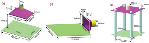
Both updraft and side-draft dust exhaust hoods have an open free suction space, which can drive the dust away during the suction process. The workbench, where the dust-producing source was located, was 900 mm × 1200 mm in size. The release range of the source was approximately 500 mm x 700 mm. Updraft and side-draft exhaust hoods, which are commonly used in actual production, were investigated in this study. As shown in , the updraft exhaust hood was located 0.7 m above the workbench, whose air inlet was 520 mm x 760 mm in size; the side-draft exhaust hood, with a 300 m x 700 m air inlet, was located on the right of the workbench.
Figure 1. Commonly-used dust exhaust hoods: (a) air updraft exhaust hood (b) Side suction exhaust hood (c) Air-curtain exhaust hood
According to the related design specifications for ventilation dust removal, the sectional airflow velocity of the updraft exhaust hood was controlled to be above 0.15 m/s (Xiaodong Citation2013), and the exhaust airflow rate, denoted as Q[m3/s], can be calculated as
where P[m] is the perimeter of the open face at the hood opening; H[m] is the distance between the hood opening and the pollution source; K is a safety coefficient with the consideration of uneven velocity distribution and is generally set as 1.1 ~ 1.2 (K = 1.1 in this study); vx [m/s] is the control gas velocity. The suction airflow rate of the updraft exhaust hood was 0.296 m3/s, and the mean airflow velocity in the pipe at the inlet of the exhaust hood was calculated as 14.71 m/s.
For the side-draft exhaust hood, the exhaust airflow rate can be calculated as (Chen Citation2018)
where x[m] is the distance between the dust source and the hood opening, and A[m2] is the area of the hood opening. In this study, x was set to 0.5 m in accordance with the actual condition at the industrial site. The suction airflow rate of the side-draft exhaust hood equaled 0.282 m3/s. The mean airflow velocity in the pipe at the inlet of the side-draft exhaust hood was 14.03 m/s.
For the exhaust hood with rotational air curtain, the square exhaust hood developed by Xiao et al. (Xiao et al. Citation2020) was examined in this study. As shown in , the suction airflow inlet was 1 m away from the workbench. Four air-curtain generators with an identical diameter of 100 mm were arranged at intervals of 1 m. The air outlet of the generator was 10 mm in width. According to the related reference, the airflow velocity at the outlet of the generator was set to 6.27 m/s, and the supply airflow rate of the generator was 0.25 m3/s. Therefore, the suction airflow rate was calculated as 0.226 m3/s since the ratio of the suction airflow rate to the supply airflow rate was 0.9. The airflow velocity at the exhaust outlet was 11.23 m/s.
Governing equations
The flow induced by ventilation dust discharge is turbulent. The flow behaviors of turbulent air and dust were simulated using the Euler–Lagrange method. The continuous gas phase was described by the Navier-Stokes governing equations together with the standard k-ε two-equation turbulence model. After solving the continuous-phase flow equations, the forces acting on the dispersed phase were analyzed using the Lagrange method and the trajectories were computed.
The continuous phase can be described by the following equations.
(1) Continuity equation
(2) Momentum equation
(3) k-ε complementary equations
Turbulent kinetic energy equation (k equation):
Turbulent dissipation rate equation (ε equation):
in which
where u[m/s] is the velocity vector of the gas phase; I is the unit coordinate vector; F[N] is the external force; ρ[kg/m3] is the fluid density; p[Pa] is the pressure; Pk[m2/s3]is the change rate of turbulent kinetic energy; k[m2/s2] is the turbulent kinetic energy; ε[m2/s3] is the turbulent dissipation rate; μ[kg/ms] is the viscous coefficient of laminar flow; μT[kg/ms] is the viscous coefficient of turbulent flow; Cε1, Cε2, Cμ, σε and σk are constants. Generally, Cε1 = 1.44, Cε2 = 1.92, Cμ = 0.09, σε = 1.0 and σk =1.3 (Chen et al. Citation2012; Zare and Hashemabadi Citation2020).
The force acting on the particulate dispersed phase can be expressed by the equation:
By taking into account the fluctuating action, the airflow velocity (ug) for the calculation of drag force should be changed to:
where is mean airflow velocity, and
is the turbulent fluctuating velocity.
can be further expressed as
where ζ represents a normal random distribution with a mean value of 0 and a standard deviation of 1.
Grid generation
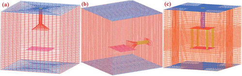
In this study, the model was meshed with the use of ICEM-CFD software. The flow characteristics of a single exhaust hood were first examined. A single exhaust hood and the workbench of 900 mm x 1200 mm were placed in a cubic flow region of 3,000 mm edge. Using a structured grid generation method, the pipe wall and the wall surface of the exhaust hood were meshed more densely to ensure high grid quality. displays the generated grids and lists the test results of the present grid generation. As shown in , the grid quality term which is a parameter of ICEM-CFD software represents the grid convergence. Grid quality of higher than 0.3 shows strong convergence, more generally, grid quality of higher than 0.2 would be acceptable for calculation convergence as an empirical value.
Table 1. Grid information of the model
Figure 2. Grids of (a) air updraft exhaust hood (b) Side suction exhaust hood (c) Air-curtain exhaust hood
Setting of the boundary conditions and simulation method
Setting of main boundary conditions
A flow domain was set in each model. The inlets of surrounding air were set as pressure inlet while the suction port was set as the outlet. The value of gauge pressure of inlet and outlet boundaries was set to be the barometric pressure of 101,325 Pa. Physical wall boundaries were set for both the upper and lower floors (“wall floors”), the exhaust hood (“wall cover”), the pipes (“wall pipe”) and the desktop (“wall desk”).
The operating pressure was set to the barometric pressure (101,325 Pa) and the gravitational acceleration equals 9.8[m/s2].
The velocities at the inlets of the suction pipes of updraft and side-draft exhaust hoods were 14.71 m/s and 14.03 m/s, respectively.
The boundary of air-curtain jet velocity was set as “inlet-wind.” The inlet velocity was 6.27 m/s. The jet was ejected in the direction perpendicular to the air supply groove surface. The velocity at the inlet of the air suction pipe was 11.23 m/s.
Single-phase air flow simulation method
The single-phase airflow was simulated as steady state. The solution technique was based on the pressure-based solver, the standard k-ε two-equation model and standard near-wall functions.
Physical properties of the fluid material in the flow domain were those of “air.” The SIMPLE algorithm was adopted for pressure-velocity coupling. The pressure and momentum equations were discretized by means of second-order central and second-order upwind differences, respectively.
The volume flow rate at the inlet and the velocity at a point referred to as “point 1,” located 0.5 m away from the hood opening, were selected as the convergence monitoring parameters. When the monitoring parameters reached stable or periodic equilibrium and the residuals were smaller than 10−3, the system approached steady-state conditions. At the end of the simulation, the flow lines and the cloud charts of velocity vectors were plotted for further analysis. The main reason for choosing “point 1” is that “point 1” is located in the middle of the calculation domain within the scale of the model, and the airflow has been fully developed, which can better represent the convergence characteristics.
Airflow-dust two-phase flow simulation method and settings
Following the steady-state calculation for the fluid phase, the dispersed phase was added for the subsequent simulation. Using two-way coupling and unsteady particle tracking method, the dust release source was set on the “wall-desk.” lists the related settings of the dust source.
The boundary conditions of the continuous phase were identical to those of the steady-state simulation. The boundary conditions of the dispersed phase at the boundary inlet and outlet were set as “trap” and “escape,” respectively, where the boundary condition type of “trap” means particles arriving this boundary will be trapped and the iteration processes end, the boundary condition type of “escape” means particles will escape from this boundary and then particle simulation processes end. The other wall surfaces were simulated as “reflecting” surfaces.
A uni-directional coupling simulation was first performed. After reaching convergence, a bidirectional coupling simulation was made, with a time step of 0.1 sec for the calculation of the particle motion.
The point located 0.5 m away from the workbench in vertical direction and 0.1 m away from the edge was referred to as “point 2.” The dust concentration at “point 2” and the volume flow rate at the inlet were monitored. When the monitoring parameters reached stable or periodic equilibrium and the residuals were lower than 10−3, the calculation approached steady state and was stopped. The main reason for choosing “point 2” is that “point 2” is located in the middle of the calculation domain within the scale of the model. The gas flow and particle phase flow have been fully developed and can better represent the convergence characteristics.
With a time step of 0.1s the calculation approached convergence at t = 23.5 sec but was stopped only after 700 time steps, i.e., at t = 70 sec.
Table 2. Parameters setting for dust source
During the simulation, dust-capturing efficiency, denoted as ηm, can be calculated as
where mb[kg] is the total mass of the inhaled dust at the suction port, and ma[kg] is the total mass of the dust emitted from the source.
Simulation results of dust-capturing performances of the exhaust hoods
Air flow characteristics of the exhaust hoods
Single-phase airflow provides the frame for evaluating the dynamic process of dust-capturing behavior in the exhaust hood. Without external interference, the escape of dust particles can be adequately controlled at an airflow velocity of 0.4 m/s. displays the flow lines and airflow velocity vector distributions around the exhaust hoods.
Figure 3. Flow lines and velocity vector distribution of single-phase air around the exhaust hoods: (a) updraft exhaust hood, (b) side-draft exhaust hood and (c) air-curtain exhaust hood
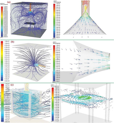
Airflow streamed steadily around the updraft exhaust hood opening, apart from a weak pattern around the workbench far away from the hood opening. With an airflow velocity far below 0.4 m/s, the escape dust around the workbench cannot be effectively captured, as shown in . The updraft exhaust hood can capture ascending hot waste gas but the environmental dust or the exhaust gas may escape with the streaming airflow, so that the updraft airflow cannot achieve effective dust control.
Stable airflow can also be observed around the side-draft exhaust hood opening where the airflow velocity for dust control (0.4 m/s) was established. However, at the position far away from the dust cover, the airflow velocity is lower and the dust removal ability is weakened as shown in .
Four end-to-end air curtains were formed around the air-curtain exhaust hood, which separated the regions inside and outside of workbench. Under suction-induced negative pressure, a rotational airflow was formed and rose in spirals from the bottom to the top. Accordingly, as shown in , the dust can be orderly driven away from the workbench, suggesting less dust escape outwards. It can also be observed from the velocity vectors that airflow velocity in the whole space enclosed by air curtains rose up to 0.4 m/s and thereby exhibited strong dust-controlling capability.
Dust-collecting characteristics of the exhaust hood
After computing the distribution of the continuous phase and adding the dispersed phase, the dust-capturing efficiencies of three exhaust hoods and dust concentration distributions were simulated, obtaining the results shown in and . In terms of dust-capturing efficiency, the updraft exhaust hood showed the lowest performance under the same dust release and similar suction airflow rates, followed by the side-draft exhaust hood, while the air-curtain hood exhibited the highest dust-capturing efficiency. The dust-capturing efficiency of the air-curtain exhaust hood exceeded those of the side-draft and the up-draft hoods by 15.5% and 65.1%, respectively, suggesting a remarkable advantage.
Figure 4. Dust collection efficiency of the three models
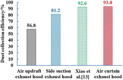
Figure 5. Spatial dust concentration distributions using three different exhaust hoods: (a) updraft exhaust hood, (b) side-draft exhaust hood and (c) air-curtain exhaust hood
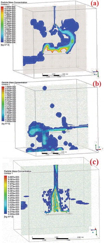
Combined with the analysis of the flow characteristics of single-phase flow, the upward suction and side suction are driven by the suction flow, while the suction flow belongs to the point sink flow, and the influence range of the airflow flow is narrow.
When using open dust collection mode, the updraft and the side-draft exhaust hoods control a wide flow domain, thereby exhibiting poor dust-capturing capability. By further analyzing the spatial dust concentration distribution, it can be concluded that, with the use of the updraft exhaust hood, dust began to diffuse outwards after leaving the workbench. As the dust further ascended, it was captured near the hood opening while it escaped in the other regions, as shown in .
The side-draft exhaust hood was installed near the dust-producing source but extended far away from the workbench. Accordingly, the dust near the side-draft exhaust hood was significantly captured while far-away it escaped. In addition, the workbench far away from the exhaust hood was almost unaffected by the suction airflow. As shown in , the dispersed dust was freely settled and then scattered on the ground near the workbench.
When using the air-curtain exhaust hood, a jet formed and traveled far away thus effectively controlling and discharging the dust within the wrapping range of the air curtain. It can also be observed from the spatial dust concentration distribution that dust was subjected to the control of swirling airflow and rarely escaped outwards from the controlling range. Accordingly, as shown in , high-concentration dust was collected at the center of the swirling airflow, indicating favorable dust separation and capturing performances.
Effects on the dust-capturing efficiency of the air-curtain exhaust hood
The dust-capturing efficiency of the air-curtain exhaust hood fits well with the experimental results by Xiao et al. (Xiao et al. Citation2020) as shown in . Therefore, the air-curtain exhaust hood was selected as the optimal scheme. An exhaust hood should be designed by taking into account the aspect ratio between long- and short-side air curtain. Next, we will report about both simulations and experiments carried out in this study to provide data reference for non-square plane structure.
Experimental scheme
Optimization of physical model and grid generation
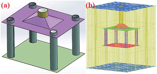
According to the workbench size and flow characteristics, the transition section at the suction inlet is more conducive to the airflow; however, in the study of Xiao et al. (Xiao et al. Citation2020), direct connection is adopted, which is not conducive to the flow of air. A rectangular air-curtain exhaust hood with a size of 900 mm x 1200 mm was designed, and a rectangular transition section was added at the suction port of the hood for enhancing suction fluency. The inlet of the exhaust hood was 0.7 m above the workbench. The inner diameter of the air supply column and the diameter of the air suction pipe increased by 110 mm and 180 mm, respectively. displays the established physical model. Using the grid generation method described in Section 2.3, the external flow domain was set and the model was meshed, as shown in . A total of 374,652 grid points (nodes) in total were generated, with a quality of over 0.3.
Figure 6. Air-curtain dust hood on the workbench, (a) physical model and (b) gridded model
Setting of boundary conditions
The outlet boundary was set as mean flow velocity in the suction pipe. The dust source was set at the center of the workbench and occupied an area of 850 mm x 550 mm. The time step for computing the particle motion was 0.1 sec. When the dust concentration, monitored at point 2, reached stable or periodic equilibrium and the residuals were lower than 10−3, convergence was assumed and the calculation was stopped. This occurred at t = 60 sec. The settings of the other boundary condition and parameters were identical to those in Section 2.4.
Experimental materials and facility
In this study, tobacco dust particles were used as raw material. The tobacco was dried at 60°C for 6 hours and crushed by a grinder. Next, the particulate matter with large size was sieved out via 120-mesh sifter and the dust particles were dried again for 3 hours. The dust particle size was measured by means of counting under the microscope. The dust particles with size smaller than 5 μm, in the range 5 ~ 10 μm and in the range 10 ~ 20 μm occupied 31.55%, 34.56% and 14.11% of the total, respectively. The dust density was measured as 826.17 kg/m3.
The structural size of the air-curtain exhaust hood was the same as that of the simulation model. By reference to the experimental system developed by Xiao et al. (Xiao et al. Citation2020), the dust release device (is same as Xiao et al. (Xiao et al. Citation2020)) was placed in the middle of the workbench, and a ZGF-3 dust sampler was employed for measuring dust concentration outside of the air curtain. Additionally, a frequency converter was used for adjusting the air-curtain jet and suction airflow velocities, and a TES-1340 hot-wire anemometer was used for airflow monitoring.
Experimental method
During the dust-capturing efficiency simulations, air-curtain velocity and the suction velocity of the exhaust hood were set to different values for examining their effects on the dust-capturing efficiency of the air-curtain hood. First, by fixing the airflow velocity in the suction pipe at 10 m/s (with a corresponding flow rate of 15.24 m3/min), the long-side air-curtain velocity increased from 0 to 12 m/s, and the short-side air-curtain velocity was 80% (the data were determined according to the previous experimental data) of the long-side velocity. Afterward, the long-side and the short-side air-curtain velocities were set to 4 m/s and 3.2 m/s, and the airflow rate in the suction pipe increased steadily within a range of 0 ~ 15 m3/min. The dust-capturing efficiency was calculated according to EquationEq. (12)(12)
(12) .
A laboratory test was also performed for experimentally examining the effects of air-curtain velocity and the suction velocity of the exhaust hood on dust-capturing efficiency. The related experimental parameters were similar to those used in the simulation. Since the dust concentration measurement was quite difficult in the suction pipe at a high velocity, the dust-capturing efficiency, denoted as ηe, was calculated according to concentration contrast method, which is same as Xiao et al. (Xiao et al. Citation2020):
where Mb and Ma (both in kg/m3) denote the dust concentration outside the workbench before and after the opening of the air-curtain exhaust hood, respectively.
Research results and discussion
Effect of air-curtain velocity on dust-capturing efficiency
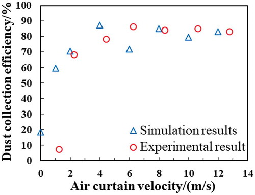
The simulation results fit well with the experimental data. As shown in , air-curtain velocity significantly affected dust-capturing efficiency. As the air-curtain velocity increased from a low value to 2 m/s, dust-capturing efficiency increased from values below 20% to approximately 70%, and then reached a maximum of 87.6% at an air-curtain velocity of 4 m/s. In the experiment, the measured dust-capturing efficiency increased to 86.4% at an air-curtain velocity of 6.27 m/s. The dust-capturing efficiency slightly dropped with the further increase of air-curtain velocity. Therefore, the air-curtain exhaust hood possessed high dust-capturing efficiency in the air-curtain velocity wide range of 4 ~ 6.27 m/s. Dust-capturing efficiency cannot be remarkably enhanced by further increasing air-curtain velocity beyond that range. Accordingly, efficient and economic air-curtain velocity of the exhaust hood can be acquired.
Figure 7. Effect of air-curtain velocity on dust-capturing efficiency
Effect of suction airflow rate on dust-capturing efficiency
displays the simulation and the experimental results when the suction airflow rate was set to different values. The experimental and the simulation results were in good agreement when the suction airflow rate was larger than about 3.6 m3/min. Both the experimentally measured and simulated dust-capturing efficiency increased slowly with the suction airflow rate. The experimental data were overall slightly smaller than the simulation results. As regard to the maximum dust-capture efficiency, the simulated value was 86.5%, while the experimental value was 79.6%, with a difference of 6.9%. The difference may be related to different calculation methods in both experiment and simulation. In the simulation, the total number of captured and released particles was assessed with statistical methods. The experimental value was obtained by calculating the ratio of the dust concentrations at the same position before and after the opening of the exhaust hood. Due to the diffusion effect, the dust outside the exhaust hood was diluted by the airflow in the laboratory, thereby causing the decline in the concentration of escaped dust. However, at a suction airflow rate below 3.6 m3/min, the simulated dust-capturing efficiency was low. This is due to the fact that little dust was driven away by the airflow at a low suction rate. According to the above data, it can be concluded that the suction airflow most significantly affects the dust-capturing efficiency of the air-curtain exhaust hood.
Figure 8. Effect of the suction airflow rate of the exhaust hood on dust-capturing efficiency
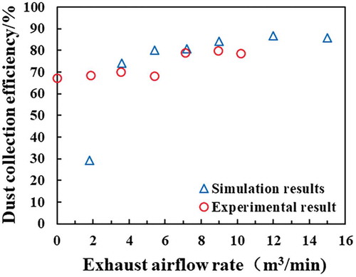
Overall, both simulation and experimental results demonstrated that dust-capturing efficiency increased with the increasing suction airflow rate of the exhaust hood. At a suction airflow rate in the range 0 ~ 5.4 m3/min, the dust-capturing efficiency increased significantly with increasing suction rate. As the suction airflow rate further increased above 5.4 m3/min, the dust-capturing efficiency rose slowly. At a suction ratio above 15 m3/min, the dust-capturing efficiency even dropped slightly. Therefore, by taking the economic benefit into account, appropriate suction airflow rate should be set within the range 5.4–9 m3/min.
Conclusion
This study simulated dust-capturing performances of updraft, side-draft and air-curtain dust exhaust hoods. The simulation results fit well with measured data. The upright exhaust hood performed worst in dust capture, with a dust-capturing efficiency of 56.8%, while the air-curtain exhaust hood had the highest dust-capturing efficiency of 93.8%.
The dust-capturing efficiency of the rectangular air-curtain exhaust hood was greatly affected by both air-curtain velocity and the suction airflow rate. Both simulation and experimental results demonstrated that dust-capturing efficiency increased rapidly with the air-curtain velocity and suction airflow rate. The dust-capturing efficiency stabilized when the air-curtain velocity and the suction airflow rate exceeded certain values.
For a rectangular air-curtain dust exhaust hood with a size of 900 mm x 1200 mm, the appropriate long-side air-curtain velocity and suction airflow rate should be set in the range 4–6.27 m/s and 5.4–9 m3/min. With appropriate settings, the dust-capturing efficiency of the exhaust hood can be as high as 79.6–86.5%.
Disclosure statement
No potential conflict of interest was reported by the authors.
Additional information
Funding
Notes on contributors
Yang Liu
Yang Liuc is an Associate Professor in School of Nuclear Science and Engineering, North China Electric Power University, People's Republic of China.
Tianjie Xia
Tianjie Xia is a master candidate in School of Nuclear Science and Engineering, North China Electric Power University, People's Republic of China.
You Wang
You Wang is a master candidate in MOE Key Laboratory of Thermo-Fluid Science and Engineering, Xi'an Jiaotong University, People's Republic of China.
Jinzhu Chen
Jinzhu Chen is a master candidate in School of Nuclear Science and Engineering, North China Electric Power University, People's Republic of China.
Xiaochuan Li
Xiaochuan Li is an Associate Professor in School of Chemical Engineering and Technology, China University of Mining and Technology, People's Republic of China.
References
- Betta, V., F. Cascetta, P. Labruna, and A. Palombo. 2004. A numerical approach for air velocity predictions in front of exhaust flanged slot openings. Build. Environ. 39 (1):9–18. doi:10.1016/j.buildenv.2003.07.004.
- Candra, K. J., S. A. Pulung, and M. A. Sadashiv. 2014. Dust dispersion and management in underground mining faces. Int. J. Mining Sci. Technol. 24 (1):39–44. doi:10.1016/j.ijmst.2013.12.007.
- Cascetta, F., and F. M. M. Rosano. 2001. Assessment of velocity fields in the vicinity of rectangular exhaust hood openings. Build. Environ. 36 (10):1137–41. doi:10.1016/S0360-1323(00)00087-1.
- Chen, J. 2018. Research on the axial velocity change rule of desktop slot exhaust hood. Ind. Health 56 (4):278–84. doi:10.2486/indhealth.2017-0211.
- Chen, X. L., C. A. Wheeler, T. J. Donohue, R. Mclean, and A. W. Robert. 2012. Evaluation of dust emissions from conveyor transfer chutes using experimental and CFD simulation. Int. J. Mineral Process. 110-111:101–08. doi:10.1016/j.minpro.2012.04.008.
- Deming, W. 2015. Mine dusts, 134–35. Beijing: Science Press.
- Ferge, T., J. Maguhn, H. Felber, and R. Zimmermann. 2004. Particle collection efficiency and particle re-entrainment of an electrostatic precipitator in a sewage sludge incineration plant. Environ. Sci. Technol. 38(5):1545–53. doi:10.1021/es034709s.
- Guo, Y., L. Luo, Y. Zheng, T. Zhu, and M. Ye. 2020. Influence of pollutants’ control facilities on PM2.5 profiles emitted from an iron and steel plant. Environ. Technol. 41 (4):521–28. doi:10.1080/09593330.2018.1504123.
- Li, X., X. Xu, M. Zhang, and Y. Jiao. 2019. Column dust scrubber based on the orifice plate to intensify the gas-liquid mixing. Chem. Eng. Technol. 42 (11):2302–09. doi:10.1002/ceat.201800685.
- Logachev, K. I., A. M. Ziganshin, and O. A. Averkova. 2018. Simulations of dust dynamics around a cone hood in updraft conditions. J. Occup. Environ. Hyg. 15 (10):715–31. doi:10.1080/15459624.2018.1492137.
- Logachev, K. I., A. M. Ziganshin, and O. A. Averkova. 2020. A study of separated flows at inlets of flanged slotted hoods. J. Build. Eng. 29 (May):101159. doi:10.1016/j.jobe.2019.101159.
- Patel, M. K., M. Kundu, H. K. Sahoo, and M. K. Nayak. 2016. Enhanced performance of an air-assisted electrostatic nozzle: Role of electrode material and its dimensional considerations in spray charging. Engi. Agric. Environ. Food 9 (4):332–38. doi:10.1016/j.eaef.2016.05.002.
- Pinelli, M., and A. Suman. 2014. A numerical method for the efficient design of free opening hoods in industrial and domestic applications. Energy. 74 (September). Elsevier Ltd:484–93. doi:10.1016/j.energy.2014.07.014.
- Ru, Y., L. Zhao, S. Lara Jane, H. Zhu, and S. K. Ramdon. 2017. Laboratory evaluation of electrostatic spray wet scrubber to control particulate matter emissions from poultry facilities. Environ Technol. 38(1):23–33. doi:10.1080/09593330.2016.1184319.
- Xiaodong, X. 2013. Dust suppression theory and technology [M]. Beijing: Metallurgical Industry Press.
- Xiao, D., X. Li, Z. Fang, W. Yan, Y. Jiang, and X. Zhao. 2020. Investigation of the dust control performance of a new transverse-flow air curtain soft-sealing system. Powder Technol. 362:238–45. doi:10.1016/j.powtec.2019.11.091.
- Xiao, D., X. Li, W. Yan, and Z. Fang. 2019. Experimental investigation and numerical simulation of small-volume transverse-flow air curtain performances. Powder Technol. 352:262–72. doi:10.1016/j.powtec.2019.04.063.
- Xiaochuan, L., H. Haibin, X. Di, W. DongXue, and J. Shuguang. 2019. Analysis of the spatial distribution of collectors in dust scrubber based on image processing. J. Air Waste Manage. Assoc. 69 (6):764–77. doi:10.1080/10962247.2019.1586012.
- Xiaochuan, L., W. Qili, L. Qi, and H. Yafei. 2016. Developments in studies of air entrained by falling bulk materials. Powder Technol. 291 (4):159–69. doi:10.1016/j.powtec.2015.12.021.
- Yuan, L. 2020. Scientific conception of coal mine dust prevention and occupational safety and health. J. China Coal Soc. 45 (1):1–7.
- Zare, M., and S. H. Hashemabadi. 2020. Particle-fluid heat transfer close to the bed wall: CFD simulation and experimental study of particle shape influence on the formation of hot zones. Int. J. Therm. Sci. 150:106223. doi:10.1016/j.ijthermalsci.2019.106223.
- Zaripov, S. K., A. K. Gilfanov, and D. V. Maklakov. 2010. Numerical study of thin-walled sampler performance for aerosols in low windspeed environments. Aerosol Sci. Technol. 44 (2):152–60. doi:10.1080/02786820903447214.
- Zhou, Q., B. Qin, F. Wang, H. Wang, J. Hou, and Z. Wang. 2019. Effects of droplet formation patterns on the atomization characteristics of a dust removal spray in a coal cutter[J]. Powder Technol. 344:570–80. doi:10.1016/j.powtec.2018.12.021.