 ?Mathematical formulae have been encoded as MathML and are displayed in this HTML version using MathJax in order to improve their display. Uncheck the box to turn MathJax off. This feature requires Javascript. Click on a formula to zoom.
ABSTRACT
National Institute for Occupational Safety and Health (NIOSH) researchers continue to study worker exposure to respirable crystalline silica (RCS) and develop interventions to reduce these exposures. Occupational overexposures to RCS continue to cause illness and deaths in many industries and RCS has been identified as a serious exposure risk associated with hydraulic- fracturing operations during oil and gas extraction. In 2016 the Occupational Safety and Health Administration (OSHA) reduced the permissible exposure limit (PEL) to 0.05 milligrams of silica per cubic meter of air, averaged over an 8-hour day. This mandate requires hydraulic-fracturing operations to implement dust controls and safer work methods to protect workers from silica exposures above this PEL by June 23, 2021. At hydraulic-fracturing sites utilizing sand movers, pneumatic transfer of fracking sand is the primary source of aerosolized RCS. Currently, there are limited commercially available engineering controls for the collection of dust emitted from thief hatches on sand movers. The goal of this research is to develop a robust, cost-effective, weather resistant, portable, self-cleaning dust collection system that can be retrofitted onto sand mover thief hatches. A prototype was designed, built, and tested, and it was determined that the system could handle flows in the range of 600 to 1300 cfm with loading/cleaning cycle times of 40 and 5 minutes respectively and demonstrated operating efficiencies of 97–99%. Further development of this NIOSH prototype is being done in collaboration with an industry partner with the goal of developing a commercially viable, cost-effective solution to reduce RCS at hydraulic-fracturing sites around the world.
Implications: This research has verified that airborne dust created by pneumatic transfer of fracking sand can be effectively collected using a passive cartridge filter system, and that the filters can be cleaned using blasts of air. Mounting these units to the thief hatches of sand movers will significantly reduce dust emissions from sand movers on hydraulic fracturing sites. Thus, this system offers the Oil and Gas Industry a method to reduce worker exposure to RCS on hydraulic fracturing sites that utilize sand movers. The success of this prototype has led researchers to devise a modified version for collecting dust at conveyor transfer points.
Introduction/Background
Due to the continued illness and deaths caused by overexposures to respirable crystalline silica (RCS), researchers at the National Institute for Occupational Safety and Health (NIOSH) continue to study worker exposure to RCS and develop interventions to reduce these exposures. Depending on exposure dose and duration, occupational exposure to RCS can lead to the development of silicosis (Leung, Yu, and Chen Citation2012), lung cancer (IARC Citation2012; Straif et al. Citation2009), and other respiratory diseases (OSHA/NIOSH Citation2012). Silicosis puts workers at higher risk of developing tuberculosis and has been linked to kidney and auto-immune diseases (Castranova and Vallyathan Citation2000; Pollard Citation2016), and while the causes and effects of silicosis have been known for nearly a century, it remains a severe and persistent occupational hazard (ALA Citation2020). The International Agency for Research on Cancer (IARC) classifies crystalline silica dust (quartz or cristobalite, two of the most common crystalline forms) as carcinogenic to humans, based on epidemiologic and animal studies (IARC Citation2012). The U.S. National Toxicology Program (NTP) also classifies RCS in the form of quartz or cristobalite as a known human carcinogen (NTP Citation2016).
NIOSH researchers have identified RCS as a particularly serious exposure risk associated with hydraulic-fracturing operations during oil and gas extraction (Esswein et al. Citation2013). Hydraulic fracturing is an oil and natural gas production technique that involves the injection of water, chemicals, and sand (proppant) underground at very high pressure in order to create fractures in the underlying geology to allow oil and natural gas to escape (Schlumberger Citation2020). The proppant consists primarily of crystalline silica and during pneumatic transport, the grains of proppant are often broken and release very small particles of RCS. The mixing and transport of proppant sand at hydraulic-fracturing sites is therefore a major source of RCS aerosol generation. Sand movers are large, portable containers typically containing 4 bins used to store sand to be used in the hydraulic-fracturing process. Sand mover bins are filled by sand trucks using a pneumatic transfer process. Many of the RCS particulates generated during this pneumatic transfer of sand, are small and have a “50% cut size of 4 μm or less (Esswein, King, and Miller Citation2015; OSHA/NIOSH Citation2012) which by definition means they are “respirable” in size and can be inhaled and retained in the gas exchange region of the lungs. NIOSH research conducted at multiple work sites determined that in some cases worker exposures to RCS exceeded the NIOSH Recommended Exposure Limit (REL) of 0.05 milligrams per cubic meter (mg/m3) by a factor of more than ten (Esswein et al. Citation2013). Since the published quantification of this silica exposure, NIOSH has continued to conduct research on this topic (Alexander et al. Citation2016), and the Oil and Gas Industry has come up with various solutions to mitigate this hazard, including the use of loading silos and sealed “sand boxes” delivered to the site. The solution presented here is intended as a cost-effective method to retrofit a sand mover to address this silica-exposure hazard.
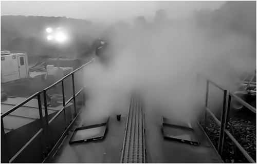
The sand used for hydraulic fracturing is delivered to well sites by dry bulk trailer trucks with on-board power take-off (PTO) driven rotary blowers. Multiple drivers park near a sand mover and offload sand into the sand mover bins (often simultaneously). As the sand exits the pneumatic transfer pipes inside the sand mover, it impinges the interior surfaces of the bins creating respirable dust inside the sand mover. The combined airflow from multiple blowers pressurizes the sand mover and RCS is emitted from thief hatches atop the sand mover bins, creating plumes of RCS dust that can drift across the jobsite, posing an exposure hazard to all workers in the area ().
In order to better protect workers, the Occupational Safety and Health Administration (OSHA) promulgated a regulation to reduce exposures to RCS in 2016. The new OSHA permissible exposure limit (PEL) is 0.05 milligrams of silica per cubic meter of air (in the respirable size range i.e., PM4), averaged over an 8-hour day. This mandate requires hydraulic-fracturing operations in the oil and gas industry to implement dust controls and safer work methods to protect workers from silica exposures above this PEL by June 23, 2021 (OSHA Factsheet Citation2018). This deadline created an urgent need for research aimed at providing effective solutions to prevent RCS overexposures during hydraulic fracturing at oil and gas extraction operations.
Currently, there are limited commercially available engineering controls for the collection of dust emitted from thief hatches on sand movers that can be deployed to retrofit the many sand movers that are still in service (Esswein et al. Citation2019). NIOSH is therefore conducting research with the aim of developing a solution to mitigate dust generated during the loading of sand movers. The focus is on developing a portable dust-collection system that can be retrofitted onto the thief hatches to eliminate such exposures. Previous NIOSH research evaluated a NIOSH-developed mini baghouse retrofit assembly as a potential engineering control and showed that this approach reduced worker exposure to RCS at a work site (Alexander et al. Citation2018). The current research focused on addressing refinements suggested by that earlier NIOSH work, including improving robustness, weather resistance, and developing an effective filter cleaning system. The goal is to develop a dust-collection system for retrofitting onto sand movers that is simple to install, self-cleaning, and requires minimal maintenance. To that end, the study focused on designing and fabricating a self-cleaning dust-collection system and performing laboratory testing to determine the efficacy of the system.
Methods
The study was conducted in two phases: design and testing. Following prototype construction, laboratory testing was conducted to evaluate system performance and, most importantly, effectiveness of the cleaning system under conditions designed to simulate real world applications.
Prototype design
The aim was to design a dust-collection system that is portable (able to be positioned over a thief hatch by two persons), robust enough to withstand the rigor of field use, and adaptable for retrofitting onto sand movers. The design is based on existing filtration technology and comprises a rectangular enclosure that houses four cylindrical cartridge filters which are mounted vertically (Findanis and Southam Citation2012).
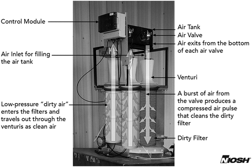
The filters and pulse-jet cleaning system were incorporated inside this housing which was designed to be mounted onto the upward-protruding “lip” of a thief hatch on a sand mover and included an air-tight seal to the lip. The main housing contains four filters and supports the air tank and valve control module (). The aim was to develop and test a prototype system that is robust enough to withstand rugged field use, and uses a filtering element that is compact, easily cleaned, durable, and cost effective. The design was primarily driven by two critical gaps identified during prior testing: preventing rapid overloading of the filters and providing a filter cleaning mechanism.
Figure 2. This dust-collection system utilizes four cartridge filters and a pulse-jet cleaning system.
Rapid filter overloading is normally prevented by balancing the available filter surface area with the expected airflow, i.e., ensuring that the air to cloth ratio (A/C) would be in an acceptable range during operation. The A/C is defined as the ratio of airflow to filter surface area i.e., cfm per square foot of filter area. The term A/C thus has units of velocity, and in fact is sometimes considered synonymous with the term “face velocity” which will be used here. Acceptable face velocity is determined by a number of factors: material factor, application factor, temperature, inlet dust loading, and mass mean diameter of particles (Schousboe Citation2017; Turner et al. Citation1998). If the face velocity of air (and particles) is too high at the filter interface, the particles will tend to penetrate the filter media and “blind” (plug) the filter. This is typically avoided by designing the system such that the face velocity is in the range of 3–10 feet per minute (ft/min) (depending on the factors noted above) (Schousboe Citation2017; Turner et al. Citation1998). When velocity is in this range, or lower, the particles do not penetrate, but instead collect on the outer surface of the filter media forming a surface layer of “cake”. The cake provides two advantages: 1) it is itself an excellent filter media and 2) after sufficient filter cake buildup is achieved, it is more easily removed by a jet pulse.
Unlike many filtration applications, the airflow rate from the thief hatches is not constant but rather can vary considerably depending on the number of trucks that are offloading proppant into the sand mover bins. The variability in flow rate is not problematic but the potential for short term surges in dust concentration may change the required A/C ratio (this will be investigated further in a future field study). In order to maximize flow rate capability and address rapid filter overloading, while minimizing the overall size of the system, pleated cartridge filters were chosen over bag filters (Grafe and Kelley Citation1993). To minimize the footprint, a four-filter arrangement was chosen, and the outer filter diameter was chosen to be less than 9 inches. The filters chosen were the Donaldson Torit TL875 - UltraWeb Spunbond media filters. These filters are specifically designed for use in dust collection systems that use pulse-jet cleaning. They are 8.75 inches in outer diameter, 21.2 inches long, and of a pleated-cartridge filter configuration. This arrangement allowed a relatively small footprint (21 inches by 21 inches), which improves ease of installation and allows room for workers to easily navigate the catwalks on the sand mover. While a filter length of 21.2 inches was chosen for the preliminary design to reduce the overall size of the system, the design also allows the total filter surface area to be easily increased by using longer filters.
Another gap previously identified was the need for an effective filter cleaning mechanism. An advantage of pleated filters is that they are designed for effective cleaning by using jet pulses of air. This combination has been shown to improve filter life (Turner et al. Citation1998). A conventional pulse-jet cleaning system was therefore chosen, consisting of a compressed air tank plumbed to four pneumatic solenoid valves, one directly above each filter (). The valves are triggered in sequence when the pressure drop across the filters reaches an “upper threshold” and continue pulsing until the pressure differential drops to a pre-set “lower threshold”, at which time the cleaning cycle is complete. The power required for an air compressor and for the controller that monitors the differential pressure and activates the solenoid vales will be provided by the on-board diesel engine that powers the operations of the sand mover.
For the design tested in this study, we incorporated a venturi flow-director between each air valve and corresponding filter because it can reduce energy consumption and improve filter cleaning efficiency (Lu and Tsai Citation1998). Our results suggest that little was gained in this case, so to reduce the size and cost of the system, it will be omitted from future iterations of the design.
Lab Testing
Lab testing comprised two primary experiments, the first of which focused on evaluating the performance of the pulse-jet cleaning system and the second on evaluating cleaning effectiveness.
Pulse-Jet optimization
The goal of the first experiment was to optimize the combination of three variables that determine the effectiveness of the air-jet pulse: source pressure, pulse duration and nozzle standoff distance – the distance from the tip of the nozzle to the top of the filter (nozzle size and source-tank air volume were held constant). The experiment was designed to determine which combination of the three parameters would provide a strong and stable air pulse that travels the length of the cartridge filter, removing the dust cake from the entire filter surface. To that end, a series of parametric tests were conducted in which one of the three variables (jet pressure, standoff, and pulse duration) was changed while the other two were held constant. The jet pressure was varied between 40–100 pounds per square inch (psi), the standoff distance between 1 to 8 inches, and the pulse duration between 50–250 milliseconds (ms).
For each condition, five single-pulse tests were conducted, in which the pulse-generated velocity on the inside of the filter was measured at six positions along the vertical axis of the outside of the cartridge filter using a Q-Trak Model 7575 (TSI Inc., Shoreview, MN) with hot wire anemometer probe. The air velocity is a surrogate for “pulse intensity” at locations along the filter. The five air pulse velocity measurements were averaged for each of the six locations, and the data compiled to create “pulse profiles” for each test condition. The profiles were then evaluated to help determine a combination of the three key variables that would produce a strong stable pulse, using the least amount of energy.
Effectiveness of pulse-jet cleaning
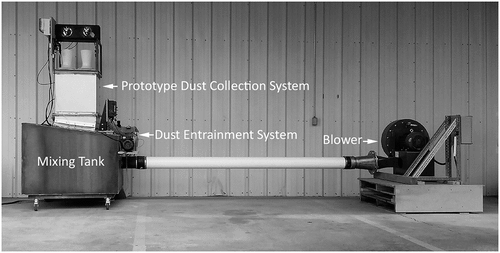
The second lab experiment was designed to measure the rate of dust loading on the filters and the effectiveness of the pulse-jet cleaning. A lab testbed was designed to simulate conditions that would exist during typical pneumatic transfer of frack sand into a sand mover at an oil and gas well site, most notably to recreate both the high volume of airflow as well as the typical concentration of fine dust that exists inside the sand mover bins. The three main components of the testbed are a blower, a dust generator, and a large mixing tank ().
The blower was selected to provide adequate flow and pressure to simulate the conditions that would exist when six trucks are blowing sand into a sand mover (~800 cfm each), and four dust collectors are filtering the effluent (~1200 cfm per unit). The blower must also have enough power to overcome the static pressure in the tank resulting from filter loading. We therefore selected a New York Blower – Model 1708A with a 7.5 horsepower motor that is capable of 2000 cfm at backpressures up to 15 inches of water gauge (iwg).
The dust generator feeds dust into the air stream as it travels from the blower into the mixing tank, creating a dense cloud of fine dust inside the tank, which is subsequently removed as the air exits through the filters. During testing, the differential pressure across the filters is monitored by the control module. When the pressure reaches a predetermined value (the filters are dirty), the control module activates a solenoid bank that fires the air valves one at a time, sending a compressed air pulse into each filter until the pressure differential drops to a predetermined value (the filters are clean).
Before testing, the system was run for several hours at a flowrate of ~ 1000 cubic feet per minute (cfm) and dust concentration of ~300 mg/m3 – these parameters were chosen because they are typical of values measured in the field. (Note: all dust concentrations measured and reported in this paper are for “total dust” i.e., measured without the use of a size-selector, and all flow rates are in standard cubic feet per minute.)
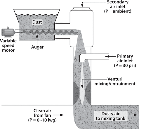
Based on measurements obtained in the field during the mini-baghouse testing, dust concentrations expected (approximately 300 mg/m3) were simulated by injecting rock dust into the airflow stream. The injection system was built in-house and utilizes a variable speed motorized auger to move dust from a hopper at a controlled rate. The hopper is equipped with a pneumatic shaker to ensure the constant flow of dust from the hopper into the auger. Exiting the auger, the dust is drawn into the inlet of an ejector-style dust generator. The high-pressure ejector nozzle and a venturi mixing-section aspirate the dust, aerosolize it at high velocity, and mix it into the primary airflow from the blower ().
As a surrogate for frac-sand dust, tests were conducted with Mine Safety Dust – limestone rock dust (Hubercarb Q100 from the JM Huber Corporation), which is typically used in coal mines to mitigate explosion potential. It has a high content of respirable-sized particles (less than 4 µm), similar to what has been observed in the air at hydraulic-fracturing sites (Esswein, King, and Miller Citation2015) and will therefore behave similarly to the frack sand dust in terms of interaction with the filter materials (Soo et al. Citation2016; Turner et al. Citation1998). Due to its small size, the rock dust was also easily aerosolized by the high velocity air in the ejector, mimicking realistic dust concentrations inside the dust box. The low silica content of the rock dust was also a determining factor, as it insured the safety of personnel conducting the tests.
Five separate tests were conducted to evaluate rate of dust loading and cleaning effectiveness. At the start of each test, the blower was set to a specific flow rate (600, 800, 1000, 1200, or 1300 cfm), and maintained at that rate for the entire test. Dust concentration inside the mixing tank was kept approximately constant at a value of around 300 mg/m3.
Volumetric flow from the blower into the mixing tank was calculated by measuring the velocity in the inlet tube with a VelociCalc Model 9565 (TSI Inc., Shoreview, MN) and multiplying by the cross-sectional area of the tube. A louver valve located near the blower exit was used to control airflow and was used to maintain constant air velocity and thus target flow rate for each trial by close monitoring and adjustment.
Dust concentrations inside the mixing tank were measured in real time using a nephelometer (pDR-1200, Thermo Fisher Scientific, Waltham, MA), while concentrations outside the tank (on the downstream side of the filters, near the pulse-jet nozzles), were measured using a model SPS30 particulate matter sensor (Sensirion AG, Switzerland). Both were calibrated using fine dust, but the Sensirion is designed for low concentrations so was chosen to better characterize the relatively clean air exiting the filters. The real-time readings of dust concentration and flow rate allowed researchers to adjust the fan and dust delivery systems in order to maintain the desired flow rate and targeted concentration (~300 mg/m3) inside the mixing tank for the duration of the various tests. Additionally, the data were used to calculate the filtration efficiency (E) in percent, using EquationEq (1)(1)
(1) - where “x” is the dust concentration after the filter, and “y” the concentration inside the mixing tank.
Measured efficiencies were in the range of 97–99% which is commensurate with the manufacturer’s specifications for the filters, which have a Minimum Efficiency Rating Value (MERV) 15 rating (per ASHRAE 52.2)
The key parameter measured during the tests was the rise in differential pressure across the filters as the filters were loaded with dust. High differential pressure is typically avoided in filtration systems, mainly to reduce energy consumption by the fan. However, since energy comes from the blowers on the sand delivery trucks in the pneumatic transfer processes, a fan is not needed to drive the air through the filters, so higher static pressures are allowable without detriment. Based on observations in the field (Alexander et al. Citation2018), even though blower operators can usually maintain proper flow for pneumatic transport into the bins until the static pressure reaches about 10 iwg, at around 8 iwg the pressure creates RCS leakage around the slide gates at the bottom of the bins, creating another source of RCS in the working area. We therefore used 7 iwg as our upper threshold for pressure differential. One advantage of passive systems (such as this) is that high static pressure is an advantage, driving flow more readily through a thicker cake. As such, the use of a relatively high threshold value (7 iwg), potentially lengthens the time between cleaning cycles and produces more effective cleaning.
The cleaning system also has a lower threshold, which is the differential pressure at the end of the cleaning cycle. For all tests, the lower threshold was set at 2.5 iwg. This value was determined by measuring the pressure differential attainable after multiple loading/cleaning cycles using air-only flow through the filters at the highest flow rate (1300 cfm) and adding approximately 0.5 iwg to that value in order to make sure the lower threshold was easily attainable at all flow rates when filters were not compromised.
Differential pressure was measured, and the air-jet pulses controlled, using a Pentair/Goyen ECS control system, and pressure was also monitored manually during tests with a magnehelic pressure gauge (both of which were calibrated using a manometer). The Pentair/Goyen ECS was programmed to initiate air-jet pulses at 7 iwg while also controlling air pulse duration. The air supply pressure (and pulse pressure by extenuation) was manually set by adjusting a regulator on the pressure tank. The parameters for all tests were determined from the earlier experiment and the sequence for the tests was as follows:
Start instruments to measure velocity, dust concentration, and pressure differential
Start fan, adjust louver valve at fan exit to set desired velocity/flow rate
Monitor velocity measurements, adjust louver to maintain constant velocity
Supply 30 psi supplemental air to activate the dust delivery system (ejector) and shaker
Add dust by starting auger and adjusting speed to maintain constant dust concentration of ~300 mg/m3 inside the mixing tank and filter housing
Measure/record the dust concentration both inside and outside the filter housing
Results/Discussion
Pulse-Jet optimization
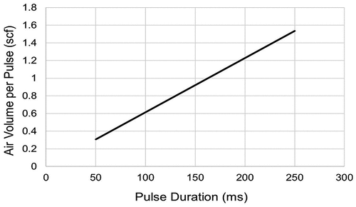
The goal of this experiment was to identify the operating parameters that would yield a strong pulsing effect along the entire length of the filters. During each pulse, the instantaneous flow through the activated nozzle reaches sonic velocity (resulting in critical flow) and the pressure in the tank drops suddenly. It is important that the supply pressure remains high enough to produce critical flow during the entire duration of the air-jet pulse, to provide a sustained and predictable pulse intensity. To explore this, we calculated the air required per pulse, assuming critical flow and nozzle coefficient of unity ().
Figure 5. Calculated relationship between air volume (in scf) and pulse duration (ms), assuming critical flow through the nozzle.
For the purposes of our tests, we chose a relatively large tank volume (0.4 cubic feet) and calculated the air volume in standard cubic feet (scf) that the tank would hold at different pressures (), using EquationEq (2)(2)
(2) along with the ideal gas assumption – where (
) is standard volume, (
is actual volume, (
the pressure factor and (
) the temperature factor (the latter two being ratios of absolute values and actual values of the air).
Figure 6. Relationship between air volume in tank (in scf) and pressure in tank (psi), calculated using Eq. 2.
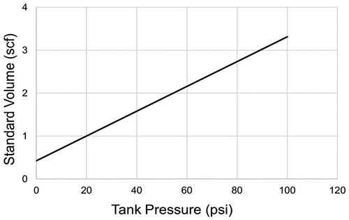
Design aims included minimizing the energy required for air-jet pulsing, which is a function of pulse duration and tank pressure, as well as minimizing tank size. The pressure drop in the tank for various combinations of tank pressure and pulse duration can be estimated from the graphs of . As an example, a pulse duration of 150 ms uses 0.9 scf (), and if original tank pressure is 60 psi (), and the volume of air is reduced by 0.9 scf, the final tank pressure will be around 30 psi. This was confirmed during testing, where we used a tank pressure of 60 psi and recorded a pressure drop of approximately 30 psi during each 150 ms pulse. It should be noted that an excessive pressure differential can cause filter damage.
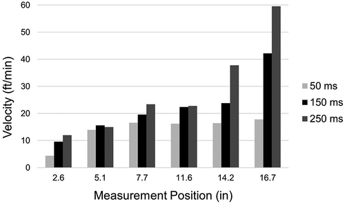
With this in mind, we reviewed the test data with an eye toward optimizing the pulsing effectiveness at various standoffs, especially at low tank pressures. Using shorter standoffs, the data suggest that the air pulses were too focused, creating minimal velocity at the filter surface near the top, and a much greater effect near the bottom of the filter, assumedly when the focused air-jet pulse struck the closed flat end at the bottom of the cartridge filter. With adequate standoff, it was shown that the air-jet pulse spread and was re-focused by the venturi to give a more even pulse. Based on this we chose a standoff of 8 inches for this design iteration.
Having chosen the minimum tank pressure as 60 psi, and a standoff of 8 inches, we reviewed the air-jet pulse data for 3 pulse durations (). Our goal was to select the minimum pulse duration that produced a velocity of around 10 fpm at all filter locations (to overcome the incoming face velocity). Based on the data of we chose a duration of 150 ms. These three parameters (60 psi tank pressure, 150 ms pulse duration, and 8 inch standoff) were thus chosen for this design iteration as they would improve efficiency by using minimal energy, and were therefore used for the subsequent experiment to evaluate the dust loading rate and effectiveness of the cleaning system.
Rate of dust loading and effectiveness of cleaning cycles
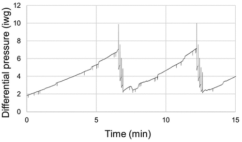
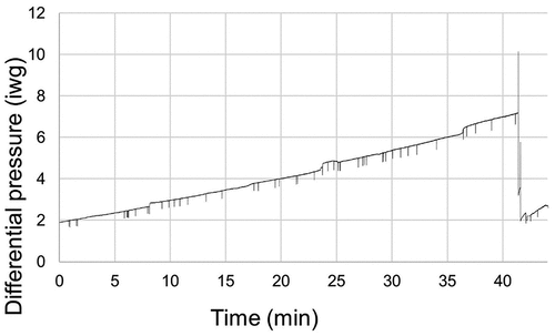
The goals of this experiment were to quantify the rate at which dust builds up on the filters and evaluate the effectiveness of the autonomous jet-pulse cleaning system. The most important variable measured during testing was the pressure differential across the filters. The rate at which the pressure differential rises represents the loading rate i.e. the rate of dust buildup on the filters (). This rate is represented by the rising slope of the “sawtooth” in the plotted data, each sawtooth representing a loading/cleaning cycle.
In addition to determine the loading rate, these data also show the effects of the cleaning pulses (note the “spiking” events on the downward trends at the end of each cycle, where each peak represents an air-jet pulse through one of the four filters). The number of cleaning-pulse peaks varies between a low of two (at the 600 cfm flow rate), and a high of five (for both the 1200 and 1300 cfm flow rates).
It is also notable that for high flow rates () the differential pressure rises slightly between pulses. This is expected, since at high flow rate the filters are loading more quickly and are loading at a measurable rate even as they are being cleaned. At such high flow rates, all four filters must be clean for differential pressure to reach the lower threshold, and this was achieved in all cases with no more than five pulses.
At lower flow rates () the loading/cleaning cycle time is much longer, and fewer cleaning pulses are needed to reach the lower threshold, demonstrating the excellent performance of the cartridge media at low flow rates.
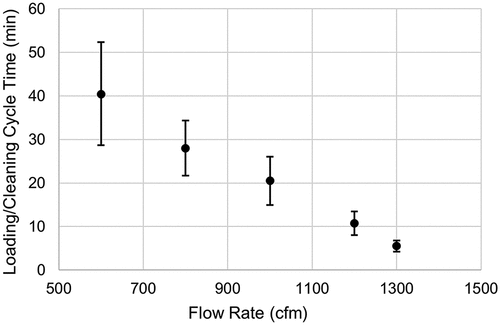
The filter loading rate and loading/cleaning cycle time would be expected to be constant if the airflow and the dust concentration are constant. During our evaluations, the flow rate and dust concentration were not exactly constant and thus, filter loading/cleaning cycle times varied. The average time for a loading/cleaning cycle was calculated from the pressure data for each flow rate (). The cycle time included the time it took the differential pressure to rise from the lower threshold to the upper threshold (loading) and then drop back to the lower threshold (cleaning). Note that the variability in the averaged data was greater for low flows, due to longer test times which introduce more variability in flow rate and dust concentration over the longer cycle times (due to adjustments made during tests).
The test results indicate that the system as designed can handle flow rates up to around 1300 cfm. It is notable that this represents a face velocity of about 9 or 10 feet per minute (fpm) which is the upper limit of suggested face velocities for mineral dusts (Turner et al. Citation1998). If flow rates higher than 1300 cfm are expected in field applications, longer cartridge filters may be advised in order to lower the face velocity and improve filter life by providing more filter surface area.
Conclusion
This study focused on developing a dust-collection system to control emissions of RCS from thief hatch openings during pneumatic loading of sand movers during hydraulic-fracturing operations at oil and gas completion sites. A prototype dust-collection system was designed, built, and tested with the aim of developing a portable, compact, self-cleaning system that could be easily retrofitted onto sand movers. The system was designed with a small (21 inches by 21 inches) footprint and included four cylindrical pleated cartridge filters that are cleaned by blasts of air from air valves. The system is passive, taking advantage of the airflow generated by the pneumatic blowers that load the sand movers, and requires minimal power to control the air valves and charge the air supply tank.
Test results demonstrated that the system could handle flows in the range of 600 to 1300 cfm with loading/cleaning cycle times of 40 and 5 minutes respectively and demonstrated filtration efficiencies of 97–99%. The deployment of a system such as this has the potential to protect workers from overexposure to RCS and could be used to comply with the new OSHA dust controls regulation for the oil and gas industry.
Additional research is needed to further refine the design, including increasing the amount of active filtering area to handle potential surges in dust mass, minimizing the air storage tank size, and allowing for ease of filter changing. In addition, an internet-enabled sensing array could be added to monitor the performance of the filtration system. The sensors could also have satellite connectivity, so that the system can be monitored and controlled even when no WiFi or cell service is available, which often is the case for remote hydraulic-fracturing sites.
An improved prototype will be built and tested under a cooperative research agreement with an industry partner in order to further improve the system, test it under field conditions including wide ranges of temperature and humidity, and develop a commercial product. That agreement includes a plan for building a beta version of the product and field-testing various versions of this prototype.
Disclaimer
The findings and conclusions in this manuscript are those of the authors and do not necessarily represent the views of the National Institute for Occupational Safety and Health.
Acknowledgment
The authors would like to thank David Koski for his efforts in designing system components, creating mechanical drawings, and providing technical support, and the JM Huber Corporation for donating the Mining Safety Dust used for the tests in this study.
Disclosure statement
No potential conflict of interest was reported by the author(s).
Data availability statement
The data that support the findings of this study are available from the corresponding author, GWK, upon reasonable request.
Additional information
Funding
Notes on contributors
Grant King
Grant King is a Mechanical Engineer who has worked in the Health and Safety Research Field for more than 30 years. His specialties include electro-mechanical systems integration, machine guarding, robotics, and machine design. Lately, his efforts have been aimed at improving airborne dust collection at hydraulic fracturing sites. His professional endeavors have predominately focused on improving worker safety in the Oil and Gas, Commercial Fishing, Mining, and Robotics Industries.
Arthur Miller
Arthur Miller is a PhD engineer who conducted mine safety research at NIOSH for over 30 years. He has a broad background in Civil, Aeronautical and Mechanical engineering, and his specialty is air quality. His many publications cover topics including dust, diesel particulate matter (DPM), silica and nanoparticles, and the focus was often on methods of measuring and characterizing airborne contaminants. He is currently working for NIOSH as a technical consultant.
Carl Schneider
Carl Schneider is an electrical engineer who graduated from Eastern Washington University. His specialties include: developing control and communication systems, electro-mechanical systems integration, and data-acquisition solutions. He has also designed and implemented multiple Internet of Things solutions for use in the industrial mining environment. These included implementing end to end (sensor to internet) communication solutions for various network topologies, as well as analyzing and presenting data visualizations and models associated with that system.
Greg Feagan
Carl Schneider is an electrical engineer who graduated from Eastern Washington University. His specialties include: developing control and communication systems, electro-mechanical systems integration, and data-acquisition solutions. He has also designed and implemented multiple Internet of Things solutions for use in the industrial mining environment. These included implementing end to end (sensor to internet) communication solutions for various network topologies, as well as analyzing and presenting data visualizations and models associated with that system.
Greg Feagan is an engineering technician for the NIOSH Spokane Mining Research Division. He studied electronics and instrumentation in the US Air Force and worked in the aviation and electronics industries for ten years. He then worked in a manufacturing environment for thirteen years producing engineering plans, documents, and software. He has assisted in numerous lab and field research projects related to mining industry safety.
Darby Gain
Greg Feagan is an engineering technician for the NIOSH Spokane Mining Research Division. He studied electronics and instrumentation in the US Air Force and worked in the aviation and electronics industries for ten years. He then worked in a manufacturing environment for thirteen years producing engineering plans, documents, and software. He has assisted in numerous lab and field research projects related to mining industry safety.
Darby Gain has a B.S. in Aerospace Engineering with a concentration in Astronautics. She recently graduated from Embry-Riddle Aeronautical University. She completed an internship at NIOSH under the instruction of Dr. Arthur Miller where she contributed to the testing of the self-cleaning portable dust collector and the technical report.
References
- Alexander, B. M., E. J. Esswein, M. G. Gressel, J. L. Kratzer, H. Amy Feng, B. King, A. L. Miller, and E. Cauda. 2016. The development and testing of a prototype mini-baghouse to control the release of respirable crystalline silica from sand movers. J. Occup. Environ. Hyg. 13 (8):628–38. doi:10.1080/15459624.2016.1168239.
- Alexander, B. M., E. J. Esswein, M. G. Gressel, J. L. Kratzer, H. A. Feng, A. L. Miller, E. Cauda, and G. Heil. 2018. Evaluation of an improved prototype mini-baghouse to control the release of respirable crystalline silica from sand movers. J. Occup. Environ. Hyg. 15 (1):24–37. doi:10.1080/15459624.2017.1376068.
- American Lung Association (ALA). Learn about silicosis. Accessed March, 2020. https://www.lung.org/lung-health-diseases/lung-disease-lookup/silicosis/learn-about-silicosis.
- Castranova, V., and V. Vallyathan. 2000. Silicosis and coal workers’ pneumoconiosis. Environ. Health Perspect. 108 (Suppl 4):675–84. doi:10.1289/ehp.00108s4675.
- Esswein, E. J., M. Breitenstein, J. Snawder, M. Kiefer, and W. K. Sieber. 2013. Occupational exposures to respirable crystalline silica during hydraulic fracturing. J. Occup. Environ. Hyg. 10 (7):347–56. doi:10.1080/15459624.2013.788352.
- Esswein, E. J., B. King, and A. L. Miller. 2015. Particle size distribution and shape of silica dust aerosols generated during sand transfer: Size matters. AIHce Conference, Salt Lake City, UT, May 30.
- Esswein, E. J., B. King, M. Ndonga, and E. Andronov. 2019. Respirable crystalline silica is a confirmed occupational exposure risk during hydraulic fracturing: What do we know about controls? Proceedings from the silica in the oil field conference. J. Occup. Environ. Hyg. 16 (10): 6969-674. doi:10.1080/15459624.2019.1652757.
- Findanis, N., and M. Southam. 2012. Control and management of particulate emissions using improved reverse pulse-jet cleaning systems. Proceedings, Evolving Energy-IEF International Energy Congress, Sydney.
- Grafe, T., and G. Kelley. 1993. Baghouse and cartridge dust collectors: A comparison. Feature Art. Am. Ceram. Soc. Bull. 72 (9):69–73.
- IARC. 2012. Part C: Arsenic, metals, fibers, and dusts/IARC working group on the evaluation of carcinogenic risks to humans. In IARC monographs on the evaluation of carcinogenic risks to humans, ed. IARC. Lyon, France: IARC Publications.
- Leung, C. C., I. T. S. Yu, and W. H. Chen. 2012. Silicosis. Lancet, 379, 9830: 2008-2018.
- Lu, H.-C., and C.-J. Tsai. 1998. A pilot-scale study of the design and operation parameters of a pulse-jet baghouse. Aerosol Sci. Technol. 29 (6):510–24. doi:10.1080/02786829808965587.
- NTP (National Toxicology Program). 2016. Report on carcinogens, fourteenth edition. Research Triangle Park, NC: U.S. Department of Health and Human Services, Public Health Service. https://ntp.niehs.nih.gov/go/roc14.
- OSHA Factsheet. 2018. OSHA’s respirable crystalline silica standard for general industry and maritime. http://www.osha.gov/Publications/OSHA3682.pdf.
- OSHA/NIOSH. 2012. OSHA-NIOSH hazard alert: Worker exposure to silica during hydraulic fracturing. http://www.osha.gov/dts/hazardalerts/hydraulic_frac_hazard_alert.pdf.
- Pollard, K. M. 2016. Silica, silicosis, and autoimmunity. Front. Immunol. 7: 97. doi:10.3389/fimmu.2016.00097.
- Schlumberger. 2020. Oilfield glossary. https://www.glossary.oilfield.slb.com/Terms/h/hydraulic_fracturing.aspx.
- Schousboe, F. C. 2017. Media velocity considerations in pleated air filtration, Dissertation, University of South Florida, Scholar Commons.
- Soo, J. C., T. Lee, W. P. Chisholm, D. Farcas, D. Schwegler-Berry, and M. Harper. 2016. Treated and untreated rock dust: Quartz Content and physical characterization. J. Occup. Environ. Hyg. 13 (11):D201–07. doi:10.1080/15459624.2016.1200195.
- Straif, K., L. Benbrahim-Tallaa, R. Baan, Y. Grosse, B. Secretan, F. El Ghissassi, V. Bouvard, N. Guha, C. Freeman, L. Galichet, et al. 2009. A review of human carcinogens-part C: Metals, arsenic, dusts, and fibres. Lancet Oncol. 10 (5):453–54. doi:10.1016/S1470-2045(09)70134-2.
- Turner, J. H., J. D. McKenna, J. C. Mycock, A. B. Nunn, and W. M. Vatavuk. 1998. Section 6: Particulate matter controls. Chapter 1: Baghouses and filters. EPA/452/B-02-001. http://www3.epa.gov/ttncatc1/dir1/cs6ch1.pdf.

