
Abstract
In this study, stress distribution and fracture strength values of zirconia frameworks were compared in five-unit tooth- and implant-supported fixed zirconia prosthesis. Three-dimensional finite element stress analysis and static non-linear analysis were used. Because of the boundary conditions determined for these methods, the tooth- and implant-supported models only included the regions of tooth numbers 43–47. The highest stress value (901.845 MPa) was measured in Model 1 (five-unit tooth-supported fixed zirconia bridge) at the mesial gingival neck area of restoration number 45. This stress value was within the ultimate strength of zirconia (900–1200 MPa). Stress values for connector regions were not in the ultimate strength value of zirconia. Stress values in the tooth-supported fixed zirconia bridge were more than the values in the implant-supported fixed zirconia bridge. The highest stresses in Model 2 (five-unit implant-supported fixed zirconia bridge) occurred in the restoration that the model was installed on. The obtained results showed that five-unit tooth-supported posterior zirconia fixed bridge prostheses are not recommended and that the second premolar region is most seriously affected in terms of stress.
Introduction
Osseointegration was first defined as direct structural and functional connection, without fibrous tissue between the living bone tissue and implant surface under loading in the 1960s. Since then, dental implant-supported prostheses have been scientifically accepted as a common treatment of choice in the case of partial or total tooth reconstruction.[Citation1,Citation2]
All-ceramic restorations are now available instead of metal ceramic ones, which suffered from some disadvantages both aesthetically and clinically in prosthetic treatment of tooth loss.[Citation3,Citation4] All-ceramic restorations are also used in the construction of large restorations in the posterior region with the development of high-resistant oxide ceramics. Among the available all-ceramic restorations, zirconia (zirconium dioxide, ZrO2) has gained particular popularity and is now commonly used.[Citation5,Citation6]
Zirconia combines almost all the advantages of dental materials in one single material both in terms of mechanical, physico-chemical and aesthetic properties (colour close to that of teeth, good durability and elasticity, no static electric load on the surface).[Citation7,Citation8] Furthermore, zirconia has been proven as a material in medical technology and, when used with the appropriate connector, can be expected to have long endurance in the oral cavity.[Citation7,Citation8]
However, despite all these advantages, zirconium dioxide has one important limitation: it is susceptible to low-temperature degradation (between room temperature and nearly 100 °C).[Citation9] This phenomenon was first reported by Kobayashi et al. [Citation10] and later confirmed by others.[Citation11–13] For zirconia to achieve high ionic conductivity, which is required for efficient operation, high operating temperatures are needed (≈1000 °C).[Citation14] Full stabilization is purposefully not achieved in yttria (Y2O3)-stabilized tetragonal zirconia polycrystals (Y-TZP).[Citation9,Citation15] In the crystalline structure of zirconia there can occur spontaneous phase changes at higher temperatures. This limits mass transport and thus raises the temperature when the critical particle size is reached.[Citation16,Citation17]
Finite elements analysis (FEA) is a numerical method used to analyse the stress and deformations that occur in the structure of a geometric model. The essence of the method lies in solving complicated problems through mathematical methods by separating them into interrelated simpler and small structures.[Citation18] In dental technology, FEA is commonly used to evaluate and analyse root-form implants and the forces on the bone/implant interface, as well as to evaluate various clinical situations and prosthetic options.[Citation19–22]
The radius of the connector is considered to be significant in stress distribution.[Citation23] The proposed scale for connectors in zirconia restorations is at least 3 mm.[Citation24] When appropriate connectors are used, zirconia restorations are successful in the long term, as is evidenced by conducted studies.[Citation25] Therefore, to ensure long-term success, an appropriate connector design should be chosen. Despite the fact that zirconia shows superior properties, some studies report fractures.[Citation26–28] The use of zirconia frameworks for more extended fixed partial dentures is still under evaluation.
Our previous FEA study [Citation19] on stress distribution on teeth and implants in three- and five-unit dental- and implant-supported zirconia restorations in the region of teeth 43–47 showed that stress on dental implants reduces long-term implant survival and that stress is concentrated in the implant neck. Here, an attempt to gain further insight into stress concentration on zirconia frameworks and connector regions is made. The aim of the present study was to compare the fracture strength of five-unit tooth- and implant-supported fixed zirconia prosthesis in the regions of tooth 43–47.
Materials and methods
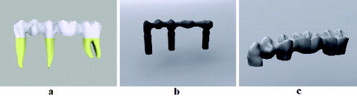
In our study, two main models were generated. Model 1 referred to a five-unit tooth-supported fixed zirconia bridge and Model 2 referred to a five-unit implant-supported fixed zirconia bridge ((a) and 1(b)). Stress distribution values and areas of stress concentration in connector regions and whole zirconia frameworks were evaluated in five areas (teeth 43–47; ISO notation) among five-unit tooth- and implant-supported zirconia prosthesis. Three-dimensional (3D) finite element stress analysis and static non-linear analysis were used in this study. Because of the boundary conditions determined for these methods, the tooth- and implant-supported models only comprised the regions of teeth 43–47 ((a)–(c)).
Figure 1. Experimental design: five-unit tooth-supported model (a); five-unit implant-supported model (b); computer modelling of teeth (c).
Modelling
Tooth numbers 43, 45 and 47 were used in our study. First, the images and size measurements of the front, side, top and bottom parts of the studied teeth were obtained from Wheeler's dental anatomy, physiology, and occlusion.[Citation29] The teeth were then modelled and scaled with 3D modelling software (Rhinoceros 4.0, McNeel North America, Seattle, WA, USA) to match these images. Thus, anatomically correct tooth models were obtained.
After the models of the teeth were created, modelling of the bone tissue surrounding the teeth was done, so that it was at least 1 cm thick. Then, for the purpose of stress analysis, bone with dimensions of 40 mm × 30 mm × 20 mm was modelled. A 2-mm thick cortical bone was created by using the offset method. The inner surface of the cortical bone was marked as spongy bone.
Next, all the modelled teeth, except teeth 44 and 46, were placed in their original positions and then extracted from the bone tissue by using the Boolean method ((a) and 2(b)). As a result, the structure of the teeth inside the bone was also modelled, and the periodontal ligament (PDL) defined to be 100 µm.[Citation30] The implant-supported model was simulated without a PDL.
Figure 2. Computer-aided models. (a) Implant slots opened on computer-aided designed bone models; (b) tooth slots opened on computer-aided designed bone models; (c) computer modelling of restorations; (d) computer modelling of zirconia frameworks and veneer sheets.
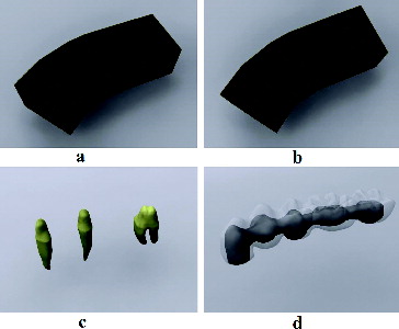
Teeth 43, 45 and 47 were prepared to a depth of 2 mm from the occlusal surface, with knife-edged margins, by using a computer program ((c)). A 100-µm thick layer of cement was modelled using the shell method from a digital preparation of the upper structures. Zirconia lower structures were then modelled using the upper section of the cement layer. The connector region was created so as to be 3 mm × 3 mm × 3 mm in size. Finally, the veneer layer was modelled using the Boolean method, by removing the zirconia lower structure from the section of the crown that was prepared ((d)).
In this study, models were obtained by placing a 4.0 mm × 11 mm Astra Tech Microthread OsseoSpeed 4.0 (Astra Zeneca Group, Sweden) dental implant into the regions numbered 43 and 45 and a 4.0 mm × 13 mm Astra Tech Microthread OsseoSpeed 4.0 (Astra Zeneca Group, Sweden) dental implant into the region numbered 47 in the implant-supported model. The models were obtained from 3D images of the implants by using the Boolean method.
The implants used in our study were three-dimensionally scanned in macro mode, using a laser scanner (NextEngine, Inc., Santa Monica, CA, USA). The obtained point cloud created from this was saved in ‘.stl’ format (surface geometry format of a 3D object without any representation of colour). These files were then opened with 3D modelling software (Rhinoceros 4.0, McNeel North America, Seattle, WA, USA), and compliance with the other sets of implants was achieved. The models made in the 3D modelling software were transferred to Algor Fempro software (ALGOR, Inc.150 Beta Drive Pittsburgh, PA, USA), maintaining their 3D coordinates.
Material properties
lists the elasticity modules and Poisson ratios of cortical bone,[Citation31] spongious bone,[Citation32] titanium,[Citation31] dentin,[Citation31,Citation33] zirconia,[Citation23] ceramic [Citation34] and zinc phosphate cement.[Citation34]
Table 1. Poisson ratio and elasticity modulus values of materials used in the study.
Installation conditions
The non-linear static analysis was completed by applying an oblique force to the prepared 3D solid models in four different installation conditions:
Installation condition 1 (canine installation): 100-N force was applied so that the buccal cusp of restoration 43 would be 30° from the buccal slope to the long axis.[Citation14–16]
Installation condition 2 (second premolar installation): 200-N force was applied so that the buccal cusp of restoration 45 would be 30° from the buccal slope to the long axis.[Citation14–16]
Installation condition 3 (second molar installation): 200-N force was applied so that the buccal cusp of restoration 47 would be 30° from the buccal slope to the long axis.[Citation14–16]
Installation condition 4 (installation of all): 100-N force was applied to restoration 43; 150-N, to restoration 44; and 200-N, to restorations 45–47, such that the buccal cusps of all these restorations would be 30° from the buccal slope to the long axis. Therefore, a total force of 850 N was applied.[Citation14–16]
Implementation of measurements
The stress measurements in connector regions and frameworks were compared and the highest stress measurement was identified.
Four different connectors used in the restorations (Models 1 and 2) were each designated different alphabet letters, as follows: A, the mesial connector between teeth 43 and 44; B, the connector between teeth 44 and 45; C, the connector between teeth 45 and 46; and D, the distal connector between teeth 46 and 47.
Numerical values obtained from the connector hubs were examined in each design of prosthesis and the highest stress values were identified. Besides the connector regions, we evaluated the highest stress values and areas of stress concentration in the zirconia frameworks of two models. Herein, the highest von Mises stress values were compared with the ultimate strength of the zirconia.
Since values obtained from the finite element stress analysis are a result of mathematical calculations without any variance, statistical analyses cannot be performed. The aim was to examine the distributions of obtained stress values in detail and interpret them.
Results and discussion
It is difficult, and sometimes even impossible, to perform stress analysis on living tissues such as bones, teeth and periodontium by using in vivo and in vitro research methods. For this reason, the stress analysis method was selected by modelling living tissues with the help of various computer programs. FEA was chosen as it is a suitable method for structures that have a complex geometry.[Citation35] 2D (two-dimensional) or 3D models can be used in the finite elements method. 2D models are considered as having only area but no volume, and therefore changes occurring in their depth are not taken into consideration. However, FEA on 3D models allows changes in any direction to be examined. In dentistry, in particular, modelled structures usually have an irregular anatomy, and so 3D models form the most realistic representations. In addition, the plane on which forces are applied is asymmetric, and so stress distribution in 3D analysis provides comparatively more accurate and realistic results.[Citation36] Ismail et al. [Citation36] in their study, compared 2D and 3D FEA using a blade implant. They reported that their 2D analysis had not reflected the usual tensile distributions and had not been sufficient when only the prime tensile distributions needed to be analysed. Therefore, we aimed at creating more realistic models and, thereby, at obtaining more realistic results.
Five-unit tooth-supported fixed zirconia bridge (Model 1)
The highest stress value in the framework in the canine installation in Model 1 was measured at the gingival neck area of restoration number 47, and connector C was the most affected connector ((a)).
Figure 3. von Mises stress values in Model 1 when the force is applied through restoration number 43 (a), number 45 (b), number 47 (c) and through all the restorations (d).
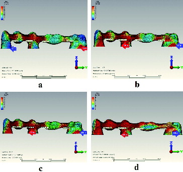
In the second premolar installation in this model, the highest stress value in the framework was measured at the mesio-gingival neck area of restoration number 45, and connector A was the most affected one ((b)). In the second molar installation, the highest stress value in the framework was measured at the mesio-gingival neck area of restoration number 45, and the connector that was most affected was connector B ((c)). When forces were applied to all the restorations in Model 1, the highest stress value (901.845 MPa) in the framework was measured at the mesio-gingival neck area of restoration number 45, with connector B being the most affected connector ((d)).
In terms of stress on the restorations, very high stress values were formed during installations (). Particularly, a stress value of 901.845 MPa falls within the ultimate strength of zirconia (900–1200 MPa). Therefore, there could be a failure of the zirconia framework in a five-unit tooth-supported fixed zirconia bridge.
Table 2. Highest stress values and areas of stress concentration in zirconia framework in Model 1.
For connector regions, the highest stress was concentrated on connector B. The lowest stress was concentrated on connector D (). Large-scale stress occurred around the connector regions of restoration number 45, as observed in most of the installations.
Table 3. Connector regions' von Mises stress values in Model 1.
Five-unit implant-supported fixed zirconia bridge (Model 2)
In the canine installation in Model 2, the highest stress value in the framework was measured at the incisal area of restoration number 43, and connector A was the most affected connector ((a)). In the second premolar installation in this model, the highest stress value in the framework was measured at the occlusal area of restoration number 45, whereas in the second molar installation, it was at the gingival neck area of restoration number 47. In the former case, connector B was the most affected connector ((b)), while in the latter case, it was connector D ((c)). When forces were applied to all the restorations in Model 2, the highest stress value in the whole framework was measured at the gingival neck area of restoration number 45, and the connector that was most affected was connector A ((d)).
Figure 4. von Mises stress values in Model 2 when the force is applied through restoration number 43 (a), number 45 (b), number 47 (c) and through all the restorations (d).
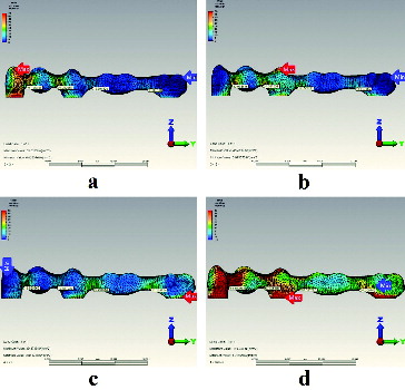
The highest stresses always occurred in the restorations in which the model had been installed. And, as can be seen in and , the stress values in Model 2 were neither as high, nor as diverse as those observed in Model 1.
Table 4. Highest stress values and areas of stress concentration in zirconia framework in Model 2.
Table 5. Connector regions' von Mises stress values in Model 2.
Final remarks
Dental restorations are exposed to different in-mouth forces during chewing and swallowing. Functional chewing forces are low forces in the range of 2–100 N.[Citation37,Citation38] It is known that the maximum bite force formed by the stomatognathic system in the posterior region is in the range of 300–800 N for the first molar teeth.[Citation37–39] Several studies claimed that zirconia shows properties adequate enough to guarantee clinical success when used in the frameworks of posterior prostheses and may be considered as a possible alternative to metal castings.[Citation40–46] For example, in fixed zirconia prostheses, Sailer et al. [Citation41] observed approximately 25% minor and 8% major chippings, with a total chipping rate of about 33%. The use of zirconia frameworks for more extended prostheses has not been sufficiently well studied.[Citation26] There are a few investigations for extended zirconia frameworks. For example, Schmitter et al. [Citation46] investigated 30 extended zirconia frameworks and 5 of them showed fracture. In another study of Schmitter et al.,[Citation47] 8 examples of 30 extended zirconia frameworks showed fracture. In our study we concluded that five-unit tooth-supported fixed zirconia bridge could show fracture at the gingival neck area of restoration number 45 under 850-N occlusal force. Because the maximum stress value in five-unit tooth-supported fixed zirconia bridge (901.845 MPa) was in the ultimate strength value of zirconia (900–1200 MPa), a fracture could be considered inevitable.
Studies have pointed to the connector area as a risk factor for fracture, and in vitro analyses of three- and five-unit fixed partial dentures have verified that cracks are initiated in the connector region.[Citation23] In our study, however, high stress values for connector regions were not within the ultimate strength value of zirconia. Molin et al. [Citation23] and Motta et al. [Citation48] found that stress values occurring in tooth-supported restoration connectors were greater in implant-supported restorations. Similarly, in our study, stress values in the tooth-supported zirconia upper structure connector were higher than those in the implant-supported upper structures.
Interestingly, in the present study, the highest stresses in Model 2 occurred in the restoration that the model was installed on. However, this situation was not the same for Model 1. This suggests that the existing PDL enabled to spread the stresses in Model 1. Due to the fact that implants osseointegrated to bone without PDL, the highest stresses always occurred in the restorations in which the model had been installed. The results we obtained in our study, are similar to those from the study of Konstantinidis et al.[Citation49]
This study, however, has some limitations. In this study, other materials except for zirconia were not evaluated in all models. Implants with different lengths and diameters could not be analysed. Only one framework design was used and there could be better ones with which the stress levels could be reduced. In our study, two types of prosthetic options were evaluated in four different ways; but more prosthetic options were not evaluated. The finite element models outlined here unfortunately cannot simulate all important features of living tissues. To achieve this, in vivo studies are needed. Using magnetic resonance imaging scans to obtain geometric information would better estimate the tissue conductivities.[Citation50]
Conclusions
The results from this study suggest that five-unit tooth-supported posterior zirconia fixed bridge prostheses are not recommended in the studied area (teeth 43–47). Additionally, when the principal stress values, which measure the compressive and tensile stresses of the bones, were taken into account, the highest values were observed in the second premolar framework region of the tooth or implant. Therefore, it could be concluded that, in five-unit fixed partial dentures, the second premolar region is the area most seriously affected in terms of stress. Moreover, the stress values in the connectors of tooth-supported fixed zirconia bridge were higher than those in the connectors of the implant-supported fixed zirconia bridge.
Acknowledgements
The authors thank Dr Emre Ari (Dicle University, Department of Mechanical Engineering) for his helpful advice on FEA.
This study was presented at the 21st TDA International Dental Congress [poster presentation P-050].
Disclosure statement
The authors deny any conflicts of interest. The authors declare that they have no competing interests.
Additional information
Funding
References
- Branemark PI, Adell R, Breine U, et al. Intra-osseous anchorage of dental prostheses. I. Experimental studies. Scand J Plast Reconstr Surg Hand Surg. 1969;3(2):81–100.
- Buser D, Mericske-Stern R, Bernard JP, et al. Long-term evaluation of non-submerged ITI implants. Part 1: 8-year life table analysis of a prospective multi-center study with 2359 implants. Clin Oral Implants Res. 1997;8:161–172.
- Christensen GJ. Ceramics vs. porcelain fused to metal crowns: give your patients a choice. J Am Dent Assoc. 1994;125:311–312, 314.
- Hansen PA, West LA. Allergic reaction following insertion of a Pd-Cu-Au fixed partial denture: a clinical report. J Prosthodont. 1997;6:144–148.
- Vult Von Steyern P, Carlson P, Nilner K. All-ceramic fixed partial dentures designed according to the DC-Zirkon technique. A 2-year clinical study. J Oral Rehabil. 2005;32:180–187.
- Piwowarczyk A, Ottl P, Lauer HC, et al. A clinical report and overview of scientific studies and clinical procedures conducted on the 3M ESPE Lava All-Ceramic System. J Prosthodont. 2005;14:39–45.
- Studart AR, Filser F, Kocher P, et al. Cyclic fatigue in water of veneer-framework composites for all-ceramic dental bridges. Dent Mater. 2007;23:177–185.
- Rismanchian M, Shafiei S, Nourbakhshian F, et al. Flexural strengths of implant-supported zirconia based bridges in posterior regions. J Adv Prosthodont. 2014;6:346–350.
- Kelly JR, Denry I. Stabilized zirconia as a structural ceramic: an overview. Dent Mater. 2008;24(3):289–298.
- Kobayashi K, Kuwajima H, Masaki T. Phase change and mechanical properties of ZrO2-Y2O3 solid electrolyte after aging. Solid State Ionics. 1981;3(4):489–495.
- Sato TMS. Transformation of yttria-doped tetragonal ZrO2 polycrystals by annealing in water. J Am Ceram Soc. 1985;68(6):356–359.
- Sato T, Shimada M. Crystalline phase-change in yttria-partially stabilized zirconia by low-temperature annealing. J Am Ceram Soc. 1984;67(10):C212–C213.
- Cales B, Stefani Y, Lilley E. Long-term in vivo and in vitro aging of a zirconia ceramic used in orthopaedy. J Biomed Mater Res. 1994;28:619–624.5
- Luo J, Ball Richard J, Stevens R. Gadolinia doped ceria/yttria stabilised zirconia electrolytes for solid oxide fuel cell applications. J Mater Sci. 2004;39(1):235–240.
- Heuer AH. Transformation toughening in ZrO2-containing ceramics. J Am Ceram Soc. 1987;70(10):689–698.
- Reidy DJ, Holmes JD, Morris MA. Preparation of a highly thermally stable titania anatase phase by addition of mixed zirconia and silica dopants. Ceram Int. 2006;32(3):235–239.
- Kingery WD, Bowen HK, Uhlmann DR. Introduction to ceramics. 2nd ed. New York (NY): Wiley; 1976.
- Petrie CS, Williams JL. Comparative evaluation of implant designs: influence of diameter, length, and taper on strains in the alveolar crest. A three-dimensional finite-element analysis. Clin Oral Implants Res. 2005;16:486–494.
- Guven S, Eratilla V, Beydemir K, et al. The evaluation of stress distributions in 3 and 5 unit dental and implant supported fixed zirconia restorations: finite element analysis. Cumhuriyet Dent J. 2015;18(2):128–140.
- Guven S, Akdogan M, Oz C, et al. Three-dimensional finite-element analysis of two ceramic inlay restorations with different cavity designs. Biotechnol Biotechnol Equip. 2015;29(3):579–585.
- Guven S, Atalay Y, Asutay F, et al. Comparison of the effects of different loading locations on stresses transferred to straight and angled implant-supported zirconia frameworks: a finite element method study. Biotechnol Biotechnol Equip. 2015;29(4):766–772.
- Guven S, Demirci F, Yavuz I, et al. Three-dimensional finite-element analysis of a single implant-supported zirconia framework and its effect on stress distribution in D4 (maxilla) and D2 (mandible) bone quality. Biotechnol Biotechnol Equip. Forthcoming 2015. DOI:10.1080/13102818.2015.1046404
- Molin MK, Onesti MP, Petersson TB, et al. Three-dimensional finite element analyses of all-ceramic posterior fixed partial dentures with different designs. Int J Prosthodont. 2007;20:89–91.
- Vult von Steyern P, Jonsson O, Nilner K. Five-year evaluation of posterior all-ceramic three-unit (In-Ceram) FPDs. Int J Prosthodont. 2001;14(4):379–384.
- Larsson C, Holm L, Lövgren N, et al. Fracture strength of four-unit Y-TZP FPD cores designed with varying connector diameter. An in-vitro study. J Oral Rehabil. 2007;34(9):702–709.
- Sorrentino R, De Simone G, Tetè S, et al. Five-year prospective clinical study of posterior three-unit zirconia-based fixed dental prostheses. Clin Oral Investig. 2012;16(3):977–985.
- Odman P, Andersson B. Procera AllCeram crowns followed for 5 to 10.5 years: a prospective clinical study. Int J Prosthodont. 2001;14:504–509.
- Sorrentino R, Galasso L, Tetè S, et al. Clinical evaluation of 209 all-ceramic single crowns cemented on natural and implant-supported abutments with different luting agents: a 6-year retrospective study. Clin Implant Dent Relat Res. 2012;14(2):184–197.
- Ash MM, Nelson N. Wheeler's dental anatomy, physiology, and occlusion. 8th ed. Philadelphia (PA): Saunders; 2002.
- Heravi F, Salari S, Tanbakuchi B, et al. Effects of crown-root angle on stress distribution in the maxillary central incisors' PDL during application of intrusive and retraction forces: a three-dimensional finite element analysis. Prog Orthod. 2013;14:26.
- Akca K, Iplikcioglu H. Finite element stress analysis of the influence of staggered versus straight placement of dental implants. Int J Oral Maxillofacial Implants. 2001;16:722–730.
- Holmes DC, Loftus JT. Influence of bone quality on stress distribution for endosseous implants. J Oral Implantol. 1997;23:104–111.
- Atmaram GH, Mohammed H. Estimation of physiologic stresses with a natural tooth considering fibrous PDL structure. J Dent Res. 1981;60:873–877.
- O'Brien WJ. Dental materials and their selection. 3rd ed. Hanover Park (IL): Quintessence Pub. Co. Inc.; 2002.
- Geng JP, Tan KB, Liu GR. Application of finite element analysis in implant dentistry: a review of the literature. J Prosthet Dent. 2001;85:585–598.
- Ismail YH, Pahountis LN, Fleming JF. Comparison of two-dimensional and three-dimensional finite element analysis of a blade implant. Int J Oral Implantol. 1987;4:25–31.
- Bates JF, Stafford GD, Harrison A. Masticatory function – a review of the literature. 1. The form of the masticatory cycle. J Oral Rehabil. 1975;2:281–301.
- Richter EJ. In vivo vertical forces on implants. Int J Oral Maxillofacial Implants. 1995;10:99–108.
- Gibbs CH, Mahan PE, Mauderli A, et al. Limits of human bite strength. J Prosthet Dent. 1986;56:226–229.
- Tsumita M, Kokubo Y, Ohkubo C, et al. Clinical evaluation of posterior all-ceramic FPDs (Cercon): a prospective clinical pilot study. J Prosthodont Res. 2010;54:102–105.
- Sailer I, Gottnerb J, Kanelb S, et al. Randomized controlled clinical trial of zirconia-ceramic and metal-ceramic posterior fixed dental prostheses: a 3-year follow-up. Int J Prosthodont. 2009;22:553–560.
- Sadan A, Blatz MB, Lang B. Clinical considerations for densely sintered alumina and zirconia restorations: part 1. Int J Periodontics Restorative Dent. 2005;25:213–219.
- Sadan A, Blatz MB, Lang B. Clinical considerations for densely sintered alumina and zirconia restorations: part 2. Int J Periodontics Restorative Dent. 2005;25:343–349.
- Eschbach S, Wolfart S, Bohlsen F, et al. Clinical evaluation of all-ceramic posterior three-unit FDPs made of In-Ceram zirconia. Int J Prosthodont. 2009;22:490–492.
- Beuer F, Edelhoff D, Gernet W, et al. Three-year clinical prospective evaluation of zirconia-based posterior fixed dental prostheses (FDPs). Clin Oral Investig. 2009;13:445–451.
- Schmitter M, Mussotter K, Rammelsberg P, et al. Clinical performance of extended zirconia frameworks for fixed dental prostheses: two-year results. J Oral Rehabil. 2009;36(8):610–615.
- Schmitter M, Mussotter K, Rammelsberg P, et al. Clinical performance of long-span zirconia frameworks for fixed dental prostheses: 5-year results. J Oral Rehabil. 2012;39(7):552–557.
- Motta AB, Pereira LC, da Cunha AR, et al. The influence of the loading mode on the stress distribution on the connector region of metal-ceramic and all-ceramic fixed partial denture. Artif Organs. 2008;32(4):283–291.
- Konstantinidis IK, Jacoby S, Rädel M, et al. Prospective evaluation of zirconia based tooth- and implant-supported fixed dental prostheses: 3-year results. J Dent. 2015;43(1):87–93.
- Yan Y, Nunez PL, Hart RT. Finite-element model of the human head: scalp potentials due to dipole sources. Med Biol Eng Comput. 1991;29(5):475–481.