
ABSTRACT
In this work, we present a novel electroporator which is capable of generating single and bursts of high power (3 kV, 60 A) square wave pulses of variable duration (100 ns to 1 ms) with predefined repetition frequency (1 Hz to 3.5 MHz). The proposed synchronized crowbar implementation ensures a constant pulse rise and fall times, which are independent from the load, thus highly relevant in electroporation. The electroporator was successfully tested for the inactivation of the human pathogen Candida albicans. The device is compatible with standard commercial electroporation cuvettes.
Introduction
The application of high-voltage pulses to generate an electric field across a biological membrane, which causes lipid rearrangements (pore formation), is termed electroporation or electro-permeabilization.[Citation1,Citation2] The extent of the effect and the effect itself can be temporary or non-reversible depending on the electric field strength, number of pulses, pulse duration and other pulse parameters.[Citation3] The effect of the shape of the high-voltage pulse on the permeabilization efficacy has been a topic of multiple experimental and theoretical studies.[Citation4–6] Subsequently, a variety of the electroporation protocols have been developed and reported for various biotechnological applications.[Citation7] For example, for reversible electroporation (delivery of drug or other molecules into cells) pulses in the range of 1 kV/cm (hundreds of microseconds to milliseconds) are usually used.[Citation7,Citation8] For larger molecules or non-reversible electroporation, the intensity of the electric field may be increased from several kV/cm to tens of kV/cm.[Citation9] In each case, development of high-voltage generators (electroporators) which are capable of delivering adjustable energy pulses to the biological loads is required.
In our previous studies,[Citation10,Citation11] we have presented electroporators which cover the micro–millisecond pulse range and are capable of generating pulsed electric fields up to 10 kV/cm. However, recent studies of the electroporation pulse strength–duration space have shown that additional intracellular effects are expected in the submicrosecond electroporation range.[Citation12] It was shown that the introduction of short high-power pulses results in the delivery of only microjoules of energy due to the brief duration and, therefore, the treatment is predominantly non-thermal.[Citation13] Nevertheless, the transient permeability of the plasma membrane and the intracellular membranes, translocation of anionic lipids from the inner layer to the outer layer of the membrane is still achievable.[Citation13,Citation14] At the same time, the submicrosecond electroporation range is the least studied range and a deeper understanding of the individual pore formation process is required, which will allow better control and optimization of the electroporation protocols and, thus, the refinement of the biotechnological and biomedical methods.[Citation13]
One of the main reasons why the submicrosecond range is poorly addressed is the lack of available implementations of the high-power electroporators, while other electroporation ranges are well covered.[Citation15] In order to generate nanosecond range pulses, Blumlein-type or other coaxial transmission line-based generator implementations are typically used.[Citation16,Citation17] For the micro–millisecond range, insulated-gate bipolar transistor (IGBT) or metal–oxide–semiconductor field-effect transistor (MOSFET) switch-based circuit topologies are applied.[Citation15] However, the submicrosecond electroporation range requires electric field strengths in the range of several tens of kV/cm, which severely limits the array of possible high-power switches. The switches that feature the breakdown voltage in the range of 3–4 kV are, as a rule, slow and not suitable to form nanosecond range pulses. Custom-made array MOSFET modules can be applied but they are limited by the maximum repetition frequency and the high loads due to the characteristic tail current which occurs in low-current applications.[Citation18] As a result, the submicrosecond electroporator implementations are frequently implemented as 1-kV range devices and are compatible with microelectrodes to achieve high electric field, while commercial cuvettes are hardly applicable due to the minimum gap of 1 mm.[Citation1,Citation19–21] The generation of higher voltage pulses is complicated by the occurring oscillations, problems of the synchronization of the switches or the load matching.[Citation22–24]
In this work, we present a novel flexible electroporator which addresses all the requirements discussed above. It is suitable for the study of electroporation in the least investigated electric field strength–duration range. The device was applied for in vitro inactivation of the human pathogen Candida albicans.
Materials and methods
Prototyping
The crucial part of the electroporator is the pulse-forming circuit. Our proposed device is based on isolated precision half-bridge drivers ADUM4223CRWZ (Analog Devices Inc., Norwood, MA, USA) and silicon carbide power MOSFETs C2M0080120D (Cree Inc., Durham, NC, USA). The power circuit and the pulse transmission line were chemically etched on an FR-4 double-sided copper board (Mega Electronics, Cambridge, UK). The 3-kV switching voltage supply MS3P/C (Spellman High Voltage Electronics Corp., Hauppauge, NY, USA) was used as the high-voltage source.
The generated pulse was measured using the 1:100 probe and a DPO4034 digital oscilloscope (Tektronix, Beaverton, OR, USA). The influence of the crowbar circuit was investigated by testing the generator performance using various resistive loads with and without the crowbar. The maximum repetition frequency of the pulses was experimentally determined as a mean of five measurements.
Biological cells
The electroporator was tested for in vitro inactivation of the human pathogen Candida albicans using electroporation. C. albicans was isolated from nail specimens in the Laboratory of Microbiology at the Centre of Laboratory Medicine, Vilnius University Hospital, Santariškių Clinics and identified by Vitek® 2 systems (bioMérieux, Marcy-l'Étoile, France). The strain was maintained on Sabouraud dextrose agar (SDA; Liofilchem, Roseto degli Abruzzi, Italy) slants at 28 °C. The suspensions for the treatment were prepared by gently scraping the culture surface with a sterile glass rod and inoculating the cells into sterile deionized water. C. albicans cell density for each solution was OD610 = 0.2. The suspensions were incubated overnight. Aliquot samples (80 µL) were used for pulsed electric field (PEF) treatment. A burst of ten 30 kV/cm (10 Hz) 100 µs electrical pulses was applied. After PEF treatment, 3 μL samples were pipetted into 1 mL sterile distilled water and vortexed. Additional dilution by a factor of 100 was performed for each sample. Then, 100 μL samples were inoculated onto SDA Petri dishes. The cells were incubated at 28 °C for 72 h. After incubation, the number of viable cells was evaluated by calculation of the number of the colony-forming units and was expressed as a percentage in respect to the control sample (without PEF treatment).
Results and discussion
Design of the high-frequency electroporator
Estimation of the pulse generator parameters
In order to develop a flexible pulsed power device for electroporation of biological cells, the required parameters for the output of the device must be determined. Due to the transdisciplinary nature of the scientific field, the selection of the parameters is influenced by the biological processes that are induced in biological objects in high electric fields. Therefore, the amplitude, duration, repetition frequency and other output pulse parameters are selected in terms of their applicability in the experiments.
As already mentioned above, the high-power submicrosecond pulses are attracting strong scientific interest due to the primarily non-thermal effect. At the same time, the microsecond range (1 µs to 1 ms) is the most widely used. The majority of electroporation protocols are designed for microsecond-range devices, while millisecond low-voltage pulses are rarely applied. Therefore, our aim was to develop a device that is capable of generating both microsecond and submicrosecond pulses to cover a wider array of electric field induced experimental applications. However, the high pulse duration flexibility sets a requirement for a high-voltage support in the range of at least 2–3 kV (20–30 kV/cm in a 1 mm gap cuvette). Moreover, since the repetition rate of the pulses may influence the efficacy of the treatment, capability to alter the pulse repetition rate in a broad range must be introduced. Based on these assumptions, the parameters for the electroporator were selected. They are summarized in
Table 1. Selected parameters for the electroporator.
The maximum pulsed current value was limited to 60 A for the support of the 50 Ω load (at maximum voltage). However, high-energy pulses are rarely used because of the Joule heating which takes place due to the high current flow. Therefore, high impedance buffers are preferable and the device must be capable of generating electrical pulses of identical form independent of the buffer type, which is relevant in electroporation experiments.
Development of the pulse-forming circuit
Taking into account the determined requirements, the pulse-forming was limited to the high-frequency MOSFET devices with high dV/dt. The IGBTs, relays or the transmission line implementations have frequency, rise/fall time or current/voltage handling limitations. It was considered advantageous to use the series connected array of the 1.2 kV breakdown voltage switches for the high-voltage handling support. The discrete modules featuring higher voltages and power are slower and are, thus, disadvantageous for the implementation of the high-frequency electroporator. The simplified circuit of the high-frequency electroporator device is shown in
Figure 1. Simplified schema of the high-frequency electroporator.
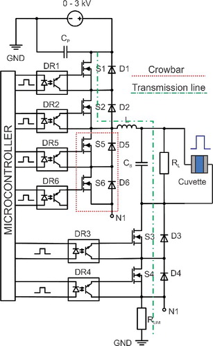
As seen in , the circuit features six switches. The capacitor array is used for the energy storage. The S1–S4 switches are employed to form the square wave pulses. The snubber diodes D1–D4 are introduced to protect the switch from the reverse voltage. The RC snubber circuits are introduced in parallel to each switch (not shown in the circuit) for the purpose of MOSFET synchronization. Optically decoupled driving circuits (DR1–DR4) are synchronized and control the MOSFETs. For optical decoupling, the ADUM4223CRWZ drivers were used. The controlled crowbar circuit, which is synchronized with S3 and S4, was implemented to achieve a short pulse fall time independent of the load. The Cs and L are introduced in the circuit diagram to highlight the influence of the stray inductance and contact capacitance. In our case, the stray inductance was in the range of 1.5 µH ± 10%, while the Cs was 50 pF ± 10%.
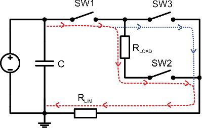
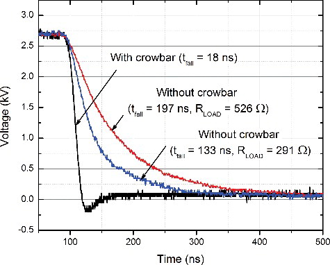
The simplified equivalent circuit of the proposed pulse-forming circuit is shown in . The S1 and S2 were simplified to SW1, S3 and S4 to SW2 and the S5 and S6 to SW3, respectively. The load (including cuvette) was approximated as resistor RLOAD. When the SW1 and SW2 are turned on, high voltage is applied to the load. The current contour is shown as a dashed line. The rise time is dependent on the switching characteristics of the switch and the parasitic parameters (stray inductance and capacitance) of the circuit. The maximum current in case of RLOAD = 0 is limited by the RLIM. When the switches (SW1 and SW2) are being turned off to end the electric pulse, the SW3 is being turned on to create a second path for the high current flow (dotted line). As a result, the fall time is dependent only on the type of the switches that were used and the parasitic parameters of the circuit. Without the synchronized crowbar circuit (SW3), the characteristic tail dependent on the load would appear and, thus, it would be impossible to generate a submicrosecond pulse with a high impedance buffer.
Figure 2. Simplified equivalent circuit of the generator.
A photograph of the board and the prototype is shown in . The device features a compact design (18 cm × 29 cm × 22 cm). The shortest output pulse waveform is shown in . As seen in figure, the shortest pulse duration (measured at 50% of Umax) is 90% ± 10% ns. The minimum pulse duration is limited by the MOSFET switching characteristics and the parasitic parameters of the circuit. The rise and fall times (10%–90% of Umax) are < 30 ns. The proposed synchronized crowbar circuit ensured fast voltage switching. The influence of the crowbar circuit was investigated experimentally and the results are presented in . As seen in figure, without the crowbar circuit, the pulse fall time depends on the load impedance, which is disadvantageous in electroporation. Our proposed circuit allows ensuring an identical electric field treatment intensity independent of the buffer type.
Figure 3. Photograph of the prototype's board and enclosure.
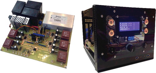
Figure 4. Waveform of the shortest electrical pulse generated by the electroporator.
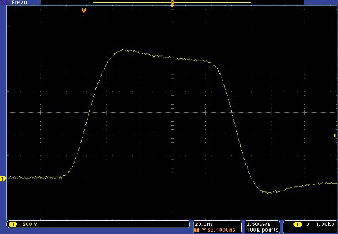
Figure 5. Dependence of the generated electrical pulse fall time on the load.
The maximum pulse repetition frequency of the device was tested. It was determined that a maximum repetition frequency of 3.5 MHz could be achieved. The 3.5 MHz pulse burst is shown in . The maximum pulse repetition frequency is highly influenced by the switch type. In our case, it was CREE C2M0080120D. The switching dynamics can be investigated in advance using the methodology proposed by Ahmed et al.[Citation25]
Figure 6. High-frequency burst of 100 ns pulses generated by the developed electroporator.
It was experimentally confirmed that the resulting high-frequency electroporator is capable of delivering adjustable 0–3 kV, 0–60 A pulses with a predefined frequency (1 Hz to 3.5 MHz). The duration of the pulse can be varied in a broad range: 100 ns–1 ms.
To the best of our knowledge, there are no currently published implementations of high-frequency (MHz range), high-voltage (>2 kV) electroporation devices that are capable of generating adjustable duration square wave pulses with load-independent pulse rise and fall times. The introduction of such high-frequency devices is advantageous for the study of the submicrosecond electroporation range. Due to the capacitive properties of the cytoplasm and the dielectric relaxation, the induced transmembrane potential dependence is not trivial in the high pulse frequency range,[Citation26] while the role of the pulse repetition rate in the submicrosecond range is considered to be controversial and requires investigation. The latest studies are limited by the kHz range repetition rate pulses.[Citation27,Citation28] However, it has been shown that even alteration of the frequency in a narrow 2–30 Hz range results in changes in the bio-effects of the high electric field.[Citation28] The expansion of the study range by introduction of novel electroporators allows investigation of newly proposed concepts such as electro-desensitization [Citation27] and helps to extend the understanding of the electroporation process even further.
Experimental application
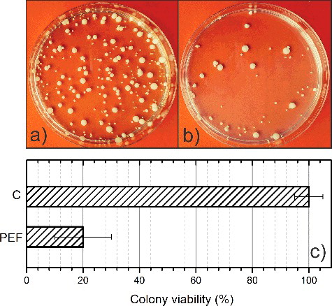
As a final step in our study, the applicability of the electroporator for in vitro inactivation of the human pathogen C. albicans was tested. The colonies before and after the treatment are shown in . The obtained results demonstrated that the applied electroporation regime can be successfully used for inactivation of C. albicans in vitro. The colony viability was reduced to 20% after electroporation. Thus, it was confirmed that the developed electroporator is suitable for biological experiments and enables a flexible parametric study of the electroporation process, which was not possible previously to such an extent.
Figure 7. Inactivation of C. albicans using electroporation: control (C) sample without PEF treatment (a); sample after PEF treatment (10 × 100 µs 30 kV/cm) (b); and colony plate counts (c).
Conclusions
This work presents a successful electroporator prototype capable of delivering adjustable 0–3 kV, 0–60 A pulses with a predefined frequency (1 Hz to 3.5 MHz). The duration of the pulse can be varied in a broad 100 ns to 1 ms range. The electroporator showed decent performance in electroporation experiments for inactivation of the human pathogen C. albicans. It was shown that a burst of ten 30 kV/cm (10 Hz) 100 µs pulses reduced the colony viability to 20% compared to the untreated samples. The proposed device enables further study of the electroporation phenomenon in the least investigated electric field strength–duration range. The determination of the equivalent pulse parameters and the biophysical processes in the cell membranes during electroporation can be investigated.
Acknowledgments
This work was performed using the joint facilities of the Vilnius Gediminas Technical University, High Magnetic Field Institute (Vilnius, Lithuania) and the Nature Research Centre, Laboratory of Biodeterioration Research (Vilnius, Lithuania).
Disclosure statement
The authors do not have any conflict of interest. All applicable international, national and/or institutional ethical guidelines were followed.
Related Research Data
References
- Denzi A, Merla C, Palego C, et al. Assessment of cytoplasm conductivity by nanosecond pulsed electric fields. IEEE Trans Biomed Eng. 2015;62:1595–1603. Available from: http://dx.doi.org/http://10.1109/TBME.2015.2399250
- Dutta D, Asmar A, Stacey M. Effects of nanosecond pulse electric fields on cellular elasticity. Micron. 2015;72:15–20. Available from: http://dx.doi.org/10.1016/j.micron.2015.01.004
- Schoenbach KH, Beebe SJ, Buescher ES. Intracellular effect of ultrashort electrical pulses. Bioelectromagnetics. 2001;22:440–448. Available from: http://dx.doi.org/10.1002/bem.71
- Kotnik T, Pucihar G, Reberšek M, et al. Role of pulse shape in cell membrane electropermeabilization. Biochim Biophys Acta Biomembr. 2003;1614:193–200. Available from: http://dx.doi.org/10.1016/S0005-2736(03)00173-1
- Faurie C, Rebersek M, Golzio M, et al. Electro-mediated gene transfer and expression are controlled by the life-time of DNA/membrane complex formation. J Gene Med. 2010;12:117–125. Available from: http://dx.doi.org/10.1002/jgm.1414
- Schoenbach KH, Pakhomov AG, Semenov I, et al. Ion transport into cells exposed to monopolar and bipolar nanosecond pulses. Bioelectrochemistry. 2015;103:44–51. Available from: http://dx.doi.org/10.1016/j.bioelechem.2014.08.015
- Pucihar G, Krmelj J, Reberšek M, et al. Equivalent pulse parameters for electroporation. IEEE Trans Biomed Eng. 2011;58:3279–3288. Available from: http://dx.doi.org/10.1109/TBME.2011.2167232
- Marty M, Sersa G, Garbay JR, et al. Electrochemotherapy – an easy, highly effective and safe treatment of cutaneous and subcutaneous metastases: Results of ESOPE (European Standard Operating Procedures of Electrochemotherapy) study. Eur J Cancer Suppl. 2006;4:3–13. Available from: http://dx.doi.org/10.1016/j.ejcsup.2006.08.002
- Xiao D, Yao C, Liu H, et al. Irreversible electroporation and apoptosis in human liver cancer cells induced by nanosecond electric pulses. Bioelectromagnetics. 2013;34:512–520. Available from: http://dx.doi.org/10.1002/bem.21796
- Grainys A, Novickij V, Novickij J. High power bipolar multilevel pulsed electroporator. Instrum Sci Technol. 2016;44(1):65–72. Available from: http://dx.doi.org/10.1080/10739149.2015.1060607
- Novickij V, Grainys A, Novickij J, et al. Compact electro-permeabilization system for controlled treatment of biological cells and cell medium conductivity change measurement. Meas Sci Rev. 2014;14:279–284. Available from: http://dx.doi.org/10.2478/msr-2014-0038
- Weaver JC, Smith KC, Esser AT, et al. A brief overview of electroporation pulse strength–duration space: a region where additional intracellular effects are expected. Bioelectrochemistry. 2012;87:236–243. Available from: http://dx.doi.org/10.1016/j.bioelechem.2012.02.007
- Kohler S, Levine ZA, Garcia-Fernandez MA, et al. Electrical analysis of cell membrane poration by an intense nanosecond pulsed electric field using an atomistic-to-continuum method. IEEE Trans Microw Theory Tech. 2015;63:2032–2040. Available from: http://dx.doi.org/10.1109/TMTT.2015.2418764
- Schoenbach K, Hargrave B, Joshi R, et al. Bioelectric effects of intense nanosecond pulses. IEEE Trans Dielectr Electr Insul. 2007;14:1088–1109. Available from: http://dx.doi.org/10.1109/TDEI.2007.4339468
- Rebersek M, Miklavcic D, Bertacchini C, et al. Cell membrane electroporation-Part 3: the equipment. IEEE Electr Insul Mag. 2014;30(3):8–18. Available from: http://dx.doi.org/10.1109/MEI.2014.6804737
- Kenaan M, Amari SE, Silve A, et al. Characterization of a 50-Ω exposure setup for high-voltage nanosecond pulsed electric field bioexperiments. IEEE Trans Biomed Eng. 2011;58:207–214. Available from: http://dx.doi.org/10.1109/TBME.2010.2081670
- Romeo S, D'Avino C, Zeni O, et al. A Blumlein-type, nanosecond pulse generator with interchangeable transmission lines for bioelectrical applications. IEEE Trans Dielectr Electr Insul. 2013;20:1224–1230. Available from: http://dx.doi.org/10.1109/TDEI.2013.6571438
- Soares RH, Barnes MJ, Kovermann J, et al. A 12 KV, 1 KHZ, pulse generator for breakdown studies of samples for CLIC RF accelerating structures. In: Vic Suller, editor. 3rd International Conference on Particle accelerator (IPAC 2012). Proceedings; 2012 May 20–25; New Orleans, LA, USA; 2012.
- Deng J, Schoenbach KH, Stephen Buescher E, et al. The effects of intense submicrosecond electrical pulses on cells. Biophys J. 2003;84:2709–2714. Available from: http://dx.doi.org/10.1016/S0006-3495(03)75076-0
- Chaney A, Sundararajan R. Simple MOSFET-based high-voltage nanosecond pulse circuit. IEEE Trans Plasma Sci. 2004;32:1919–1924. Available from: http://dx.doi.org/10.1109/TPS.2004.835966
- Sundararajan R. Nanosecond electroporation: another look. Mol Biotechnol. 2009;41:69–82. Available from: http://dx.doi.org/10.1007/s12033-008-9107-y
- Chopinet L, Batista-Napotnik T, Montigny A, et al. Nanosecond electric pulse effects on gene expression. J Membr Biol. 2013;246:851–859. Available from: http://dx.doi.org/10.1007/s00232-013-9579-y
- Sano MB, Arena CB, DeWitt MR, et al. In-vitro bipolar nano- and microsecond electro-pulse bursts for irreversible electroporation therapies. Bioelectrochemistry. 2014;100:69–79. Available from: http://dx.doi.org/10.1016/j.bioelechem.2014.07.010
- Novickij V, Grainys A, Novickij J, et al. Programmable pulsed magnetic field system for biological applications. IEEE Trans Magn. 2014;50:1–4. Available from: http://dx.doi.org/10.1109/TMAG.2014.2323336
- Ahmed MR, Todd R, Forsyth AJ. Analysis of SiC MOSFETs under hard and soft-switching. In: 2015 IEEE Energy Conversion Congress and Exposition (ECCE). Proceedings; 2015 Sep 20–24; Piscataway. QC, Canada: IEEE; 2015. p. 2231–2238.
- Zou Y, Wang C, Peng R, et al. Theoretical analyses of cellular transmembrane voltage in suspensions induced by high-frequency fields. Bioelectrochemistry. 2015;102:64–72. Available from: http://dx.doi.org/10.1016/j.bioelechem.2014.12.002
- Silve A, Guimerà Brunet A, Al-Sakere B, et al. Comparison of the effects of the repetition rate between microsecond and nanosecond pulses: electropermeabilization-induced electro-desensitization? Biochim Biophys Acta. 2014;1840:2139–2151. Available from: http://dx.doi.org/10.1016/j.bbagen.2014.02.011
- Lamberti P, Romeo S, Sannino A, et al. The role of pulse repetition rate in nsPEF-induced electroporation: a biological and numerical investigation. IEEE Trans Biomed Eng. 2015;62:2234–2243. Available from: http://dx.doi.org/10.1109/TBME.2015.2419813