
ABSTRACT
The purpose of this paper was to quickly design fixation plates for fractured proximal humerus and distal radius according to the requirements of surgical treatment. Therefore, a new method to quickly design cloverleaf plate appropriate for proximal humerus and volar plate appropriate for distal radius is put forward. First, three-dimensional (3D) reconstruction models of fractured proximal humerus and distal radius were generated based on deforming mean parametric models of proximal humerus and distal radius, respectively. Second, based on region-of-interest marked on the 3D reconstruction model of proximal humerus and distal radius, abutted surfaces of cloverleaf plate and volar plate were established, respectively. Then, parametric abutted surface was established after setting rational parameters for the surface of the cloverleaf plate. Parametric abutted surface of volar plate was established using the same method. Finally, parametric cloverleaf plate and volar plate are generated through thickening their respective parametric abutted surfaces. The parametric plates, acting as templates, accelerate and simplify the design process and therefore allow users to construct plate with editing valid parameters easily. Group of cloverleaf plates and volar plates with different sizes were generated quickly, showing that the proposed method is feasible and effective.
Introduction
Humerus and radius serve as leverages in upper limb movements. According to orthopaedic clinical and experimental study, fractures of these two types of bones (especially proximal humerus and distal radius) are very common and account for a considerable proportion of all attendances at surgical clinics. The application of fixation plates for treating these fractured bones is relatively common in computer-aided orthopaedic surgery (CAOS) [Citation1,Citation2]. More specifically, fractures are treated by operative reduction and fixation using anatomical plates which are attached to the fractured bones with locking screws [Citation3–7]. This technology gets more and more mature after long-term development and application. Obviously, fast and effect design of fixation plates is a pretty important part of CAOS. Cloverleaf plate is widely proved to be of great medical value in treating proximal humeral fracture. Esser reported good-to-excellent results of treating three-and four-part fractures of proximal humerus with a modified cloverleaf plate [Citation8]. Volar plate is a viable option for treating distal radial fracture, and the treatment effect is relatively satisfactory. Lee et al. reported effectiveness and outcome of AO titanium volar distal radius plate in the treatment of peri-articular volar rim fractures of distal radius [Citation9].
In most situations, cloverleaf plates and volar plates are mass produced in the market. In surgery, the plate which matches the fractured bone well will be selected according to surgeons’ experience. That is mainly because poor matching can cause not only low operation efficiency but also minor and major complications after operation. For different patient, both humerus and radius manifest in not only different shape parameters but also different fracture location. Although the sizes of present plates are adequately classified, clinicians have to implement adjustments (such as reshaping and trimming) for them repeatedly in surgery. Worse still, abutted surface of the plate and the bony surface cannot achieve a very good matching frequently.
Therefore, starting from regions-of-interest on three-dimensional (3D) reconstruction model of fractured bone, a new method for designing fixation plates is put forward. We all know that both bones (humerus and radius) and abutted surfaces of fixation plates are especially suitable for parameterization on account of their free-form surfaces. And many scholars have made certain achievements on parameterization for the past few years [Citation10–14]. Therefore, inspired by parametric design, parametric cloverleaf plate and volar plate are established. At last, group of cloverleaf plates and volar plates are generated. Main steps will be described in the next section.
Materials and methods
Research method
presents the work flow of designing fixation plates (cloverleaf plate and volar plate). From the picture we can see that this article can be divided into three parts. Part 1 focuses on the establishment of 3D reconstruction models of fractured bones (proximal humerus and distal radius). It should be noted that unilateral fracture is mainly studied in this article. That is, fracture of proximal humerus or distal radius occurs only on one side of a patient. Thus, medical information of non-fractured bone on the opposite side of the patient is easy to access according to symmetry of human. Thus, 3D reconstruction model of the fractured bone can be obtained after putting the measured semantic parameter values into the mean parametric bone model.
Figure 1. The work flow of designing fixation plates for fractured bones.
Part 2 describes the construction of parametric plates (cloverleaf plate for proximal humerus and parametric volar plate for distal radius). First, abutted surface of fixation plate is established based on region-of-interest marked on the reconstruction model of fractured bone. Then, parametric abutted surface of fixation plate is generated through setting rational parameters on the abutted surface. Finally, parametric plate is generated through thickening the parametric abutted surface.
Part 3 covers the generation of group of cloverleaf plates and volar plates by post-editing some semantic parameters defined on the parametric plates. This well illustrates the feasibility and validity of the proposed method.
3D reconstruction models
Reconstruction of fractured bone is the premise of designing fixation plate. There have been many reports about methods for the reconstruction [Citation14–16]. Taking distal radius as example, the reconstruction model is built based on deformation of mean parametric model of distal radius. According to body symmetry, the medical information (some related semantic parameters) of non-fractured distal radius is easy to access. Then, the measured parameter values are put into the mean parametric model. Subsequently, reconstruction model of fractured distal radius is obtained based on deformation of the mean parametric model. Based on the present studies [Citation17,Citation18], the above procedures can be easily achieved expect for the establishment of the mean parametric model. Thus, this part mainly focuses on the establishment of mean parametric model of distal radius. Here are the steps to make this work. First, 3D models of 40 radius samples are set-up. Then semantic parameters are defined and measured for every 3D model. Finally, based on statistical shape analysis, mean parametric model is generated.
Making preparation, CT images of 40 healthy adult females, scanned by 64-slice CT during 2004–2014, are collected from radiology department of the First People's Hospital of Changzhou. For the participants, the age is between 20 and 50, and the height is between 150 and 175 cm. 3D models of the collected samples are built with reverse engineering in Mimics 10.01 software.
In the parameterization of 3D model of radius, a set of parameters are defined on a referential entity (see ). First, the referential entity is created by defining geometrical elements such as feature points, axes and planes. In the referential entity, the coordinate system's origin O is located at centre point O 1 of the top-most section Sc 1 which is on the XOY plane. The bottom-most cross section of radial shaft is indicated as Sc 2 and its centre point is indicated as O 2. The centre axis of distal radius is indicated as Cs . Besides, A expresses the processus of the palmar bony ridge; B expresses the sharp point of styloid process of radius; C expresses the processus of the posterior bony ridge and Pc expresses the outermost point from O in X-axis. Then, anatomical semantic parameters that contain anatomical information are defined based on the referential entity (see for details).
Table 1. Parametric design of 3D model of distal radius.
Finally, parameter values of each 3D model from the sample set are measured. Then, based on principal component analysis, the mean parametric model of distal radius which describes the main anatomy of the sample set is generated. What we have to explain it, the process stated above is equally applicable to the establishment of the mean parametric model of proximal humerus. In the end, reconstruction models of fractured proximal humerus and distal radius are reconstructed based on mean parametric models of proximal humerus and distal radius, respectively.
Construction of parametric plates
When reconstruction model is obtained by deforming the mean parametric model, the next step is to construct fixation plate based on the reconstruction model. As we all know, surfaces of a fixation plate mainly contain abutted surface and outer surface. According to the requirement of orthopaedic operation, abutted surface must be well attached to the fractured bony surface. Especially for humerus and radius, the result of the matching directly affects the upper limb movement function recovery of patients. In order to satisfy this requirement, the abutted surface of fixation plate is taken directly from the region-of-interest of the 3D reconstruction model [Citation21–25]. Then, a fixation plate is generated through thickening the abutted surface. Meanwhile, in order to shorten production time, parametric plate which acts as template is given. In this way, group of plates with different parameter values can be quickly obtained based on the parametric plate.
The detail steps to establish abutted surface of fixation plate are as follows. First, region-of-interest is marked on bony surface of the 3D reconstruction model of fractured bone. Then, source surface is separated out from the bony surface according to boundary of the region-of-interest. Finally, a new surface, i.e. abutted surface of plate, is reconstructed through making slight smoothing process to the source surface. The generation process of abutted surface of cloverleaf plate is illustrated in (a–c). And the generation process of abutted surface of volar plate is illustrated in (a–c).
Figure 2. Construction and parameterization of abutted surface of cloverleaf plate. (a) Region-of-interest marked on bony surface of the 3D reconstruction model of proximal humerus. (b) Source surface separated from the bony surface. (c) Abutted surface. (d) Parametric abutted surface.
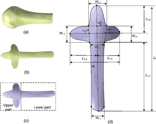
Figure 3. Construction and parameterization of abutted surface of volar plate. (a) Region-of-interest marked on bony surface of the 3D reconstruction model of distal radius. (b) Source surface separated from the bony surface. (c) Abutted surface. (d) Parametric abutted surface.
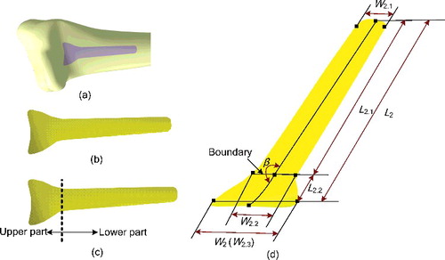
After the abutted surface of fixation plate is obtained, the next step is to achieve parametric abutted surface through setting rational semantic parameters. (d) represents parametric abutted surface of cloverleaf plate. (d) represents parametric abutted surface of volar plate. In (d) and (d), all points are feature points marked through algorithm automatically, and all internal curves are defined based on curvature of abutted surface. The defined semantic parameters are mainly about length, width and angles. To make it more clearer, the parameters shown in (d) and (d) are described in .
Table 2. Semantic parameters defined on parametric abutted surfaces.
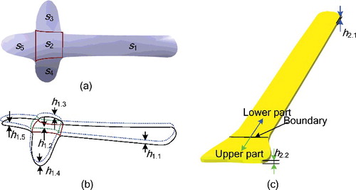
The parametric plate can be established through thickening the parametric abutted surface. First of all, the abutted surface is divided into several areas according to physiological stress. Then, based on setting expected thickness parameters on each area, parametric plate is established. (a,b) gives the generation of parametric cloverleaf plate. The divided areas of abutted surface are expressed as s 1, s 2, s 3, s 4 and s 5, respectively. And the corresponding thickness parameters are expressed as h 1.1, h 1.2, h 1.3, h 1.4 and h 1.5, respectively. Similarly, (c) gives the generation of parametric volar plate. The thicknesses of the lower part and the upper part are expressed as h 2.1 and h 2.2, respectively. By default, the initial values of all thickness parameters are set to 2 mm.
Figure 4. Area division and thickness parameter settings of parametric abutted surfaces. (a) Area division of parametric abutted surface of cloverleaf plate. (b) Thickness parameter settings of cloverleaf plate. According to expected thickness of each area, characteristic curves (dotted line) of outer surface are obtained by offsetting characteristic curves (solid lines) on the abutted surface. (c) Area division and thickness parameter settings of volar plate.
Results and discussion
In Visual Studio 2008 and CATIA V5R21, group of cloverleaf plates and volar plates are designed using the proposed method. (a) depicts initial parameter values of cloverleaf plate. (b–d) depicts cloverleaf plates generated by modifying parameter values of the parametric cloverleaf plate. (a) depicts initial parameter values of volar plate. (b,c) depicts volar plates generated by modifying parameter values of the parametric volar plate. depicts width parameter values defined on the volar plates given in (c).
Figure 5. Generation of group of cloverleaf plates. (a) Initial parameter values of parametric cloverleaf plate: L 1 = 70.0 mm; L 1.2 = L 1.3 = L 1.4 = 20.0 mm; a 1 = a 2 = a 3 = 0°; h 1.1 = h 1.2 = h 1.3 = h 1.4 = h 1.5 = 2 mm. (b–d) Group of cloverleaf plates with different parameter values. (b) Change of L 1.2, L 1.3 and L 1.4. (c) Change of L 1. (d) Change of parameter a 1, a 2 and a 3.
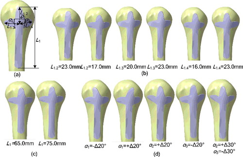
Figure 6. Generation of group of volar plates. (a) Initial values of parametric volar plate: L 2 = 50.0 mm; W 2.1 = 4.0 mm; W 2.2 = 5.5 mm; W 2.3 = 11.0 mm; h 2.1 = h 2.2 = 2 mm. (b and c) Group of volar plates with different parameter values. (b) Change of L 2. (c) Change of W 2.1, W 2.2 and W 2.3. The specific width parameter values refer to .
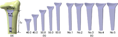
Table 3. Width parameter values of the volar plates shown in (c).
In experiments, we found that the proposed method can support designing plates with expected size. This is consistent with the potential effect of general parametric design. And thus, group of fixation plates can be designed rapidly through editing-related parameter(s) of parametric plate without starting from the beginning. This is because the parameters defined on fixation plate are flexible and convenient enough to support post-editing. It should be pointed out that parameters of human bones are relevant to such factors as sex, age, congenital factors, acquired nutrition and environmental conditions, life crafts, etc. Fixation plates designed using the proposed method can bring good surgical result for fracture patients within the sample range. Conversely, for fracture patients that are outside sample range, more extending research is needed. In addition, more accurate and reasonable parameter settings of fixation plates should be further studied, with considered not only sizes but also biomechanics, material, diameter and number of screws, etc.
Conclusions
This paper provides a scientific theory support for designing fixation plates, including cloverleaf plates for proximal humerus and volar plates for distal radius. Major characteristics are listed below: (1) mean parametric model which describes the main anatomy of upper limb within the selected sample range is established. So, the reconstruction model of one fractured bone can be easily obtained by deforming the mean parametric model; (2) abutted surface of fixation plate is constructed based on region-of-interest marked on 3D reconstruction model. This assures a pretty good matching between fixation plate and fractured bony surface. Moreover, the parametric plate accelerates and simplifies the design process, and, therefore, allows users to construct plate with editing valid parameters conveniently. The future work will focus on constraints between parametric fixation plate and fractured bone to improve serial and customized design of fixation plates.
Disclosure statement
No potential conflict of interest was reported by the authors.
Additional information
Funding
References
- Pei GX . Digital orthopaedics. Beijing: People's Medical Publishing House ; 2009.
- Yin QS , Zhang Y , Wang CT , et al. Clinical digital orthopedics: the innovation of theoretical system and clinical application. Beijing: People's Military Medical Press ; 2011.
- Gesensway D , Putnam MD , Mente PL , et al. Design and biomechanics of a plate for the distal radius. J Hand Surg. 1995;20:1021–1027.
- Rikli DA , Regazzoni P . Fractures of the distal end of the radius treated by internal fixation and early function. J Bone Joint Surg. 1996;78:589–592.
- APASeo K , Tomari S , Ito Y , et al. Treatment for distal radius fracture with acu-loc distal radius plate system. Orth Traumatol. 2010;59:93–96.
- Bigorre, N , Talha, A , Cronier, P , et al. A prospective study of a new locking plate for proximal humeral fracture. Injury. 2009;40:192–196.
- Shetty MS , Kumar MA , Kini AR . Locking distal radius plate–early results from India. J Trauma. 2011;71:1359–1363.
- Esser RD . Treatment of three-and four-part fractures of the proximal humerus with a modified cloverleaf plate. J Orth Trauma. 1994;8:15–22.1
- Lee HC , Wong YS , Chan BK , et al. Fixation of distal radius fractures using AO titanium volar distal radius plate. Hand Surgery. 2003;8:7–15.
- Langerak TR . Local parameterization of freeform shapes using freeform feature recognition. Comput-Aided Des. 2010;42:682–692.
- Nyirenda PJ , Bronsvoort WF . Numeric and curve parameters for freeform surface feature models. Comput-Aided Des. 2008;40:839–851.
- Pernot JP, Giannini F, Falcidieno B, et al. Parameterised free-form feature templates. In: Falcidieno B, Peters J, editors. Proceedings of IEEE International Conference on Shape Modeling and Applications; 2009 Jun 26–28; Beijing, China. New York (NY): IEEE; 2009. p. 140–147.
- Park BK , Bae JH , Koo BY , et al. Function-based morphing methodology for parameterizing patient-specific models of human proximal femurs. Comput-Aided Des. 2014; 51:31–38.
- Lee MK , Lee SH , Kim A , et al. The study of femoral 3D reconstruction process based on anatomical parameters using a numerical method. J Biomech Sci Eng. 2008;3:443–451.
- Yoo DJ . Three-dimensional surface reconstruction of human bone using a B-spline based interpolation approach. Comput-Aided Des. 2011;43:934–947.
- Majstorovic V , Trajanovic M , Vitkovic N , et al. Reverse engineering of human bones by using method of anatomical features. CIRP Ann-Manuf Technol. 2013;62:167–170.
- Zhong JZ . Rebuilded and modified surface model based on cross-section curves for points cloud on reverse engineering [dissertation]. Shenyang : Northeastern University; 2011.
- Chen XZ , He KJ , Chen ZM , et al. Quick construction of femoral model using surface feature parameterization. Mol Cell Biomech. 2015;12:123–146.
- Xiao L , Liu J , Li XK . Morphological classification of styloid process of radius and its clinical significance. Chinese J Clin Anat. 2010;28:507–509.
- Bao FL , Liu T , Gao W , et al. Clinical result of complicated unstable distal radial fractures by using ORIF combined with ‘Three Column Theory’. Chinese J Bone and Joint Injury. 2011;26:32–34.
- Van den Berg E , Bronsvoort WF , Vergeest JS . Freeform feature modeling: concepts and prospects. Comput Indus. 2002;49:217–233.
- Bronsvoort WF , Bidarra R , Nyirenda PJ . Developments in feature modeling. Comput-Aided Des Appl. 2006;5:655–664.
- He KJ , Wang L , Chen ZM , et al. Reconstruction and featurization of local region based on CAD surface models. Comput Int Manuf Syst. 2014;20:2360–2368.
- He KJ , Chen ZM , Zhao LH . A new method for classification and parametric representation of freeform surface feature. Int J Adv Manuf Technol. 2011;57:271–283.
- He KJ , Feng GB , Chen ZM , et al. A representation of freeform features based on characteristic curves. Scientia Sinica (Informationis). 2013;43:374–385.