
ABSTRACT
Far cortex detection during the bone-drilling process is a specific task in orthopaedic surgery. Any errors in its execution could damage the cortex wall from the inside, which often causes additional trauma even with a fatal result. Here we present some functionality enhancements of the drilling orthopaedic robot ODRO concerning the solution of the far cortex detection problem. The solution is based on software control of the thrust force applied to the bone during the drilling process. A new algorithm is created and its software realisation is provided. Experimental results are presented which verify and confirm the new functional characteristics of the robot. The risk of far cortex damage may be avoided by robot application and such precise operations may guarantee better success.
KEYWORDS:
Introduction
Most operations in orthopaedic surgery are executed manually. This often leads to various problems, such as lack of accuracy, overheating and damage of blood vessels, tendons and tissues close to the bones under manipulation. For example, Clement et al. [Citation1] report an analysis of 462 bi-cortical operations where the average error of the drill bit going out of the bone after the breakthrough is 6.31 mm.
Far cortex detection during the bone-drilling process is a specific task in orthopaedic surgery. Any errors in its execution could damage the cortex wall from the inside, which often causes additional trauma even with adverse outcomes (e.g. in spine pedicle drilling, if the spine cord is touched).
There have been developed some robotized systems aimed at performing some specific orthopaedic manipulations automatically [Citation2–5]. Some notable examples include RoboDoc (Integrated Surgical Systems, Sacramento, CA, USA), Acrobot (Imperial College London, UK) [Citation6]. MARS (MiniAture Robot for Surgery, Masor Robotics Ltd, Nesher, Haifa District, Israel, Nesher, Haifa District, Israel), CRIGOS (Compact Robot for Image Guided Orthopaedic Surgery), CASPAR (Computer Assisted Surgical Planning and Robotics System, OrtoMaquet GmbH & Co. KG, Rastatt, Germany) [Citation7,Citation8]. Relatively new ones in that area are the RIO robotic arm (MAKO Surgical Corp, Fort Lauderdale, FL, USA, 2008), iBlock (Praxim Inc., an Orthopaedic Synergy Inc. Company, Santa Clara, CA, USA, 2010) and Navio PFS (Blue Belt Technologies, Pittsburgh, PA, USA, 2012) [Citation9].
Employing robots in orthopaedic surgery allows achieving precision of surgical operations which cannot be achieved by manual execution: drill hole accuracy of 0.3–0.6 mm (CASPAR) or 0.1 mm (MARS), distance between implants and bone of 0.5 mm (RoboDoc), etc. Potential benefits of computer-assisted surgery are the reduction of invasiveness, improvement of accuracy, safety and reliability of operation, shorter time of intervention and faster return to normal activities for patients [Citation10].
The robots in surgery have very specific tasks: as the objects under manipulation are human beings, it is essential to ensure maximum reliability. Consequently, any robot used in surgical operations ought to be designed for a specific manipulation only. This approach allows achievement of maximum simplification of the robot mechanics, of the applied force level relevant to each particular case and the software and sensor system simple enough to give the surgeon efficient control of the manipulation executed by the robot.
By common definition, any device that can be called a robot must generally have the following characteristics: a mechanical system, a drive system, a sensor system and a control system, as well as interface between the device and the operator to ensure adaptation to the environment [Citation11,Citation12]. The adaptation to the environment is done by the control algorithm and its practical application by software. It must be created in such a way so as to respond to changes in the environment. This is the most important criterion which underlines the difference of a robot and a simple manipulator working with a firmly downloaded program no matter whether the environment changes or not. The far cortex detection problem is an example of such changes of the environment. To meet these requirements, we have developed a bone-drilling robot ODRO (Orthopaedic Drilling RObot) [Citation13,Citation14]. The aim of this study was to enhance the functionality of the drilling orthopaedic robot ODRO by finding a solution to the far cortex detection problem.
Materials and methods
Specimens
Bovine cortical bone, spine-column pedicle and femoral neck portions were used in the experiments. Specimens were purchased at a local butcher's shop and were kept at −5 °C before experiments.
Drilling system
The ODRO consists of a power/control block and a drilling module. The mechanical system has two degrees of freedom: translation and rotation joints (one degree of freedom each) with co-linear axes. The translation motion is driven by a linear actuator 43,000–17 (Haydon Switch & Instrument Inc., Waterbury, CT, USA) and the rotation motion, by a brushless EC-Pole 30 BLDC motor (MAXON MOTOR, Sachseln, Switzerland). The force sensor MLP-25 (Тransducer Techniques, Temecula, CA, USA) is integrated. The control system is on the basis of controller/driver TMCM-1110 (TRINAMIC, Hamburg, Germany).
The working modes are set by the surgeon by four buttons and a potentiometer in combination with a display. It gives information in real time about the duration of the drilling process and about the operation result at the end of the drilling [Citation13,Citation14]. Upon first contact with the bone, the robot determines the density. Thrust force is applied after identification in correspondence with the control algorithm taking into account that the density varies according to individual patient characteristics: age, sex and health state. The drilling automatically stops at the end, depending on the chosen working mode. During operation, messages are displayed about the correct functioning of the system, the drill-bit position and lack of sharpness [Citation15]. During the drilling, the surgeon must always keep firm contact with the bone, using some of the robot's accessories.
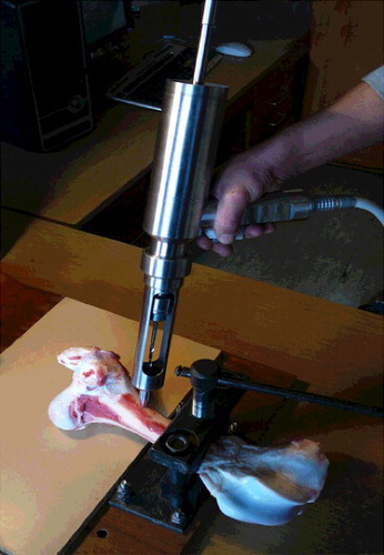
The drill bit moves only when the surgeon presses and holds the start button. If the surgeon releases it, the motion stops. By pressing the start button again, the program is continued without restarting. Such a possibility for a break leaves the main control of the operation in the hands of the surgeon. The surgeon can stop, set a new regime or keep the start button pressed until the process is finished and the drilling module goes back to its initial position automatically. Information appears on the display about the chosen regime of execution up to the current moment of time. The experimental set-up is shown in .
Figure 1. Experimental set-up.
Functionality of the ODRO
The robot works in two modes: manual and automatic [Citation13,Citation14]. In case of the former, it works like a common drilling machine; the rotation (cutting) speed is controlled by the potentiometer in the range of 0–900 r/min. The automatic mode has three sub-modes: Cortex I, drilling only through the near (first) cortex; Cortex II, drilling through both cortices (‘through-hole’) and Fixed depth, drilling to a predetermined desired depth. In Fixed depth mode, the accuracy is 0.1 mm and the working area is 100 mm.
Data analysis
The dependence of the thrust force on the time was analysed using Microsoft Excel (version 2003). The force sensor signals were input into the controller/driver TMCM-1110. The communication of the controller with a computer (PC) was achieved by a specific program created based on the C-programming language. The controller digital output was used for building the graphs in Microsoft Excel. The graphs show the thrust force deviation during the drilling process (detection of near cortex, its drilling duration, movement through the marrow, detection and eventually drilling the far cortex, etc.) and the reached maximal values.
Results and discussion
New additional functional characteristics
The functionality of the ODRO is specified by the operations that should be performed in medical practice. Continuously developing the robot, two new sub-modes are included in the Cortex II mode. They are created especially for the cases where the drill bit must only detect the far cortex wall from inside and then stop automatically.
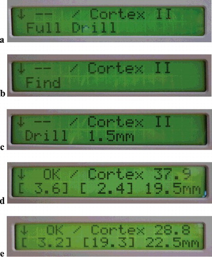
The results of working in the new sub-modes are shown in in the form of messages. They appear on the display in real time as a result of data processing by the main electronic board (printed circuit board [PCB]) placed in the control block. (a) shows the message on the display when the Cortex II (Full Drill; through-hole) mode is set. Then the robot executes drilling of both cortices and automatically stops with minimum penetration into the soft tissue. (b) shows the message on the display when the Find sub-mode of the Cortex II mode is set. As a result, the drill bit just touches the far (second) cortex after drilling the first (near) one. (c) shows the message on the display when another sub-mode, Fixed depth II, of the Cortex II mode is set. In this sub-mode, the robot drills through the near (first) cortex and partially the far (second) one, making a hole with a predetermined depth of 1.5 mm.
Figure 2. Software realization of the working modes: Full drill mode setting (a); find far cortex (Cortex II) mode setting (b); Fixed depth II mode setting (c); information displayed after Full drill end (d); information displayed after identifying the far cortex (e).
In some orthopaedic operations, it is very important not to damage the far cortex ((b)). One such instance is spine-column drilling, where the pedicle must be drilled with an error of less than 0.3 mm to avoid spinal cord injury [Citation16]. Another example is femoral neck fracture. Screws are implanted to fix bones and ensure their maximal strength which requires the drilling to be as deep as possible. Manually, the surgeon relies on sensing the far cortex, which is entirely subjective. Moreover, the cortex at that area is about 2 mm on average and the thickness is less than that of a typical femur bone (3–4 mm distance in depth). That is why operation is very difficult and dangerous due to the risk of penetration of the drill bit into the joint capsule.
Some operations need drilling of the near cortex only. But if the second cortex is 3–4 mm (like in the case of the femoral bone), then a 1.5-mm drilling of the second cortex ((c)) would ensure more stable fixation of the implant. Such a demanding precision of operation is not possible to be achieved by manual drilling.
In cases that need drilling through both cortices, the problem is undesirable drill bit penetration into the soft tissues after the breakthrough. When working in the Full Drill mode ((a)), the robot automatically stops with minimum penetration into the soft tissue, and the drill is pulled back out. The maximal drill bit penetration into the soft tissue is within a range of 0.3–1 mm.
After drilling, the result of the operation is presented on the display. The second row on the display ((d)) shows the thickness of the near cortex (Cortex I), the thickness of the far cortex (Cortex II) and the depth of the hole. By analogy, in (e), it shows the thickness of the near cortex, the distance between the end of the near cortex and the beginning of the far cortex and the depth of the hole.
Here it is noteworthy that the depth measurement, which is usually made by hand during operations, is performed automatically by the robot system at different stages of the drilling process to ensure an appropriate choice of screw implantation. The right measurements can be seen on the display in real time.
Experimental verification of the new characteristics during the drilling process
The experimental data for thrust (resistance) force measurement during bone drilling in the Cortex II Full Drill and Find second cortex mode are shown in (a,b). The drill-bit diameter is 2.8 mm and the feed rate and the cutting speed are 2 mm/s and 900 r/min, respectively. In our experiments, the final drilling time was 18.094 s in the Cortex II Full Drill mode and 17.187 s in the Find second cortex mode. The difference in the arbitrary units of time used in these two modes is due to the number of variables (in the sense of TRINAMIC) which are read during the drilling process. This reflects the differences in the scoring time. Moreover, the experiments were executed under different speeds (6 and 2 mm/s, respectively) during searching for contact with the far cortex and there were different periods of data recording.
Figure 3. Thrust force as a function of the time during execution of Cortex II Full Drill mode (a) and find second cortex mode (b).
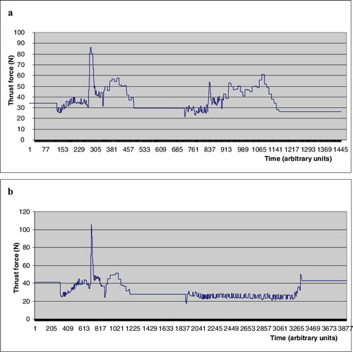
The following zones can be seen in (a): up to 300 AU, free motion until detection of contact with the near cortex (speed of 6 mm/s); 300–490 AU, drilling of the near cortex and automatically coming to a stop after its end (feed rate of 2 mm/s); 700–840 AU, searching for contact with the far cortex (feed rate of 6 mm/s); 840–1180 AU, drilling of the far cortex and automatically coming to a stop after reaching the end of the far cortex (feed rate of 2 mm/s). The zones in (a) are the following: up to 700 AU, searching for contact with the near cortex (feed rate of 6 mm/s); 700–1200 AU, drilling of the near cortex and automatically coming to a stop after the end of the near cortex (feed rate of 2 mm/s); 1900–3310 AU, searching for contact with the far cortex (feed rate of 2 mm/s); at 3310 AU, far cortex detection and automatic stop of the drilling process.
The presented robot has various advantages concerning the bone-drilling process: automatic stop after near or far cortex drilling, minimal drill bit penetration into the soft tissue after breakthrough, real-time information during operation and precise measurement of the hole depth at the end of the drilling process. Its application does not need any additional specific technical knowledge or software connected with pre-planning operation and navigation.
The functionality Find second cortex prevents from causing damage to the far cortex from the inside. This is very important for operations involving the femoral neck (in cases of fracture) and spinal column pedicles. The Fixed depth II mode gives the surgeon a choice to drill the far cortex partially or fully depending on the type of each specific trauma.
Thus, the presented robot occupies the gap between hand-held orthopedic bone drills and complex robots. The more sophisticated robots require high knowledge to work with and difficult maintenance and are very expensive. Conversely, ODRO is simple to work with, allows easy maintenance and has a low cost. At the same time, it has similar functional characteristics: for instance, its accuracy is 0.1 mm. We suggest that such a direction of development is very promising. In this context, the modified hand-held McGinley drilling machine [Citation17] deserves attention. Although it is really not a robot due to the absence of a translation drive, which leaves it with no possibility for thrust force control, it is a better step in drilling devices development and can measure the drilling depth very precisely.
Overall, because of the high precision that the bone drilling manipulation needs, it is generally considered that a satisfactory level of precision could be achieved by robot application only. That is why the term ‘intelligent bone drilling’ has been gaining popularity in recent years. In line with these high-tech developments, the International Society for Computer Assisted Orthopaedic Surgery (CAOS) [Citation18] was founded, proving the strong interest in robot applications in that field and guarantees fast development in the future.
The ODRO developed by us is part of this trend; however, although it shows some very promising features, it still has some limitations. They stem from the surgeons’ requirements for small dimensions and light weight of the devices they work with. In terms of weight, ODRO weighs about 2 kg in its current version, which is comparable to the weight of the hand drills commonly used in practice. When the shell is replaced with titanium alloy instead of stainless steel, the weight will be further reduced by 40%. Such a lighter version is expected to meet the orthopaedic surgeons’ approval.
As for the dimensions, a new version of the robot is under development, in which the motor axes will not be co-linear, but parallel. This will contribute to shortening the length. These future improvements, however, are just mechanical ones and will have no reflection on the robot functionality. Despite these limitations, the promising results obtained with the functionality enhancements of ODRO demonstrated here strongly suggest that application of such an automatic drilling procedure could be recommended, since it can help avoid the risk of far cortex damage and, thus, better guarantee the patients’ safety.
Conclusions
The present work was devoted to solving the problem of far cortex detection during the bone-drilling process using a new algorithm and its software realization on the basis of the existing ODRO. The results from the experimental tests prove the reliability of the two new additional working sub-modes created especially for the cases where the drill bit must only detect the far cortex wall from inside and then stop automatically. This is particularly important in femoral neck fracture surgery, where the implantation of screws must be done very precisely, as well as in spine-column-drilling manipulations, where spinal cord injury has to be avoided. The present work illustrates one more step in robot applications in orthopaedic surgery as part of the increasing robot assistance expected in that field in the future.
Disclosure statement
No potential conflict of interest was reported by the authors.
Additional information
Funding
References
- Clement H, Heidari N, Grechenig W, et al. Drilling, not a benign procedure: laboratory simulation of true drilling depth. Injury. 2012;43(6):950–952.
- Allotta B, Giacalone G, Rinaldi L. A hand-held drilling tool for orthopedic surgery. IEEE Trans Mechatron. 1997;2(4):218–229.
- Sugano N. Computer-assisted orthopedic surgery. J Orthop Sci. 2003;8:442–448.
- Finley DS, Nguyen NT. Surgical robotics. Curr Surg. 2005;62(2):262–272.
- Gomes P. Surgical robotics: reviewing the past, analysing the present, imagining the future. Robot Comput-Integr Manuf. 2011;27:261–266.
- Imperial college London [Internet]. London (UK): Imperial College London; c2016. Acrobot [cited 2016 Sep 7]; [about 1 screen]. Available from: http://www.imperial.ac.uk/mechatronics-in-medicine/research/acrobot/
- Faust RA, ed. 2007. Robotics in surgery: history, current and future applications. New York (NY): Nova Publishers; 2007.
- Kim KC, ed. 2013. Robotics in general surgery. New York (NY): Springer; 2013.
- Beasley RA. Medical robots: current systems and research directions. J Robotics. [Internet]. [cited 2016 Jun 21]; 2012:ID 40161. Available from: http://www.hindawi.com/journals/jr/2012/401613/
- Rau G. European BIOMED 2 program CRIGOS. Project summary. Aachen. Lehrstuhl für Biomedizinische Technik (mediTEC); c2013 [cited 2016 Aug 25]. Available from: http://www.meditec.hia.rwth-aachen.de/de/forschung/abgeschlossene-projekte/crigos/
- Scott P. 1884. The robotics revolution. New York (NY): Basil Blackwell Inc.; 1884.
- Nakano E. 1983. Introduction to robotics engineering. Tokyo: Omnsha; 1983.
- Boiadjiev T, Zagurski K, Boiadjiev G, et al. Identification of the bone structure during the automatic drilling in the orthopedic surgery. Mech Based Des Struc Mach. 2011;39(2):285–302.
- Boiadjiev G, Kastelov R, Boiadjiev T, et al. Design and performance study of an orthopaedic surgery robotized module for automatic bone drilling. Int J Med Robots. 2013;9(4):455–463.
- Boiadjiev T, Zagurski K, Boiadjiev G, et al. Automatic bone drilling in orthopedic surgery. Parameter tuning of an active force control. Int J Appl Mech Mater. 2014;532:208–211.
- Boiadjiev T, Boiadjiev G, Delchev K, et al. Eliminating of far pedicle cortex perforation by automatic spine drilling. Int J Appl Mech Mater. 2015;799–800:505–508.
- McGinley Orthopaedics [Internet]. Casper (WY): McGinley Orthopaedic Innovations [cited 2016 Jun 21]. Available from: http://www.mcginleyorthopaedicinnovations.com
- CAOS International [Internet]. Bern: International Society for Computer Assisted Orthopaedic Surgery [cited 2016 Jun 21]. c2014. Available from: http://www.caos-international.org/