
ABSTRACT
The aim of this study was to compare the stresses on cylindrical and conical dental implants under heavy bruxing forces, in D1 and D4 bone densities, using three-dimensional finite element analysis (FEA). Eight different stress models were created according to implant design (cylindrical or conical), bone density (D1 or D4) and load (1000 N, vertical or oblique). The von Mises stresses for each model were compared using FEA. The obtained results showed that D1 bone density and vertical force were associated with the least stress on the implant. Bone density was more important than implant design in stress formation. The results from the two implant types were very similar. The von Mises stress values were greater in the neck region of the implant. We suggest that the implant region should be considered firstly for less stress on the implant.
Introduction
Dental implants are routinely used to compensate for missing teeth in completely and partially edentulous patients [Citation1,Citation2]. Previous studies have noted that rehabilitation with implants is reliable, aesthetic and functional [Citation3–5]. Although the use of implants is widespread, bruxism is considered a risk factor for biological or mechanical complications of a dental implant [Citation6].
Bruxism is a diurnal or nocturnal parafunctional habit of the masticatory system occurring during sleep or while awake and is characterized by grinding with or without clenching of the teeth [Citation7,Citation8]. In the general adult population, 10% exhibit bruxism [Citation8]. Continuation of parafunctional habits can cause temporomandibular joint pain, wear on teeth, failure of restorations on natural teeth and wear on dental implants [Citation9,Citation10]. There are a number of studies relating to bruxism and implant restorations (reviewed in [Citation9]). Ninety percent of dental implant fractures are associated with chewing forces and lateral movements [Citation8,Citation11].
The aim of this study was to compare the stresses on cylindrical and conical implants under heavy bruxing forces, in D1 and D4 bone densities, using three-dimensional finite element analysis (FEA).
Materials and methods
FEA models
Eight different variations were modelled using FEA. These variations included cylindrical implant applied to D1 bone density, vertical load (model 1); cylindrical implant applied to D1 bone density, oblique load (model 2); cylindrical implant applied to D4 bone density, vertical load (model 3); cylindrical implant applied to D4 bone density, oblique load (model 4); conical implant applied to D1 bone density, vertical load (model 5); conical implant applied to D1 bone density, oblique load (model 6); conical implant applied to D4 bone density, vertical load (model 7); and conical implant applied to D4 bone density, oblique load (model 8) ( and ). The implants were applied to the mandibular first molar tooth regions and the study was based on the occlusion of the canine guidance.
Figure 1. Von Mises values in cylindrical implants: vertical (a) and oblique (b) loading on D1 bone density; vertical (c) and oblique (d) loading on D4 bone density.
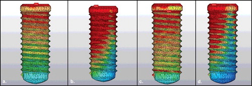
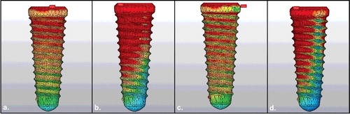
Figure 2. Von Mises values in conical implants: vertical (a) and oblique (b) loading on D1 bone density; vertical (c) and oblique (d) loading on D4 bone density.
Modelling of mandible and dental implant
A cadaver mandible was used to create the geometric model. Selection of the mandible was made from a bone with a vertical dimension of 10 mm and a width greater than 5 mm in the buccolingual direction. The mandible was scanned with cone beam tomography (ILUMA, Orthocad, CBCT, 3M Imtec, Oklahoma, USA), and 601 sections were obtained with scanning at 120 kVp, 40 s, 3.8 mA. The resulting sections were exported in DICOM 3.0 format and transferred to 3D-Doctor (Able Software Corp., MA, USA). The modelling of the mandibular bone was completed by making it a smooth surface, and sections were exported from 3D-Doctor software in .stl format. To form the trabecular bone, the border of the trabecular bone was measured as a cortical bone thickness (1.5 mm at the top, 1 mm at the buccal and lingual region) in the mandible model. D1 bone density was modelled as completely cortical bone, and D4 bone density was modelled as a 1 mm cortical and backward spongiose. To accomplish this, the .stl file was loaded into Rhinoceros 4.0 software (Robert Mcneel & Associates USA), and the offset method was used.
The large-sized implant model supplied from the ITI was scanned on the SmartOptics scanner to obtain a 3D model. After all the models were combined in the Rhinoceros software, FEA was performed ().
Figure 3. Models of dental implants and mandible used in FEA: conical implant (a); cylindrical implant (b); mandible (c).
FEA
Finally, the model was exported to ANSYS 13 Workbench software (Swanson ANSYS Inc., Canonsburg, PA, USA). A mesh was obtained automatically using the ANSYS 13 Workbench software. The mesh contained cylindrical and conical nodes and elements (cylindrical: number of nodes: 26,839, number of elements: 130,260; and conical: number of nodes: 27,494, number of elements: 133,861). The implants were rigidly attached along their entire interface and bonded in the bone to simulate 100% osseointegration.
Material properties
Identical length, diameter and screw design of Ti–6Al–4V titanium alloy cylindrical and conical dental implants were selected as the implant materials. The implants, cortical bone and cancellous bone were rendered as linearly elastic, homogeneous and isotropic. The Young's modulus, Poisson's ratio and mass density of the materials used in the analysis were taken from the literature [Citation12,Citation13] and are shown in . To assess the distribution of stresses, maximum von Mises stresses were visualized with stress contour plots.
Table 1. Young’s modulus and Poisson’s ratio of the materials used in FEA [Citation12,Citation13].
Boundary conditions and loading
Boundary conditions included constraining all three degrees of freedom at each of the nodes located in the front bevel face of condyles according to Ding et al. [Citation14]. The applied forces were static.
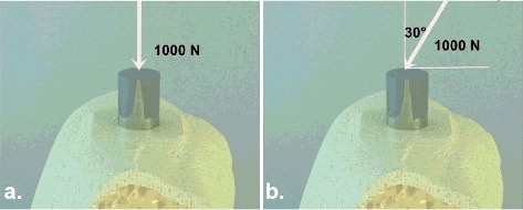
Implants were loaded at 1000 N vertically and then with a 30-degree angle onto the abutments (). The study was based on the occlusion of the canine guidance. The implants were applied to the mandibular first molar tooth regions.
Figure 4. Von Mises values in conical implants. Vertical loading (a); oblique loading (b).
Results and discussion
Few studies have evaluated implant application in bruxism patients using FEA [Citation6,Citation8,Citation9,Citation15–17]. In our study, we analysed the effect of vertical and oblique forces on the two different implant designs and two different types of surrounding bone by using FEA. The properties of the implant, D1 bone density, D4 bone density, and abutments were similar to previous studies [Citation18]. The aim of this study was to examine the effect of bone density and implant design on stress in a bruxism simulation.
FEA and limitations
In the present study, it was assumed that all the model structures were homogeneous, isotropic and had linear elasticity. However, living tissues are different [Citation19]. In addition, the lateral load, which may occur in lateral movement of the mandible during mastication, was not considered in the FEA [Citation20]. Additionally, a 100% implant–bone interface was simulated, which is impossible in clinical situations [Citation19].
Effects of implant design and bone density on implants
The design of the implant to be used and the bone density will influence the prognosis [Citation21]. The primary stability can be increased with greater bone density, which would improve the osseointegration and increase the survival probability of the dental implant [Citation22]. Five studies have shown that implant survival in type 4 bone density was decreased to a statistically significant degree [Citation23–27]. Sevimay et al. [Citation28] determined that more dense bone (D1 and D2) transmitted less force than less dense bone (D3 and D4). Increased oblique and vertical stresses above the implant and abutment cause resorption of the bone around the implant [Citation29,Citation30]. Bone density has been reported to be greater in the anterior mandibular bone and lower in the posterior maxillary bone; anterior mandibular implants have been found to be more successful [Citation22].
In our study, the obtained results were similar. The maximum von Mises stress values were as follows: model 1: 157.84 N/mm2, model 2: 887.68 N/mm2, model 3: 289.16 N/mm2, model 4: 909.04 N/mm2, model 5: 132.24 N/mm2, model 6: 828.76 N/mm2, model 7: 304.52 N/mm2 and model 8: 854.52 N/mm2 (). In the D1 bone density, the von Mises stress values occurring at the implant were less than those in the D4 bone (). In addition, the von Mises stresses were greater in the implant locator region and the implant neck region ( and ). D4 bone density increased the stress in the neck region because the force of absorption of the spongiose bone was low; the primary load is applied to the 1 mm cortical bone located in the cervical region. Therefore, bone density should be taken into account in bruxism patients, and implant planning should focus on areas with greater bone density.
Table 2. Maximum von Mises stress values in the models.
Staedt et al. [Citation31] found that conical implants had more primary stability than cylindrical implants in the ex vivo study they performed. However, Vallecillo Capilla et al. [Citation32] reported that the primary stability of cylindrical implants increased in comparison with conical implants, especially in immediate loading. In bruxism patients, the distribution of force is important in addition to the primary stability. Gehrke et al. [Citation33] noted that in the crestal region, the cylindrical implants showed a higher stress concentration (p < 0.05) when compared to the conical implants, and conical implants showed a more uniform stress distribution by photoelastic analysis. In our study, the stress was greater in cylindrical than in conical implants (). However, the results obtained with the two implant types were very similar.
Effects of vertical and oblique loading on implants
It is known that chewing forces do not merely produce vertical stresses. FEA can evaluate three separate components (vertical, horizontal, oblique) in the direction of the most strength. The angle of oblique force used in different studies is 30, 45, 60 and 75 degrees [Citation34–37]. In the present study, because of the application of a low tubercle angle prosthesis to prevent lateral forces in bruxism, oblique loading was modelled at a 30-degree angle ().
In the literature, there is no consensus on the bite force in bruxism patients. Analyses have been carried out using forces between 200–2500 N [Citation18,Citation35]. The bite force of 1000 N in a bruxism patient indicates that there is a force of 250 N in the canine tooth region according to the rule of 1:1:2 (incisor:premolar:molar) [Citation18].
In the present study, the implants were loaded with 1000 N vertically and obliquely, and it was seen that vertical force generated less stress on the implant. The stress difference particularly increased between the D1 and D4 bone density when applying vertical force (). Oblique loads also increased the stress in the cervical region ( and ). A comparison of cylindrical and conical implants revealed that similar stresses resulted in each type ( and ). However, the stress was greater in cylindrical implants ().
As a result, D1 bone density was indicated to be more important than implant design in stress formation under vertical and oblique loads. Also, the stress difference increases between D1 and D4 density under vertical load according to the oblique load.
Conclusions
Placing dental implants in areas of increased bone density could reduce the stress on the implants and potentially improve the prognosis in patients with bruxism. Prosthetic planning and biomechanics should be carefully adjusted, as vertical forces generate less stress on the implant. The von Mises results from the two implant types were very similar.
Disclosure statement
No potential conflict of interest was reported by the authors.
References
- Pjetursson BE, Thoma D, Jung R, et al. A systematic review of the survival and complication rates of implant-supported fixed dental prostheses (FDPs) after a mean observation period of at least 5 years. Clin Oral Implants Res. 2012;23(6):22–38.
- Papaspyridakos P, Mokti M, Chen CJ, et al. Implant and prosthodontic survival rates with implant fixed complete dental prostheses in the edentulous mandible after at least 5 years: a systematic review. Clin Implant Dent Relat Res. 2014;16(5):705–717.
- Esposito M, Hirsch JM, Lekholm U, et al. Biological factors contributing to failures of osseointegrated oral implants. (I). Success criteria and epidemiology. Eur J Oral Sci. 1998;106(1):527–551.
- Anitua E, Orive G, Aguirre JJ, et al. 5-year clinical experience with BTI dental implants: risk factors for implant failure. J Clin Periodontol. 2008;35(8):724–732.
- Koldsland OC, Scheie AA, Aass AM. Prevalence of implant loss and the influence of associated factors. J Periodontol. 2009;80(7):1069–1075.
- Chrcanovic BR, Kisch J, Albrektsson T, et al. Bruxism and dental implant failures: a multilevel mixed effects parametric survival analysis approach. J Oral Rehabil. 2016;43(11):813–823.
- Van der Zaag J, Lobbezoo F, Van der Avoort PG, et al. Effects of pergolide on severe sleep bruxism in a patient experiencing oral implant failure. J Oral Rehabil. 2007;34(5):317–322.
- Lobbezoo F, Van Der Zaag J, Naeije M. Bruxism: its multiple causes and its effects on dental implants - an updated review. J Oral Rehabil. 2006;33(4):293–300.
- Johansson A, Omar R, Carlsson GE. Bruxism and prosthetic treatment: a critical review. J Prosthodont Res. 2011;55(3):127–136.
- Gealh WC, Mazzo V, Barbi F, et al. Osseointegrated implant fracture: causes and treatment. J Oral Implantol. 2011;37(4):499–503.
- Rangert B, Jemt T, Jorneus L. Forces and moments on Branemark implants. Int J Oral Maxillofac Implants. 1989;4(3):241–247.
- Meijer HJ, Starmans FJ, Bosman F, et al. A comparison of three finite element models of an edentulous mandible provided with implants. J Oral Rehabil. 1993;20(2):147–157.
- Lum LB. A biomechanical rationale for the use of short implants. J Oral Implantol. 1991;17(2):126–131.
- Ding X, Zhu XH, Liao SH, et al. Implant–bone interface stress distribution in immediately loaded implants of different diameters: a three-dimensional finite element analysis. J Prosthodont. 2009;18(5):393–402.
- Achilli A, Tura F, Euwe E. Immediate/early function with tapered implants supporting maxillary and mandibular posterior fixed partial dentures: preliminary results of a prospective multicenter study. J Prosthet Dent. 2007;97(6 Suppl):S52–S58.
- Chrcanovic BR, Kisch J, Albrektsson T, et al. Bruxism and dental implant treatment complications: a retrospective comparative study of 98 bruxer patients and a matched group. Clin Oral Implants Res. 2017;28(7):1–9.
- Lobbezoo F, Brouwers JE, Cune MS, et al. Dental implants in patients with bruxing habits. J Oral Rehabil. 2006;33(2):152–159.
- Gore E, Evlioglu G. Assessment of the effect of two occlusal concepts for implant-supported fixed prostheses by finite element analysis in patients with bruxism. J Oral Implantol. 2014;40(1):68–75.
- Koca OL, Eskitascioglu G, Usumez A. Three-dimensional finite-element analysis of functional stresses in different bone locations produced by implants placed in the maxillary posterior region of the sinus floor. J Prosthet Dent. 2005;93(1):38–44.
- Kayumi S, Takayama Y, Yokoyama A, et al. Effect of bite force in occlusal adjustment of dental implants on the distribution of occlusal pressure: comparison among three bite forces in occlusal adjustment. Int J Implant Dent. 2015;1(1):14.
- Goiato MC, dos Santos DM, Santiago JF, et al. Longevity of dental implants in type IV bone: a systematic review. Int J Oral Maxillofac Surg. 2014;43(9):1108–1116.
- Fuh LJ, Huang HL, Chen CS, et al. Variations in bone density at dental implant sites in different regions of the jawbone. J Oral Rehabil. 2010;37(5):346–351.
- Alsaadi G, Quirynen M, Komarek A, et al. Impact of local and systemic factors on the incidence of oral implant failures, up to abutment connection. J Clin Periodontol. 2007;34(7):610–617.
- Hutton JE, Heath MR, Chai JY, et al. Factors related to success and failure rates at 3-year follow-up in a multicenter study of overdentures supported by Branemark implants. Int J Oral Maxillofac Implants. 1995;10(1):33–42.
- Johns RB, Jemt T, Heath MR, et al. A multicenter study of overdentures supported by Branemark implants. Int J Oral Maxillofac Implants. 1992;7(4):513–522.
- Khang W, Feldman S, Hawley CE, et al. A multi-center study comparing dual acid-etched and machined-surfaced implants in various bone qualities. J Periodontol. 2001;72(10):1384–1390.
- Rocci A, Martignoni M, Gottlow J. Immediate loading of Branemark System TiUnite and machined-surface implants in the posterior mandible: a randomized open-ended clinical trial. Clin Implant Dent Relat Res. 2003;5(1 Suppl):57–63.
- Sevimay M, Turhan F, Kilicarslan MA, et al. Three-dimensional finite element analysis of the effect of different bone quality on stress distribution in an implant-supported crown. J Prosthet Dent. 2005;93(3):227–234.
- Zanatta LC, Dib LL, Gehrke SA. Photoelastic stress analysis surrounding different implant designs under simulated static loading. J Craniofac Surg. 2014;25(3):1068–1071.
- Naert I, Duyck J, Vandamme K. Occlusal overload and bone/implant loss. Clin Oral Implants Res. 2012;23(6):95–107.
- Staedt H, Palarie V, Staedt A, et al. Primary stability of cylindrical and conical dental implants in relation to insertion torque-a comparative ex vivo evaluation. Implant Dent. 2017;26(2):250–255.
- Vallecillo Capilla M, Romero Olid Mde N, Olmedo Gaya MV, et al. Cylindrical dental implants with hydroxyapatite- and titanium plasma spray-coated surfaces: 5-year results. J Oral Implantol. 2007;33(2):59–68.
- Gehrke SA, Frugis VL, Shibli JA, et al. Influence of implant design (cylindrical and conical) in the load transfer surrounding long (13 mm) and short (7 mm) length implants: a photoelastic analysis. Open Dent J. 2016;10:522–530.
- Akca K, Iplikcioglu H. Finite element stress analysis of the influence of staggered versus straight placement of dental implants. Int J Oral Maxillofac Implants. 2001;16(5):722–730.
- Bozkaya D, Muftu S, Muftu A. Evaluation of load transfer characteristics of five different implants in compact bone at different load levels by finite elements analysis. J Prosthet Dent. 2004;92(6):523–530.
- Ciftci Y, Canay S. The effect of veneering materials on stress distribution in implant-supported fixed prosthetic restorations. Int J Oral Maxillofac Implants. 2000;15(4):571–582.
- Gharechahi J, Sharifi E, Aghdaee NA, et al. Finite element method analysis of the stress distribution to supporting tissues in a Class IV Aramany removable partial denture (Part I: the teeth and periodontal ligament). J Contemp Dent Pract. 2008;9(6):65–72.