
ABSTRACT
The purpose of this study was to experimentally measure and simulate thermal diffusion in the surrounding of specific dental drills with cylindrical and conical drills. The investigation was performed under different drilling conditions, with and without cooling and at different revolution speeds. During the experimental investigation, drilling into a polyurethane (PUR) foam block, was performed with and without cooling, and at three different revolution speeds, 800 rpm, 3,000 rpm and 5,000 rpm. Finite element method (FEM) simulation of the thermal diffusion during drilling into PUR foam was also performed. As a result, different temperature diffusion was found in the surroundings of the individual drills. During specific drilling conditions, some of the drills produce very high heat, as opposed to the other tested drills. The results from the numerical FEM analysis are consistent with the experiments, and it is evident that the shape of the drill and the drilling conditions affect the results. The measurements in our experiment were performed under specific conditions that resembled mechanical drilling and did not match the reality of drilling in dental surgery, which is very often interrupted and the drilling force is reduced by the dentist’s hand. The actual temperature is probably much lower. The finite element (FE) analysis of temperature rise during drilling can be useful for shape optimization of the drill when the target function is lower in temperature.
Introduction
During machining, heat is generated in three ways. First, plastic deformation occurs in the primary deformation zone in the shear plane. Local heating in this place creates very high temperatures; the material softens and deforms more. Then, in the secondary deformation zone, due to the deformation of the chip and when overcoming friction in the interface of the tool and chip. Finally, heat is created in the tertiary deformation zone, which is on the surface of the tool and workpiece and is given by the work which serves to overcome the friction between the machined surface and the flank face of the tool [Citation1]. Temperature and heat generation in the first two zones are mainly affected by cutting conditions, in the tertial zone is heat generation mainly influenced by wear of the tool side [Citation2,Citation3].
The emergence of the temperature rise in the bone may have fatal consequences for good osseointegration and subsequent fixation of the implant. The limit temperature for bone necrosis is 47–55 °C for about 1 min [Citation4–6]. Experimental investigation of temperatures in in vivo borehole is difficult and almost impossible. Most authors resolve this issue in vitro, on artificial or animal bones [Citation7–11].
Temperature production during surgical drilling is influenced by various parameters, such as drilling speed, drilling force [Citation12,Citation13], drill diameter, drill geometry [Citation14], as well as drill reuse [Citation15].
A review of the most common experimental techniques for temperature measurement in metal cutting processes reveals that these techniques can be classified into direct conduction, indirect radiation and metallographic methods. For testing purposes, the first two methods are the most important. Metallographic methods are based on an analysis of the microstructure of the cutting tool and they are suitable only for a limited number of cutting tools. Available methods which can be used for temperature measurement are resistance methods, thermo-couples [Citation16], and spectral radiation spectrometry [Citation3].
The drilling operation provides only a limited access for infrared measurements of the tool temperature in a blind hole. Hence, thermal measurement is necessarily restricted to the outer surfaces of the workpiece where temperature is only indirectly affected by the tool-work interaction in the borehole.
Dörr et al. [Citation17] deal with the lack of access to the tool-work contact zone by fabricating a workpiece of thickness equal to the bore-hole depth and by using an infra-red camera to measure the tool temperature at the exit of the drill. Beneath the workpiece, a 45° deviation mirror was used to direct the signal onto the camera. Coating systems were shown to reduce tool temperature.
Another possible experimental technique was invented by Pujana et al. [Citation18]. This work is otherwise focussed on monitoring chip formations during ultrasonic assisted drilling into Ti alloy. Ultrasonically assisted drilling was used into the cortical bone too [Citation19].
Oczelik and Bagci [Citation20] measured drill temperatures by inserting standard thermocouples through the coolant (oil) hole of TiAlN-coated carbide drills. The equipment employed should acquire the temperature data quickly and should work in wide temperature ranges. In this study, the temperature is measured by means of PFA Teflon Coated K (Chromega – Alomega) type thermocouples with a diameter of 127 μm. The thermocouple can take measurements up to 500 °C and its response time is 10 μs.
The key work for our purposes is a thermography measurement of the hole-drilling residual stress by Honner et al. [Citation21]. Surface infrared (IR) properties of the drilling mill and sample with strain gauge rosette of millimetre dimensions were determined in [Citation21] by the emissivity and reflectivity measurements. The dynamic surface temperature field measurement is accompanied by the strain measurement during step-by-step drilling. The temperature field is measured by the thermographic system Flir ThermaCAM SC2000 with 320 − 240 focal-plane-array of non-cooled microbolometric detectors working in the wavelength band 7.5–13 μm and with the accuracy ±2 K.
The factors that should be considered when choosing a temperature measurement method for a particular application are: temperature range; sensor robustness; temperature field disturbance by the sensor; signal type/sensitivity to noise; response time; and uncertainty. These should be weighed against the following criteria: ease of calibration; availability; cost; and size [Citation15]. One of the further parameters which influence the heat production is drill speed [Citation22].
Finite element simulations have been successfully applied to model orthogonal metal cutting processes. They have significantly reduced the simplifying assumptions of the analytical models. However, the use of FEM in metal cutting research requires a large number of input parameters which need to be determined through an extensive experimental work and mechanical property tests. These include material models for large deformation, high strain rate, temperature effects, tool-chip contact and friction models, and the separation criterion. Generally, application of finite element modelling to cutting processes involves two types of formulations; Eulerian or an updated Lagrangian. The analyses employ different material models, such as rigid-plastic or elastoplastic models. The meshes are either structured or adaptive. Chip separation criteria, friction and contact conditions at the secondary zone and coupled thermomechanical models are also considered [Citation23]. In other cases, the FEM analysis and experimental investigation of temperature during drilling into the bone with specific surgical drill was solved [Citation24–26].
Commercial implicit finite element codes such as Deform 2D–3D, MSC.Marc, Abaqus, ANSYS have instruments for solving a heat generation model. Moreover, there is the Third Wave AdvantEdge FEM software [www.thirdwavesys.com/], which is a central difference explicit dynamic and thermo-mechanically coupled Lagrangian finite element model specialized in machining operations. This software was used by Oczelik and Bagci [Citation20] for validation of experimentally measured temperature during dry drilling.
For example, Zitoune et al. used the commercial FEM system Samcef (France) [Citation27] for the fracture process modelling of long fibre composite drilling. This system employs the Virtual Crack Extension method, which is based on the fracture process and more particularly on the computation of the energy release rate. It makes it possible to measure the influence of the geometry of the cutting tool and the depth of the cut on the cutting force.
Lei et al. [Citation28] used FEM ABAQUS together with a new material constitutive equation for 1020 steel to simulate orthogonal machining with continuous chip formation. Deformation of the workpiece material is treated as elastic–viscoplastic with isotropic strain hardening, and the numerical solution accounts for coupling between plastic deformation and the temperature field, including treatment of temperature-dependent material properties. Li and Shih [Citation29] used ABAQUS to create a finite element thermal model using the inverse heat transfer method, which is applied to find the heat partition on the tool–chip contact area and convection heat transfer coefficient of the cutting fluid. Other authors [Citation30,Citation31] used their own numerical model, mostly based on FEM, to solve various problems related to the material removal problem.
The aim of the experimental measurement in the present study was to verify the thermal diffusion differences in the surrounding of four specific dental drills during drilling into a polyurethane (PUR) foam block.
Materials and methods
The PUR material was taken from Sawbones Europe AB (www.sawbones.com). Biomechanical test blocks offer uniform and consistent physical properties that eliminate the variability encountered when testing with human cadaver bone. PUR foam provides consistent and uniform material with properties in the range of human cancellous bone. Relevant mechanical properties for comparison to human cancellous bone may depend on the particular test method that is being developed. PUR foam is often used for mechanical tests based on the ASTM F-1839-08 ‘Standard Specification for Rigid Polyurethane Foam for Use as a Standard Material for Testing Orthopaedic Devices and Instruments’. They are primarily used for testing orthopaedic implants, instruments and instrumentation, and also for surgical drilling experiments [Citation24].
Experimental setup
For our specific problem, thermography by an IR camera and thermocouples measurement was used.
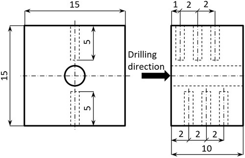
The polyurethane (PUR) block (‘artificial bone’) was 15x15x10 mm large with six holes of 5 mm depth for semiconductor thermoelements (see ). The holes for the thermocouples were distributed in a direction perpendicular to the drilling direction. These thermocouples measure thermal diffusion according to the drill depth into the PUR block. Thermocouples were fixed into the PUR block with silver thermo paste for better temperature transmission between the block material and the thermocouple.
Figure 1. PUR block with designed holes for thermocouples in the direction perpendicular to the drilling direction.
The experimental setup consisted of a surgical drilling machine (W&H) fixed in a three-axis movement CNC machine. A PUR block with installed thermocouples for detection of the temperature inside the block was fixed in a table in the same horizontal axis as the surgical drilling machine, and in the drilling direction. In front of the PUR block an IR camera (FLIR) was installed for recording the temperature at the cutting edge of experimental drills during perforating the PUR Block [Citation32].
The experiment was realized at three different rotational speeds of 800, 3,000 and 5,000 rpm. In this investigation we did not use high speed drilling [Citation33]. Every measurement combination of a drill type and a rotational speed was tested with and without cooling. For cooling, the surgical drilling machine cooling system was used. The cooling medium was water. Cooling water was applied by showering on the used drill. The axial movement of a drill is one of the important parameters [Citation34,Citation35], in our case it was in all cases 30 mm/min, which was discussed with an experienced dentist. The influence of a drill diameter and drilling force were not investigated [Citation32,Citation36].
The experimental investigation was realized on four types of drills, two cylindrical and two conical drills from two different manufacturers:
Drill no. 1610.928b Ihde Dental, cylindrical shape, diameter of 2.8 mm (),
Drill no. 1610.928b-k Dentamechanik, cylindrical shape, diameter of 2.8 mm (),
Drill no. 1610.914d Ihde Dental, conical shape, minimum diameter of 2.4 mm and 4.0 mm maximum diameter (),
Drill no. 1610.914d-k Dentamechanik, conical shape, minimum diameter of 2.45 mm and 4.0 mm maximum diameter ().
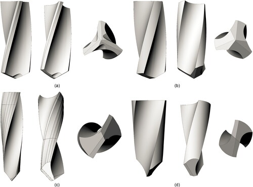
Figure 2. Different drills used in this study: Drill no. 1610.928b Ihde Dental (a), Drill no. 1610.928b-k Dentamechanik (b), Drill no. 1610.914d Ihde Dental (c), Drill no. 1610.914d-k Dentamechanik (d).
FE analysis description
The aim of the created numerical FE simulations was a heat production analysis of the drills during hole drilling into the polyurethane (PUR) foam cylinder. The concluding recommendation for the design of drills is based on the obtained results of the heat production analysis.
In the created FE simulations, four different drill geometries were analyzed. Two drills were supplied by the Ihde Dental company (1610.928b and 1610.914d) and two were supplied by Dentamechanik (1610.928b-k and 1610.914d-k). All drill geometries were sent as 3 D models with triangular surface mesh (STL format). Therefore, all drill models had to be reconstructed with the analytical surfaces. The geometry reconstruction was created in the Rhinoceros® 5 software. The maximal difference between the original triangular surface mesh and the analytical surfaces after geometry reconstruction was 0.05 mm. The reconstructed drill geometries are shown in .
The geometry of the polyurethane (PUR) foam was designed as a solid cylinder with an outer diameter of 10 mm and height of 8 mm. The shape of the hole respecting the drills surface shape was modelled in the axis of the cylinder. The depth of the hole was 5 mm.
Both the materials models, the homogeneous and the isotropic, were used in all FE analyses. All material parameters were taken from the open free database MatWeb (www.matweb.com) and the PUR foam producer’s website (www.sawbones.com) or measured [Citation37]. The properties of the material properties are described in .
Table 1. Table of material properties for used stainless alloy 1.4112 and polyurethane foam (PUR).
In the experimental measurements and FE analyses, PUR foam was used because it is primarily used as an alternative test medium for human cancellous bone. These products are not intended to replicate the mechanical properties of human bone. However, it does provide consistent and uniform material with properties in the range of human cancellous bone. Relevant mechanical properties for comparison to human cancellous bone may depend on the particular test method that is being developed. PUR foam is often used for mechanical tests based on the ASTM F-1839-08 ‘Standard Specification for Rigid Polyurethane Foam for Use as a Standard Material for Testing Orthopaedic Devices and Instruments’.
Simulation descriptions and mesh
The aims of the FE simulation were heating analyses of the drill and the PUR foam during drilling. The heating was produced by friction between the alloy drill and the PUR foam. All analyses were defined as static, coupled thermal-displacement simulations with nonlinear contact definition [Citation38].
Both parts of all the models were meshed by continuous elements with an additional degree of freedom associated with temperature. The drills were meshed by elements with global size of elements 0.2 mm. PUR foams were meshed by elements with the global size of elements of 1 mm and the contact surface inside the hole was meshed by fine mesh with the size of 0.2 mm.
Loads, interaction and boundary descriptions
The analyzed models were loaded by directed displacement and rotational boundary conditions. The FE analyses were set so that they would correspond closely with the experiments carried out. The drills were loaded by the axial displacement Uz = 0.009375 mm (corresponding with 800 rpm) and rotation angle URz = 1.57 rad (90°). The size of the displacement Uz corresponded with the drill axial movement during drill rotation about 90°. In all the analyses, drilling speed of 800 rpm was used. The bottom surface of the PUR foam part was fixed in all directions.
Loading of the drill was applied to the drill reference point, which was coupled with the upper drill surface by the kinematic coupling function. This function provides loading of boundary conditions from the mater (reference) point to the slave surface.
Simulations were modelled as a nonlinear contact task, where the contact was defined among the hole surface and the outer drill surfaces. The contact formulation was a normal hard contact, with the friction coefficient dependent on temperature (see ). The produced heating was distributed evenly to both parts. The initial temperature at the beginning of the numerical simulation in all parts was set to T = 20°.
Results
Experimental results
The data obtained from the drilling experiments are presented in for dry drilling without cooling and in for water cooled drilling. The temperature on the cutting edge of each drill and the temperature on the thermocouples positioned at 2.5 mm distance from the drilling axe were monitored. The distance of each thermocouple was 1, 2, 3, 4, 5 and 6 mm from the incoming face of the drilled specimen (the face of the rectangular parallelepiped, where the drilling process starts).
Table 2. Experimentally detected temperature of four different drills during three rotational speeds.
Table 3. Experimentally detected temperature of four different drills during three rotational speeds.
The results showed that Drill 1610.914d-k (conical Drill: Dentamechanik) cannot be used at 800 rpm together with axial movement at 30 mm/min with or without cooling. The drill stopped in the foam, so the experiment was not finished.
The least heated specimen was the conical drill no. 1610.914d IhdeDental. It was detected in both experiments with and without cooling and at all revolution speeds. In the surrounding of the drill, the maximum temperature was 50.1 °C, and at the cutting edge, it was 94.74 °C.
In both cylindrical drills, no.1610.928b IhdeDental and no.1610.928b-k Dentamechanik, very similar temperatures were detected. In the case with cooling, lower temperatures were in drill no.1610.928b-k Dentamechanik, and in the case without cooling, lower temperatures were in drill no.1610.928b IhdeDental. In drill no.1610.928b IhdeDental, a significantly low temperature was detected at the rotational speed of 5000 rpm in the surrounding of the drill in the case without cooling.
Results of original drills FE analyses
From the performed drills FE analyses, the temperature T (°C) distribution on the drills and PUR foam cylinder was obtained. Von Misses reduced stress σred (Mpa) distribution on the drills was obtained as additional results. A summary of the numerical analysis results is shown in and .
Figure 3. Figures of temperature T (°C) distribution on IhdeDental 1610.928b drill (left) and PUR foam (middle), Von Misses reduced stress σred (MPa) distribution on the drill (right).
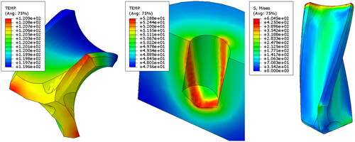
Figure 4. Figures of temperature T (°C) distribution on Dentamechanik 1610.928b-k drill (left) and PUR foam (middle), Von Misses reduced stress σred (MPa) distribution on the drill (right).
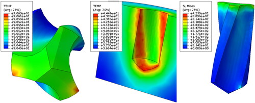
Figure 5. Figures of temperature T (°C) distribution on IhdeDental 1610.914d drill (left) and PUR foam (middle), Von Misses reduced stress σred (MPa) distribution on the drill (right).
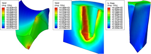
Figure 6. Figures of temperature T (°C) distribution on Dentamechanik 1610.914d-k drill (left) and PUR foam (middle), Von Misses reduced stress σred (MPa) distribution on the drill (right).
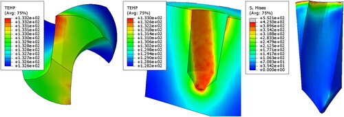
Table 4. Results from numerical analyses.
IhdeDental 1610.928b: The Temperature T and Von Misses reduced stress σred distribution on the drill are shown in . The temperature and stress distribution are uniform on the drill and the hole surface. The maximal temperature is placed on the outer side of the cutting edge. In it is shown that heating on PUR foam is produced on the cutting face together with the cutting edge on the cylinder surface. The maximal temperature is T = 120.9 °C on the drill and T = 52.9 °C on PUR foam in distance 2.5 mm from drilling axis (the same distance of thermocouples). Von Misses reduced stress distribution on the drill is uniform and its maximal value is σred = 604.5 MPa. The value of σred is greater than yield stress σY of 1.4112 alloy. It is evident that the maximal value of σred is placed only on the top drill surface, where the kinematic coupling condition was applied. The stress on the drill without the top surface is smaller than the yield stress σY.
Dentamechanik 1610.928b-k: The temperature T and Von Misses reduced stress σred distribution on the drill are shown in . The temperature and stress distribution are uniform on the drill and the hole surface. The maximal temperature is placed on the outer side of the cutting edge. On PUR foam, heating is produced on the cutting face together with the cutting edge on the cylinder surface (). The maximal temperature is T = 90.6 °C on the drill and T = 44.5 °C on PUR foam in a 2.5 mm distance from the drilling axis. Von Misses reduced stress distribution on the drill is uniform and the maximal value is σred = 290.8 MPa. The value of σred is less than yield stress of σY 1.4112 alloy. The drill Dentamechanik 1610.928b-k produces less heat than the drill IhdeDental 1610.928b by 25%.
IhdeDental 1610.914d: The temperature T and Von Misses stress σred distribution on the drill are uniform on the drill and the hole surface (). The maximal temperature is placed on the outer side of the cutting edge. illustrates that on PUR foam, heating is produced on the cutting face together with the cutting edge on the cylinder surface. The maximal temperature is T = 89.0 °C on the drill and T = 45.9 °C on PUR foam at a 2.5 mm distance from the drilling axis. Von Misses reduced stress distribution on the drill is uniform and its maximal value is σred = 336.1 MPa. The value of σred is less than the yield stress σY of 1.4112 alloy. It is evident that the drill IhdeDental 1610.914d produces the least heat of all drills. It produces 26% less heat than the drill IhdeDental 1610.928 b and 1.7% less than the drill Dentamechanik1610.928b-k.
Dentamechanik 1610.914d-k: The temperature T and Von Misses stress σred distribution on the drill shown in indicate that the temperature and stress distribution are uniform on the drill and the hole surface. The maximal temperature is placed on the outer side of the cutting edge. In it is shown that on PUR foam, heating is produced on the cutting face together with the cutting edge on the cylinder surface. The maximal temperature is T = 133.2 °C on the drill and T = 130.6 °C on PUR foam in a 2.5 mm distance from the drilling axis. Von Misses reduced stress distribution on the drill is uniform and its maximal value is σred = 552.1 MPa. The value of σred is greater than the yield stress σY of 1.4112 alloy. It is evident that the maximal value of σred is placed only on the top of the drill surface, where the kinematic coupling condition was applied. The stress on the drill without the top surface is less than the yield stress σY. The drill Dentamechanik 1610.914d-k produces the most heat of all drills. It produces 10.1% greater calculated heat than the drill IhdeDental 1610.928 b, 47.0% more than the drill Dentamechanik 1610.928b-k, and 49.6% less than the drill IhdeDental 1610.914d.
Discussion
It was found that the experimental method can be used for the measurement of the temperature distribution around the drill. The thermocouples sensors, which were placed in the drilled material, can give information about the temperature change while the drill turns. We can also describe the velocity of conduction. The maximum temperatures were found by the IR camera at the cutting edge during perforating the PUR foam. This maximum temperature is close to the maximum which is probably inside the PUR foam during drilling.
The temperature obtained by using thermocouples was less than on the drill top, but it was taken by a different measurement method. In all cases, the thermocouples were at a distance from the drill shape (drilled hole). The distance from the hole axis was the same for all thermocouples (thermocouples were closer to the drills with bigger diameter). Significant temperature differences were not found in different drill diameters used in this case.
Table 6 compares the results obtained from experimental measurements and from numerical FE analysis. The maximum temperatures at the tip of the drills at the moment of PUR foam penetration obtained by the IR camera are compared, as well as the temperatures along the drills measured by thermocouples and calculated by numerical simulation. It can be seen that the temperatures obtained by the experiment correspond to the calculated temperatures. It is therefore possible to use FE simulation for the initial temperature analysis.
Table 6. Maximal temperatures (°C) obtained from experimental measurements and FE analyses.
With the Dentamechanik 1610.914d-k conical drill, at 800 rpm and a displacement of 30 mm/min, there was a combination of cutting conditions where it was not possible to remove chips, the drill jammed, and the experiment could not be completed. The specific shape of this conical drill proved to be unsuitable in this case Numerical simulation in this case showed a significant increase in temperature.
The created FE simulations analyze the influence of the drill geometry on the heat production during drilling (friction of the drill on PUR foam). Generally, drilling is a rather complicated process, where multiple factors act (material removing, chip transport, drill geometry, drill size, cutting face cooling, etc.) [Citation4,Citation39,Citation40]. All the created FE analyses were focussed only on one of them, on the heat produced by drill friction on PUR foam. We used our experience with numerical simulation of drilling to achieve a number of experimental and numerical results [Citation38].
The FE analysis of this complex process is extremely difficult, especially when biological tissues are involved in this process (for biological tissues, it is impossible to import all necessary material properties to the FE model). Therefore, PUR foam with exactly defined material properties was used for the experimental tests and numerical simulations. In our opinion, this simplification did not influence the presented results in case of comparison of the used specific drills. The maximum temperatures estimated by the FE analysis correspond with the results obtained by the IR camera.
The measurements in our experiment were performed under specific conditions that resembled mechanical drilling and did not match the reality of drilling in dental surgery, which is very often interrupted, and the drilling force is reduced by the dentist’s hand. The actual temperature is probably much lower. The FE analysis of temperature rise during drilling can be useful for shape optimization of the drill when the target function is lower in temperature [Citation41] or for new drill shapes and function [Citation42].
Unlike just measuring the temperature around the drill [Citation43], we measured the temperature at the drill tip with an IR camera. Thus, we showed that this temperature is much higher, although it is not possible to measure inside the material, since it is not possible to rely only on thermocouples.
In our study it was shown that it is possible to simulate the formation of temperature when drilling into porous material, and to predict the suitability of the shape of the drilling tool so that the temperature did not rise above the limit of bone necrosis.
Conclusions
Experimental measurement of the drill temperature during drilling is difficult for many reasons. In our study, we experimentally measured the temperature around the drill with thermocouples and by using an IR camera during PUR foam penetration by the specific drill. In the numerical FE simulation of drilling under different cutting conditions, we achieved agreement with the experiment in determining the temperature. It is therefore possible to use numerical simulation of drilling for preliminary analysis of temperature conditions, without complex experimentation. We have shown that this methodology is suitable for assessing the shape of newly developed drills and we can reveal risk points in their shape. And finally, relatively small differences in the shape of the drill can mean large differences in temperature production.
Disclosure statement
No potential conflict of interest was reported by the authors.
Data availability statement
Data about the article are available at DOI: 10.6084/m9.figshare.14173457
Additional information
Funding
References
- Jam J, Fard VN. A novel method to determine tool-chip thermal contact conductance in machining. Mater Sci. 2011;3:8491–8501.
- Souza JVC, Kelly CA, Moreira MRV, et al. β-SI3N4 cutting tools obtaining for machining of the gray cast iron. In: Kuljanic E, editor. AMST’05 Advanced Manufacturing Systems and Technology. CISM International Centre for Mechanical Sciences (Courses and Lectures), vol. 486. Vienna: Springer; 2005.
- Davies MA, Yoon HW, Schmitz TL, et al. Calibrated thermal microscopy of the tool-chip interface in machining. J Mach Sci Technol. 2003;7(2):167–190.
- Augustin G, Davila S, Mihoci K, et al. Thermal osteonecrosis and bone drilling parameters revisited. Arch Orthop Trauma Surg. 2008;128(1):71–77.
- Augustin G, Zigman T, Davila S, et al. Cortical bone drilling and thermal osteonecrosis. Clin Biomech (Bristol, Avon). 2012;27(4):313–325.
- Udiljak T, Ciglar D, Skoric S. Investigation into bone drilling and thermal bone necrosis. Adv Prod Eng Manage. 2007;2:103–112.
- Stelzle F, Frenkel C, Riemann M, et al. The effect of load on heat production, thermal effects and expenditure of time during implant site preparation – an experimental ex vivo comparison between piezosurgery and conventional drilling. Clin Oral Impl Res. 2014;25(2):e140–e148.
- Gehrke SA, Bettach R, Taschieri S, et al. Temperature changes in cortical bone after implant site preparation using a single bur versus multiple drilling steps: an In Vitro Investigation. Clin Implant Dent Relat Res. 2015;17(4):700–707.
- Eriksson RA, Adell R. Temperatures during drilling for the placement of implants using the osseointegration technique. J Oral Maxillofac Surg. 1986;44(1):4–7.
- Hillery MT, Shuaib I. Temperature effects in the drilling of human and bovine bone. J Mater Process Technol. 1999;92–93:302–308.
- Soriano J, Garay A, Aristimuño P, et al. Effects of rotational speed, feed rate and tool type on temperatures and cutting forces when drilling bovine cortical bone. Mach Sci Technol. 2013;17(4):611–636.
- Bachus K, Rondina M, Hutchinson D. The effects of drilling force on cortical temperatures and their duration: an in vitro study. Med Eng Phys. 2000;22(10):685–691.
- MacAvelia T, Ghasempoor A, Janabi-Sharifi F. Force and torque modelling of drilling simulation for orthopaedic surgery. Comput Methods Biomech Biomed Eng. 2014;17(12):1285–1294.
- Karmani S, Lam F. The design and function of surgical drills and K-wires. Curr Orthopaed. 2004;18(6):484–490.
- Allan W, Williams ED, Kerawala CJ. Effects of repeated drill use on temperature of bone during preparation for osteosynthesis self-tapping screws. Br J Oral Maxillofac Surg. 2005;43(4):314–319.
- Komanduri R, Hou ZB. A review of the experimental techniques for the measurement of heat and temperatures generated in some manufacturing processes and tribology. Tribol Int. 2001;34(10):653–682.
- Dörr J, Mertens T, Engering G, et al. In-situ’ temperature measurement to determine the machining potential of different tool coatings. Surf Coat Technol. 2003;174–175:389–392.
- Pujana J, Rivero A, Celaya A, et al. Analysis of ultrasonic-assisted drilling of ti6al4v. Int J Mach Tools Manuf. 2009;49(6):500–508.
- Alam K, Hassan E, Bahadur I. Experimental measurements of temperatures in ultrasonically assisted drilling of cortical bone. Biotechnol Biotechnol Equip. 2015;29(4):753–757.
- Ozcelik B, Bagci E. Experimental and numerical studies on the determination of twist drill temperature in dry drilling: a new approach. Mater Des. 2006;27(10):920–927.
- Honner M, Lito P, Vantner M. Thermography analyses of the hole-drilling residual stress measuring technique. Infrared Phys Technol. 2004;45(2):131–142.
- Fialho JC, Fernandes PR, Eça L, et al. Computational hip joint simulator for wear and heat generation. J Biomech. 2007;40(11):2358–2366.
- Abukhshim NA, Mativenga PT, Sheikh MA. Heat generation and temperature prediction in metal cutting: a review and implications for high speed machining. Int J Mach Tools Manuf. 2006;46(7–8):782–800.
- Basiaga M, Paszenda Z, Szewczenko J, et al. Numerical and experimental analyses of drills used in osteosynthesis. Acta Bioeng Biomech. 2011;13(4):29–36.
- Paszenda Z, Basiaga M. FEM analysis of drills used in bone surgery. Arch Mater Sci Eng. 2009;36:103–109.
- Tu Y, Chen L, Huang C, et al. Finite element simulation of drill bit and bone thermal contact during drilling. 2008 2nd International Conference on Bioinformatic and Biomedical Engineering. 2008:1268–1271. DOI: 10.1109/ICBBE.2008.645.
- Zitoune R, Collombet F, Lachaud F, et al. Experiment-calculation comparison of the cutting conditions representative of the long fiber composite drilling phase. Compos Sci Technol. 2005;65(3–4):455–466.
- Lei S, Shin YC, Incroper FP. Thermo-mechanical modeling of orthogonal machining process by finite element analysis. Int J Mach Tools Manuf. 1999;39(5):731–750.
- Li R, Shih A. Spiral point drill temperature and stress in high-throughput drilling of titanium. Int J Mach Tools Manuf. 2007;47(12–13):2005–2017.
- Filiz S, Ozdoganlar OB. A three-dimensional model for the dynamics of microendmills including bending, torsional and axial vibrations. Precis Eng. 2011;35(1):24–37.
- Strenkowski JS, Hsieh CC, Shih AJ. An analytical finite element technique for predicting thrust force and torque in drilling. Int J Mach Tools Manuf. 2004;44(12–13):1413–1421.
- Horak Z, Dvorak K, Zarybnicka L, et al. Experimental measurements of mechanical properties of PUR foam used for testing medical devices and instruments depending on temperature. Density Strain Rate Maters. 2020;13:4560.
- Sarparast M, Ghoreishi M, Jahangirpoor T, et al. Modelling and optimisation of temperature and force behaviour in high-speed bone drilling. Biotechnol Biotechnol Equip. 2019;33(1):1616–1625.
- Sharawy M, Misch CE, Weller N, et al. Heat generation during implant drilling: the significance of motor speed. J Oral Maxillofac Surg. 2002;60(10):1160–1169.
- Aldabagh AH. The significance of motor speed on heat generation during implant drilling (experimental study on bovine bone). RDENTJ. 2009;9(2):303–306.
- Bogovič V, Svete A, Bajsić I. Effects of a drill diameter on the temperature rise in a bone during implant site preparation under clinical conditions. Proc Inst Mech Eng H. 2016;230(10):907–917.
- Mishra SK, Chowdhary R . Heat generated by dental implant drills during osteotomy-a review: heat generated by dental implant drills. J Indian Prosthodont Soc. 2014;14(2):131–143.
- Horak Z, Tichy P, Dvorak K, et al. Application of an arbitrary lagrangian–eulerian method to modelling the machining of rigid polyurethane foam. Materials. 2021;14(7):1654.
- Brisman DL. The effect of speed, pressure and time on bone temperature during the drilling of implant sites. Int J Oral Maxillofac Implants. 1996;11:35–37.
- Abbas AAS, Abou-El-Hossein K. Investigation of drill bit temperature during automatic bone drilling. IJEMM. 2018;3(4):245–250.
- Pandey RK, Panda SS. Modelling and optimization of temperature in orthopaedic drilling: an in vitro study. Acta Bioeng Biomech. 2014;16:107–116.
- Augustin G, Davila S, Udilljak T, et al. Temperature changes during cortical bone drilling with a newly designed step drill and an internally cooled drill. Int Orthop. 2012;36(7):1449–1456.
- Hou Y, Li C, Ma H, et al. An experimental research on bone drilling temperature in orthopaedic surgery. TOMSJ. 2015;9(1):178–188.