
 ?Mathematical formulae have been encoded as MathML and are displayed in this HTML version using MathJax in order to improve their display. Uncheck the box to turn MathJax off. This feature requires Javascript. Click on a formula to zoom.
Abstract
The orthopedic manipulation of bone drilling is performed during the osteosynthesis of bone fractures. It is characterized by a set of input and output parameters. The temperature in the tool-bone interaction zone is one of the most important output parameters of the drilling process. The increase in temperature above a certain threshold causes thermal osteonecrosis of bone cells and all the resulting negative consequences. This work presents a way of drill-bit upper limit temperature calculation during robotized bone drilling process. The temperature estimation and temperature calculation methodology is based on the energy conversion in the bone-robot system, preserving the overall energy balance according to the universal energy conservation law. The bone drilling is performed by using of robot ODRO. Fresh porcine femur bones are used as specimens in the experiments which validate the theoretical results. The real time temperature data during drilling are obtained using a non-contact temperature sensor. A computational approach is developed for estimating the temperature in the drilling zone on the base of the obtained data.The temperature estimation data can be used to control of the cutting condition during a robotic bone drilling process in order to obtain an optimal outcome.
Introduction
The ‘bone drilling’ manipulation is the most frequently performed one in orthopedic surgery. It is characterized by a wide set of parameters − 31 inputs and 8 outputs parameters [Citation1]. The input parameters have both individual and combined effects on output responses. The most important output parameters that characterize the manipulation’s outcome are the thermal and mechanical bone damages related to temperature and thrust force values during drilling. The maximum temperature mostly depends on two input parameters of the bone drilling process – feed rate and drill speed. Controlling these two parameters can ensure an optimal outcome in terms of avoiding thermal osteonecrosis, subsequent bone resorption (loss of bone substance), pullout strength implant reduction and fixation failure [Citation2–4]. In order to optimize the result of the bone drilling process compared to its manual (conventional) implementation, in recent years systems have been developed for its automated execution, the so-called handheld robotic bone drilling systems [Citation5–9]. The handheld robot can have a kinematic structure with axes, arranged in a straight line or in parallel lines, where the base is held by the surgeon [Citation10].
Some of them are already being implemented in surgical orthopedic practice [Citation5–7], and others are under development [Citation8,Citation9]. However, no experimental results are presented which are related to the increase in temperature in the robotic execution of bone drilling when using these systems [Citation8,Citation9]. The lack of temperature feedback during bone drilling in these systems makes it impossible to control the process in terms of controlling the temperature rise.
Many experimental researches aim to determine such input parameters combination which is able to guarantee an optimal result concerning the output parameters [Citation1,Citation11]. To find such a combination of optimal values of the input parameters is a task which is very difficult to solve in practice [Citation12], because the value of the input parameter feed rate, for example, which is optimal in terms of temperature rise, at the same time adversely affects another output parameter – for example, thrust force. Other examples include the following dependencies:
increasing the feed rate reduces the drilling time interval and therefore the duration of heating, so the risk of thermal osteonecrosis becomes less [Citation13,Citation14];
increasing in feed rate causes an increase in the thrust force and the risk of traumatic osteonecrosis becomes higher [Citation15,Citation16];
increasing in drill speed leads to temperature increase [Citation13,Citation17,Citation18], so the risk of thermal osteonecrosis becomes bigger; experimental results reveal a proportional connection between temperature and drilling speed [Citation18];
increasing in drill speed leads to a decrease in the thrust force [Citation15,Citation16] and the risk of traumatic osteonecrosis becomes smaller.
The complex relationships between the drilling conditions, drill-bit geometry, and bone characteristics present a major challenge in determining the optimal set of bone drilling parameters to minimize thermal and traumatic bone damage. Moreover, the large number of significant drilling parameters makes the study and optimization of the bone drilling only through experiments impractical [Citation19]. Several thermo-mechanical models have been published to predict heat generation, the temperature rise and thermal injury in bone during a drilling process [Citation19–22]. The presented thermal models are used for sensitivity analysis in order to reveal the effect of input parameters on output parameters and for parametric study to determine optimal cutting conditions and drill bit geometries, which reduce thermal damage in the bone drilling process simulation. The accuracy of the models is usually verified by experimental temperature data obtained from thermocouples located at a certain distance from the drilling zone in pre-drilled holes in the bone samples. However, these models cannot be used for real-time bone drilling control due to the amount of computation required.
From everything said so far, the following conclusion can be drawn: in order to achieve an optimal result of the manipulation, the thrust force and the temperature during drilling should be controlled. This can be achieved by force and temperature feedbacks. In practice, this can only be achieved under the conditions of the robotic bone drilling process [Citation12]. The work presents a way for drill-bit upper limit temperature calculation which allows to implement temperature feedback during the robotic manipulation.
Materials and methods
Theoretical background
The temperature estimation and temperature feedback methodology is based on the energy conversion in the bone-robot system, preserving the overall energy balance according to the universal energy conservation law.
The method serves to model the dynamics of hybrid systems, i.e. such systems that receive, transform and release energy of different types - for example, electrical, mechanical, and thermal, etc. The energy interactions are described with terms appropriate for this type which correspond to certain mathematical symbols. These symbols are considered the ‘base variables’ of a given energy space. Its physical dimension is given and then the corresponding dimension in terms of the basic units in the SI system - mass M, length L, time T and Ampere I. Historically, each pair of basis variables has been defined by the common terms ‘Across’ and ‘Through’ [Citation23]. Common to the bases of all spaces is the property that the product of their basis variables has power dimension [L2M/T3], i.e. the change in the energy described by them per unit of time. In the further considerations, we will limit ourselves to the energy interaction between mechanical and thermal phenomena, and the energy converted in this process can be considered as external – for example, brought in by the robot’s engines. The parameters of these energy descriptions, as well as the corresponding bases, are shown in .
Table 1. Table of the energy bases.
Mathematical model
In bone drilling process, a relatively much amount of work, done by mechanical subsystem of the robot, is converted directly into heat in the ‘bone - drill bit’ area [Citation1]. As a result the temperature of the drill bit and the bone rise simultaneously. During drilling, the drill heats up much faster than the bone - due to its smaller (from 2.5 to 3 times) specific heat capacity, and the maximum temperature is reached at the upper cutting edge of the drill [Citation24].
Before starting the drilling, the orthopedic drill is in a state of thermal equilibrium, i.e. the temperature in the separate areas of the drill bit is the same. After starting the drilling, a temperature difference occurs between the tip of the bit (which is heated) and the rest of the bit, and the drill bit goes into a new state. In a body that is not in temperature equilibrium (there is a different temperature in different areas of the body), heat energy is transferring. Such a process is called heat conduction. A quantitative characteristic of thermal conductivity is the heat flow – a vector with a direction of heat transfer and a magnitude determining the intensity of heat transfer.
After starting the drilling process the total heat flow that occurs due to the temperature difference between the tip of the drill (which is heated) and the part of the drill that is outside the bone, as well as between the drill and the bone, is:
(1)
(1)
where
is the magnitude of the outgoing heat flow through the drill, directed axially from its bone-cutting tip to the shank clamped in the chuck of the machine;
e is the magnitude of the outgoing heat flow along the axis, realized by the chips;
is the magnitude of the heat flow from the surface of the drill through the walls of the hole drilled so far to the bone, which is 0 for the part of the drill that is outside the bone;
is the magnitude of the heat flow from the drill surface to the atmosphere, which is 0, for the part of the drill that is in the bone;
To obtain an upper limit on the drill tip temperature, we consider a representative volume from the drill tip to the drill temperature measurement point outside the bone, assuming that the drill temperature is uniformly distributed along the radius. Then (1) is simplified by assuming that all mechanical energy is converted into heat, which is carried away only through the drill, and the magnitude of the heat flow is . This is based on the fact that the value of the coefficient of thermal conductivity of the drill bit is about two orders of magnitude higher than that of the bone [Citation19]. Taking into account that
,
,
, after the assumptions made, it follows that the heat flow
is greater than the real one
, i.е.
, and in the next considerations
will be noted only as
.
The ability of substances to conduct heat is characterized by the so-called coefficient of thermal conductivity . The intensity of heat energy transfer is proportional to the temperature change in the considered direction. It is defined by Fourier’s law:
(2)
(2)
where:
- thermal flow [J/s]
- coefficient of thermal conductivity [W.m−1.K−1];
- material thickness [m]
A - the cross-sectional area [m2]
- temperature gradient (difference in temperatures in different areas of the body) [K]
If we multiply EquationEquation (2)(2)
(2) by
it follows:
(3)
(3)
(4)
(4)
According to , the product of the heat flow with the temperature is of power dimension (energy change per unit time). Data during the drilling process is recorded every 20 milliseconds and it can be assumed that for each such interval a corresponding amount of energy enters the system. If we denote
where Ps – the total mechanical power (change of energy per unit of time), generated by the robot’s two motors in the bone drilling process. Then
In the last equation:
is the deviation of the input energy for each time interval between two records (i.e. the power) of the motor implementing the translation (feed rate) during the bone drilling, as
- linear velocity [m/s]
F – force [N]
If only translational motions are considered, this expression actually expresses the well-known general theorem in mechanics for the deviation of kinetic energy in differential form, written by the concept of power [Citation25].
Next,
is the deviation of the input energy for each time interval between two records (i.e. the power) of the motor implementing the rotation (drill speed) during the bone drilling, as
– angular velocity [rad/s]
M – torque [Nm]
Then
(5)
(5)
or:
(6)
(6)
where:
T2 - drill bit tip temperature
T1 - the temperature measured on the drill at a certain distance from the point of contact with the bone
l - the length between the tip of the drill bit and the measuring point
A - the cross-sectional area of the drill bit
- coefficient of thermal conductivity of the drill bit
Ps - the mechanical power (from both motors) in the bone drilling process
In EquationEquation (6)(6)
(6) , the values of A and
are known in advance. For example, for 2.8 mm drill bit
[m2] and
[W.m−1.K−1]. T1 is measured in real time by the temperature sensor in a certain area of the orthopedic drill outside the drilled bone, land Psare calculated based on the information available in the control system of ODRO. This makes it possible to calculate the temperature value at the tip of the drill bit T2, which means realizing temperature feedback during the bone drilling process.
Taking into account EquationEquation (6)(6)
(6) it can be written:
(7)
(7)
It can be seen from (7) that before starting the drilling process (i.e. when )
. Accordingly, after starting the process
begins to rise and always
.
Specimens
The samples for the experiment were fresh porcine femur bones obtained from state-approved licensed meat shops that were freely available from the markets. Pig bone is considered as a model for human bone and is similar in terms of its thermal and mechanical properties [Citation3,Citation26].
A transverse incision was made in the diaphysis to trace the drill into the medullary canal after drilling the first cortex, as well as its exit from the second cortex when drilling was complete.
Experimental setup
The real temperature data during bone drilling process can be obtained from temperature sensor Impac Pirometer IN 510 – .
Figure 1. Impac pirometer IN 510.
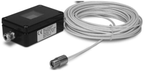
The pyrometers IN 510-N and IN 510 are digital remote-sensing thermometers with miniature sensor heads for non-contact temperature measurement. The versions IN 510 are equipped with an illuminated LC display which shows the actual temperature reading. All available parameters can be set via a built-in keyboard or via the corresponding software. The pyrometer has an analog output (0 - 5 V) that is proportional to the measured temperature and can be connected to the corresponding analog input of the controller.
Two types of optical heads are known with a 10:1 or 2:1 field of view. shows the spots at different measurement distances. For close focus for the 10:1 head, an additional lens can be used for small spot sizes that are a short distance away.
Figure 2. Impac pirometers optical heads and spot size.
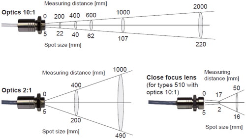
The experiments are performed by the handheld robot ODRO [Citation27,Citation28], equipped with a pyrometer optical head type with a field of view 10:1, with additional close focus lens. The main sensor head is positioned to measure the temperature in the area of the drill bit 10 mm from the point of contact with the bone. The purpose of this positioning is to avoid the influence of bone debris during drilling on the data for the measured temperature T1. Based on the main sensor data, the estimated value of the tip of the bit is calculated. One additional sensor head is positioned to measure the temperature of the drill tip after penetration through the first or/and second cortex – .
Figure 3. (A) Experimental setup with the ODRO robot and two sensor heads. (B) A closer look at the sensor heads.
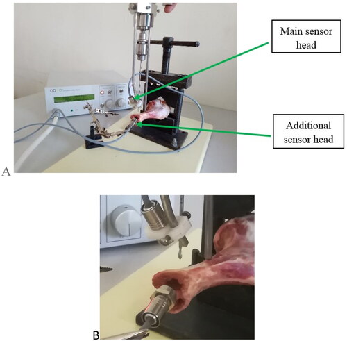
Unicortical and bicortical drilling, due to the higher density of cortical bone, is the riskiest manipulation in terms of increasing the temperature in the drilled area and the potential likelihood of thermal osteonecrosis. The heat is accumulated together with the hole depth prolongation and obtains its maximal value when the drill bit exits the bone. For that reason, the positioning of an additional sensor head to measure the temperature of the drill bit tip is focused on the drill bit penetration zone when the breakthrough of the first or second cortex occurs.
The data from the additional sensor head is used only to compare the calculated and measured temperature values.
The received experimental data is recorded and visualized by the PC software InfraWin version 5.0.1.65 as well as PC software TMCL–IDE version 3.5.0.0 (Trinamic Motion Control Language - Integrated Development Environment) – specialized software for programming and working with TRINAMIC motion controllers.
Experimental conditions
When executing drilling in ‘Cortex I’ or ‘Cortex II’ mode [Citation27], the drill bit translational movement automatically stops after drilling of the first or second cortex. Maximal penetration of the drill bit is within up to 1 mm after the breakthrough. Only the chisel edge outside of second cortex can be seen. The experiments were performed in the ‘Desired Depth’ mode. In this mode, the penetration of the drill is not automatically terminated after piercing the first (respectively the second) cortex, but after making contact with the bone, it continues until the set depth (‘Desired Depth’) is reached, regardless of whether the drill is located in the bone or outside of it. The experiments were performed as ‘Desired Depth’ is set 3-4 mm greater than the real depth of the first cortex or of the entire bone. Significant penetration of the drill bit through the wall of the first or second cortex can be achieved before stopping the drilling and respectively register (via an additional sensor head) the maximal temperature of the drill bit tip during the drilling operation.
The experiments were performed under the conditions presented in .
Table 2. Experimental conditions.
The measurements are carried out in a room with a temperature of 25 °C. The initial temperature of the drill bit and bone is not an important factor and during drilling it rises in both bone and screw from 25 °C to body temperature (37 °C). This does not change the properties of the bone and does not affect the maximum temperature increase [Citation29].
Results
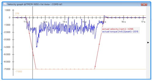
As noted above, to calculate the drill tip temperature value T2, it is necessary to measure the temperature T1 in real time from the additional temperature sensor in a certain area of the orthopedic drill outside the drilled bone, as well as to calculate l (length) and based on the information available in the ODRO management system.The feed rate controller [Citation28], as well as a force sensor inside the ODRO, captures required sets of data (force sensor data, position value, feed rate value). The current through the motor during drilling is about 1500 mA (1.5 A), as shown in , which, considering the torque constant and the gearhead, means a torque of about 0.58 Nm. In , the actual motor speed is 7000 RPM, which, after a 14:1 gearhead, means a drill speed of 500 RPM. The negative values of the current and the speed correspond to the desired direction of rotation of the bit - CW (clockwise direction). The motor starts when contact is made and stops after reaching the desired depth of the hole in the bone.
Figure 4. The actual current (blue line) and actual speed (red line) during unicortical drilling.
The deviation of data in time during unicortical drilling in ‘Desired Depth’ (10 mm) mode is graphically presented in . Time is expressed in arbitrary units (AU) of measurement; 1 unit is defined as the scoring time, i.e. the interval of time between two measurements. The maximum feed rate during drilling is 4 mm/s, drill speed is 500 RPM, and 20 times used drill bit.
Figure 5. Thrust force [N] (grey line), actual position [mm] (blue line), feed rate [mm/s x 10] (orange line) during unicortical drilling as function of time.
![Figure 5. Thrust force [N] (grey line), actual position [mm] (blue line), feed rate [mm/s x 10] (orange line) during unicortical drilling as function of time.](/cms/asset/4214b90a-b2f6-4c28-9e8d-ce1e95c45dc0/tbeq_a_2382185_f0005_c.jpg)
As can be seen from the figure, during the manipulation the feed rate changes [Citation28] depending on the execution phase as follows:
from 1 to 51 AU - contact search - 6 mm/s;
from 51 to 151 AU - realization of ‘center’ within 1 mm depth - 0.5 mm/s. This is especially important when making contact with the second cortex during bicortical drilling to avoid slipping of the drill inside the medullary canal;
from 151 to 261 – drilling – Vmax = 4mm/s.
The graph clearly shows the penetration of the drill bit through the first cortex (about 190 AU), where the value of thrust force sharply decreases from about 65 N to 40 N. Considering the values of feed rate and the time for performing the drilling (1 AU = 20 ms), the thickness of the cortex was on the order of 5 mm, and the cortical puncture was performed for 3 s. Penetration then continues at a speed of Vmax = 4 mm/s outside the bone until the set depth is reached.
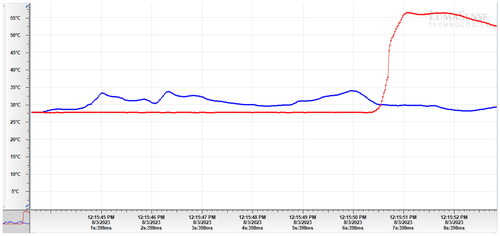
In are presented the graphs of the measured temperatures T1 and T2* during unicortical bone drilling. The temperature T1 was measured during the entire drilling process at a distance of 10 mm from the point of contact of the drill bit with the bone. One additional sensor head is positioned to measure the temperature of the drill tip after penetration through the first cortex – . The data from the additional sensor head is used to compare the calculated and measured temperature values.
Figure 6. Т1 (Blue line), T2* (red line) during unicortical drilling as function of time.
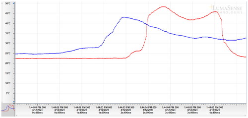
After making contact with the bone and starting drilling, the temperature T1 starts to rise. The temperature T2* remains constant because the additional sensor head is positioned to measure the temperature in the area in the medullary canal after the end of the first cortex (). After reaching a certain peak, as the depth of the realized hole increases, the temperature T1 begins to gradually decrease, and after the penetration of the drill bit through the cortex, this effect increases. After making contact, the bone drilling continues, the drill starts its penetration through the wall of the cortex and the temperature T2* rises sharply. Penetration then continues at a speed of Vmax = 4 mm/s outside the bone until the set depth is reached.
The sharp increase in the measured temperature (temperature peak) T2* corresponds to the measured temperature at the tip of the drill immediately after penetration and through the first cortex of the bone.
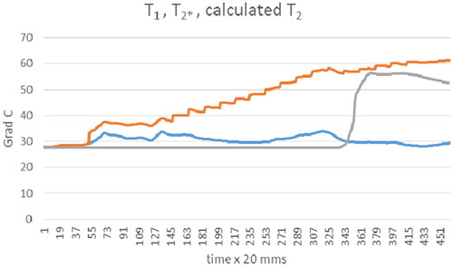
shows the graphs of the measured temperatures T1 and T2* as well as the calculated temperature T2. The calculated temperature T2 in accordance with EquationEquation (7)(7)
(7) is represented by the orange line.
Figure 7. Т1 (Blue line), T2* (grey line), calculated T2 (orange line) during unicortical drilling as function of time.
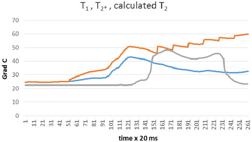
From it can be seen that the calculated temperature during the entire drilling time T2 exceeds 50 °C only from 121 UA to 132 AU, i.e. for a time of the order of 220 ms, after which the drill penetrates through the first cortex - the sharp increase in the measured temperature T2*. Immediately after the penetration of the drill through the bone wall, the measured temperature T2* (grey line), and calculated temperature T2 (orange line) are approximately equal. After that, the penetration continues with a speed of Vmax = 4 mm/s outside the bone until the set depth is reached, at which the drill bit tip, where the temperature during drilling reaches its maximum value, goes outside the measurement area of the additional sensor head, respectively the values of the measured temperature T2* begin to decrease and the difference between the measured temperature T2* and calculated temperature T2 continuously increases.
It should be emphasized that during real unicortical and bicortical drilling with the ODRO robot, after the penetration of the drill bit through the first, respectively second cortex, drilling is automatically terminated, after which the drill bit is withdrawn to the starting position. At the moment of penetration, the temperature of the drill tip reaches its maximum value during the bone drilling process.
From the results presented, it can be seen that at the moment of penetration the measured temperature T2* (gray line) and the calculated temperature T2 (orange line) are approximately equal. It can be concluded that during the real process, the calculated temperature (according to EquationEquation 7(7)
(7) ) has values that are close enough to the real temperature to which the drill tip is heated during bone drilling.
The results presented below in were obtained under the same experimental conditions as those in . The aim is to assess the repeatability of results obtained under identical conditions.
Figure 8. Thrust force [N] (grey line), actual position [mm] (blue line), feed rate [mm/s x 10] (orange line) during unicortical drilling as function of time.
![Figure 8. Thrust force [N] (grey line), actual position [mm] (blue line), feed rate [mm/s x 10] (orange line) during unicortical drilling as function of time.](/cms/asset/85189ad9-0b64-4830-af2b-56b624445aaa/tbeq_a_2382185_f0008_c.jpg)
Figure 9. Т1 (Blue line), T2* (red line) during unicortical drilling as function of time.
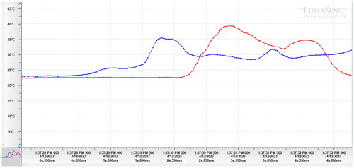
Figure 10. Т1 (Blue line), T2* (grey line), calculated T2 (orange line) during unicortical drilling as function of time.
The deviation of data in time during unicortical drilling in ‘Desired Depth’ (10 mm) mode is graphically presented in .
In , as well as in , there are presented the graphs of the measured temperatures T1 and T2* during unicortical bone drilling.
shows the graphs of the measured temperatures T1 and T2* as well as the calculated temperature T2. The calculated temperature T2 is represented by the orange line.
The experimental results presented in can be commented on in an analogous way, as well as those of , since they were obtained under the same conditions. The purpose of such a setup of the experiments was to check the repeatability of the obtained results. As can be seen from the results presented in and , the repeatability is quite convincing. See also supplemental Figures S1–S4.
The deviation of data in time during bicortical drilling in ‘Desired Depth’ (25 mm) mode is graphically presented in .
Figure 11. Thrust force [N] (grey line), actual position [mm] (blue line), feed rate [mm/s x 10] (orange line) during bicortical drilling as function of time.
![Figure 11. Thrust force [N] (grey line), actual position [mm] (blue line), feed rate [mm/s x 10] (orange line) during bicortical drilling as function of time.](/cms/asset/d615cd05-0133-4c76-bb48-da2e5b516425/tbeq_a_2382185_f0011_c.jpg)
The results of can be commented on in a manner similar to that of , given that they refer to bicortical rather than unicortical drilling. It should also be noted that bicortical drilling is performed in ‘Desired Depth’ mode and not in ‘Cortex II’ mode. In ‘Cortex II’ mode, after drilling the first cortex, the penetration is automatically terminated, then the search for contact with the second cortex (feed rate 6 mm/s), the realization of the center (feed rate 0.5 mm/s), and drilling (feed rate Vmax = 4 mm/s) until the penetration through the second cortex is recorded. Since the drilling is performed in ‘Desired Depth’ mode, after the first cortex is drilled (about 170 AU), the penetration continues (feed rate Vmax = 4 mm/s) until the set depth is reached. Penetration through the second cortex occurs around 379 AU, where the thrust force value drops sharply from about 55 N to 35 N.
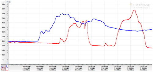
The graphs of the measured temperatures T1 and T2* during bicortical bone drilling are presented in . The sharp rise in the measured temperature (temperature peak) T2* corresponds to the measured temperature at the tip of the drill immediately after penetration and through the second cortex of the bone.
Figure 12. Т1 (Blue line), T2* (red line) during bicortical drilling as function of time.
The graphs of the measured temperatures T1 and T2* as well as the calculated temperature T2 are shown in . The calculated temperature T2 in accordance with EquationEquation (7)(7)
(7) is represented by the orange line.
Figure 13. Т1 (Blue line), T2* (grey line), calculated T2 (orange line) during bicortical drilling as function of time.
From it can be seen the calculated temperature during the entire drilling time T2 exceeds 50° C from 253 UA to 373 AU (where the drill penetrates through the second cortex), i.e. for a time of the order of 2.4 s.
The additional sensor head is positioned in the area where the penetration of the drill through the second cortex is expected. During the drilling up to the moment of penetration at 373 AU the additional sensor head measures only the ambient temperature, therefore there is a significant difference between the measured temperature T2* and the calculated temperature T2 up to the moment of penetration. The sharp rise in the measured temperature T2* corresponds to the measured temperature at the tip of the drill immediately after penetration through the second cortex of the bone. Also, the largest increase in the calculated temperature T2 corresponds to the drilling of the second cortex, where the drill penetrates through the second cortex, and at this exact moment a sufficiently good correspondence between the values of the measured temperature T2* and the calculated temperature T2 is observed.
The deviation of data in time during bicortical drilling in ‘Desired Depth’ (30 mm) mode is graphically presented in . Drilling is performed at maximal feed rate 2 mm/s, drill speed 1000 RPM, and 100 times used drill bit.
Figure 14. Thrust force [N] (blue line), actual position [mm] (orange line), feed rate [mm/s x 10] (grey line) during bicortical drilling as function of time.
![Figure 14. Thrust force [N] (blue line), actual position [mm] (orange line), feed rate [mm/s x 10] (grey line) during bicortical drilling as function of time.](/cms/asset/40b09dbe-372c-47ca-a896-44a23f2a255f/tbeq_a_2382185_f0014_c.jpg)
The results of can be commented in a manner similar to that of , considering that the value of feed rare Vmax is 2 mm/s, not 4 mm/s as it is for . In the graphs of the measured temperatures T1 and T2* are presented. The temperature T2* (red line) is measured after the penetration of the drill through the first cortex in the area of the bone canal (first peak), as well as after piercing the second cortex - the second peak of T2*.
Figure 15. Т1 (Blue line), T2* (red line) during bicortical drilling as function of time.
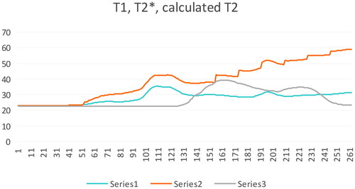
shows the graphs of the measured temperatures T1 and T2* as well as the calculated temperature T2. The calculated temperature T2 in accordance with EquationEquation (7)(7)
(7) is represented by the orange line.
Figure 16. Т1 (Blue line), T2* (grey line), calculated T2 (orange line) during bicortical drilling as function of time.
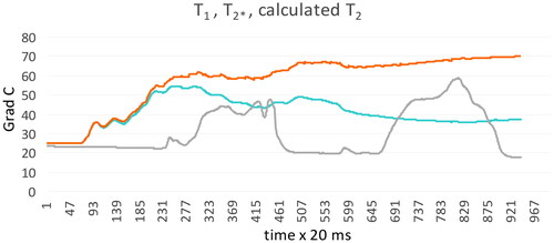
From it can be seen that the calculated temperature throughout the drilling time T2 exceeds 50 °C, with about after 507 AU (which corresponds to the penetration in the second cortex) remains close to 70 °C, then at 650 AU the bit penetrates the second cortex. The death of bone cells due to heat occurs instantly at 70 °C [Citation2,Citation30,Citation31]. It should be taken into account that the difference between the temperature of the bone and the temperature of the drill during drilling can reach up to 20 °C [Citation24]. However, the presented results clearly show the negative influence on the temperature increase during the drilling process of the reduced feed rate, increased drill speed, and the use of a reusable drill bit. See also supplementary Figures S5–S10.
The presented results reflect four experiments – two for unicortical and two for bicortical bone drilling manipulation. Unicortical bone drilling experiments were performed under the same experimental conditions. The purpose of such a setup of the experiments was to check the repeatability of the obtained results. As can be seen from the results presented in , the repeatability is quite convincing.
Bicortical bone drilling is the most frequently performed manipulation for fixation of long bone fractures. Bicortical drilling, due to the higher density of cortical bone, is the riskiest manipulation in terms of increasing the temperature in the drilled area and the potential likelihood of thermal osteonecrosis. As the hole becomes deeper the heat is accumulated and reaches its maximal value when the drill bit exits the second cortex. Thus the additional sensor head is positioned to measure the temperature on the drill bit tip on the drill bit penetration zone through the second cortex (or through the first cortex for unicortical drilling). Since the temperature during drilling reaches its maximum value precisely in this zone, it is particularly important to compare the results of the measured and calculated temperature value exactly in this zone. From the results presented, it can be seen that there is a sufficiently good correspondence between the values of the measured temperature T2* and calculated temperature T2.
From the presented experimental results, it can be concluded that there is a satisfactory agreement between the measured temperature at the tip of the drill bit T2* and the calculated temperature T2. It is important to note that the measured temperature does not exceed the calculated one, which is essential in terms of manipulation safety.
The presented experimental results show that based on the temperature measured by the main sensor head outside the bone, an estimate of the temperature at the tip of the drill bit during drilling can be obtained. This approach can be successfully applied in real operating room conditions (in vivo), as it does not require any additional processing of the manipulation object.
Discussion
When conducting experimental research in vitro, the temperature during drilling is measured in two ways - using thermocouple and using thermal infrared (IR) camera. The thermocouples are pre-implanted in the bone at a certain distance and at a certain depth from the place where the drilling should actually take place. However, several experimental studies demonstrate that the invasive method using thermocouple is impractical in medical conditions and preferred the thermal infrared (IR) camera as a non-invasive method [Citation32]. But the thermal camera only measures the temperature on the surface of the object (bone) – there is no information about the temperature inside the bone in the drilling area.
Placing thermocouples in bone, in close proximity to the drilling surface, as a means of measuring temperature is not a satisfactory solution to the temperature measurement problem because of the insulating effect of the bone, and if temperatures above 45 °C are reached then the temperature of the cutting edge of the drill must be significantly higher with serious damage to the hole surface [Citation33]. The method proposed here to measure the temperature of the drill outside the bone and calculate based on this measurement the temperature of the tip of the drill shows more reliable results, which is also confirmed by the experiments.
It can be concluded that both methods of temperature measurement are practically inapplicable during real bone drilling performance in surgical room (in vivo). Therefore, the temperature feedback during bone drilling process can be realized in two ways: – the first is through a temperature sensor with a special design (inside the drill bit) [Citation33], i.e. it must be of a special design. However, the use of such a sensor imposes serious limitations from a practical point of view. If temperature feedback is implemented in such a way, the drilling manipulation can only be performed with the presence of such type of special/custom design drill bit. The second is by using a standard temperature sensor positioned in a suitable place so that it does not interfere the manipulation in real conditions.
The approach presented in the work makes it possible, through the use of such a standard temperature sensor, to estimate the temperature of the tip of the drill bit during real bone drilling process performance.
A large number of theoretical and experimental studies have shown that 98%∼99% of the energy consumed in drilling (work done by drilling forces) is converted to heat [Citation21]. As already noted, much amount of work, done by mechanical subsystem of the robot, is converted directly into heat in the ‘bone - drill bit’ area. Heat is generated mainly from the cutting process (shear deformations) and the friction between the rake face of the drill bit and the bone chips. Secondary heating effects are caused by friction between the chips, drill bit body, and the bone [Citation19].
When deriving the equations, the assumption was made that all mechanical work is converted into heat in this area. It should be noted that the energy balance of the process made in this way is simplified. For example, the expenditure of mechanical energy to overcome the friction of drill bit non-cutting surfaces in the drilled hole is not taken into account. Also neglected is the magnitude of the heat flow from the surface of the drill through the walls of the so far drilled hole to the bone, as well as the magnitude of the heat flow from the surface of the drill outside the bone to the atmosphere. However, this makes it possible to minimize the necessary real-time calculations to obtain the estimated value of .
It should also be noted that the value of calculated in this way is always not less than the real temperature of the drill bit tip
, i.e. the ratio always applies
. This is essential with regard to the safety of the bone drilling process in relation to overheating of the bone tissue when this process is controlled together with calculated in such a way value of
.
Heat in the bone-tool region simultaneously increases the temperature of the drill bit and the bone. The temperature that a given material can reach depends on its specific coefficients of heat capacity and thermal conductivity [Citation13]. For the drill, the specific heat capacity is up to 3 times lower than that of bone [Citation34]. Thus, the temperature of the drill bit rises much faster than that of the bone. The difference between bone and drill temperatures can reach up to 20 °C [Citation19,Citation24], and the maximum drilling temperature is at the upper cutting edge of the drill [Citation24].
Because the level that marks the beginning of thermal osteonecrosis is still not a clear question which is under discussion in the scientific reports [Citation2,Citation4,Citation30,Citation31,Citation35], this should be taken into account when determining the safe temperature threshold of drill tip heating (for example 50° C), at which the control of drilling conditions of the drilling process to avoid thermal osteonecrosis of bone tissue should start. This mostly concerns the management of drill speed, since the drill speed, compared to other input parameters, is the main factor responsible for heat generation (contributes 78.87% to temperature rise) [Citation36–38] during drilling. This safe threshold determination and control algorithm creation are the object of further investigation.
In the scientific publications related to automated/robotic bone drilling, there is no data so far about the successful implementation of temperature feedback and, accordingly, temperature real time control of bone drilling process. Known systems for automated/robotic bone drilling [Citation6–9] do not offer temperature control of bone drilling process. This is due to the problems related to the implementation of temperature feedback.
Conclusions
The precise control of the cutting conditions (drilling speed and feed rate) that determine the thrust force and temperature in the drilling area during drilling is the main factor to obtain an optimal outcome. This can be achieved by realizing force and temperature feedback during drilling only in the conditions of the robotic bone drilling process. Force feedback is realized through a force sensor integrated into the mechanical system of the robot. In this study, based on the obtained sensor data, a computational approach was developed to estimate the upper limit of the drill bit tip temperature in the drilling area. This allows realizing temperature feedback during real time control of bone drilling process using a standard temperature sensor. The presented experimental results show a satisfactory agreement between the measured temperature at the tip of the drill bit T2* and the calculated temperature T2. The measured temperature does not exceed the calculated one, which is essential in terms of manipulation safety, when the so calculated temperature is used for temperature feedback creation during drilling. The implementation of temperature feedback during bone drilling process enables the control of the input parameters of the process to avoid thermal osteonecrosis of the bone tissue.
Authors’ contributions
Conceptualization, Boiadjiev T., Boiadjiev G. and Delchev K.; methodology, Boiadjiev T. and Kastelov R.; software, Boiadjiev T.; validation, Boiadjiev T., Boiadjiev G., Delchev K. and Kastelov R.; investigation and experiments, Boiadjiev T. and Chavdarov I.; writing—original draft preparation, writing—review and editing, Boiadjiev T., Boiadjiev G. and Delchev K. All authors have read and agreed to the published version of the manuscript.
Additional_experimental_results.doc
Download MS Word (537 KB)Disclosure statement
The authors declare no conflicts of interest.
Additional information
Funding
References
- Jamil M, Rafique S, Khan AM, et al. Comprehensive analysis on orthopedic drilling: a state-of-the-art review. Proc Inst Mech Eng H. 2020;234(6):537–561. doi: 10.1177/0954411920911283.
- Timon C, Keady C. Thermal osteonecrosis caused by bone drilling in orthopedic surgery: a literature review. Cureus. 2019;11(7):e5226. doi: 10.7759/cureus.5226.
- Zhang Y, Xu L, Wang C, et al. Mechanical and thermal damage in cortical bone drilling in vivo. Proc Inst Mech Eng H. 2019;233(6):621–635. doi: 10.1177/0954411919840194.
- Akhbar MFA, Sulong AW. Surgical drill bit design and thermomechanical damage in bone drilling: a review. Ann Biomed Eng. 2021;49(1):29–56. doi: 10.1007/s10439-020-02600-2.
- Welcome BM, Gilmer BB, Lang SD, et al. Comparison of manual hand drill versus an electric dual-motor drill for bedside craniotomy. InterdiscipNeurosurg: adv Tech Case Manag. 2021;23:100928. doi: 10.1016/j.inat.2020.100928.
- SMARTdrill 6.0 Now Available for Orthopedic Surgery. 2023. Available from: https://www.prnewswire.com/news-releases/smartdrill-6-0-now-available-for-orthopedic-surgery-300809777.html
- IntelliSense Drill Technology. 2023. Available from: https://www.mcginleyorthopedicinnovations.com/
- Louredo M, Díaz I, Gil JJ. DRIBON: a mechatronic bone drilling tool. Mechatronics. 2012;22(8):1060–1066. doi: 10.1016/j.mechatronics.2012.09.001.
- Gil J, Díaz I, Accini F. Inferring material properties in robotic bone drilling processes. Acta Bioeng Biomech. 2019;21(3):109–118. doi: 10.5277/ABB-01386-2019-02.
- Yen P, Ho T. Shared control for a handheld orthopedic surgical robot. IEEE Robot Autom Lett. 2021;6(4):8394–8400. doi: 10.1109/LRA.2021.3108522.
- Shakouri E, Sadeghi MH, Maerefat M, et al. Experimental and analytical investigation of the thermal necrosis in high-speed drilling of bone. Proc Inst Mech Eng H. 2014;228(4):330–341. doi: 10.1177/0954411914524933.
- Boiadjiev T, Boiadjiev G, Stoimenov N, et al. Experimental temperature evaluation during a robotized bone drilling process. Biotechnol and Biotechnol Equip. 2023;37(1):117–125. doi: 10.1080/13102818.2022.2160276.
- Augustin G, Davila S, Mihoci K, et al. Thermal osteonecrosis and bone drilling parameters revisited. Arch Orthop Trauma Surg. 2008;128(1):71–77. doi: 10.1007/s00402-007-0427-3.
- Chen Y, Hsiao C, Ciou J, et al. Effects of implant drilling parameters for pilot and twist drills on temperature rise in bone analog and alveolar bones. Med Eng Phys. 2016;38(11):1314–1321. doi: 10.1016/j.medengphy.2016.08.009.
- Lughmani W, Bouazza-Marouf K, Ashcroft I. Drilling in cortical bone: a finite element model and experimental investigations. J Mech Behav Biomed Mater. 2015;42:32–42. doi: 10.1016/j.jmbbm.2014.10.017.
- Agarwal R, Singh R, Gupta V, et al. Influence of cutting force on temperature, microcracks and chipmorphology during rotary ultrasonic bone drilling: An in vitro study. J Braz Soc Mech Sci Eng. 2022;44(7):301–311. doi: 10.1007/s40430-022-03608-6.
- Schofield E, Reiss S, Rey A, et al. Tool parameters to minimize temperature changes in bone drilling. Injury. 2023;54(3):904–909. doi: 10.1016/j.injury.2023.01.018.
- Hou Y, Li C, Ma H, et al. An experimental research on bone drilling temperature in orthopaedic surgery. TOMSJ. 2015;9(1):178–188. doi: 10.2174/1874088X01509010178.
- Lee J, Rabin Y, Ozdoganlar O. A new thermal model for bone drilling with applications to orthopaedic surgery. Med Eng Phys. 2011;33(10):1234–1244. doi: 10.1016/j.medengphy.2011.05.014.
- Amewoui F, Le Coz G, Bonnet A-S, et al. Bone drilling: a thermal model for bone temperature prediction. Comput Methods Biomech Biomed Eng. 2019;22(sup1):S305–S307. doi: 10.1080/10255842.2020.1714922.
- Hu Y, Yan Z, Li X, et al. Prediction model of bone drilling temperature based on heat source method in surgical rehabilitations. Procedia CIRP. 2020;89:263–269. doi: 10.1016/j.procir.2020.05.150.
- Amewoui F, Le Coz G, Bonnet A-S, et al. An analytical modeling with experimental validation of bone temperature rise in drilling process. Med Eng Phys. 2020;84:151–160. doi: 10.1016/j.medengphy.2020.07.007.
- Koenig H, Blackwell W. Electromechanical system theory. New York: McGrow Hill Book Company INC; 1961.
- Hou Y, Li C, Ma H, et al. A theoretical analysis on bone drilling temperature field of superhard drill. TOMEJ. 2016;10(1):109–125. doi: 10.2174/1874155X01610010109.
- Loitsyansky LG, Lurie AI. Course of theoretical mechanics: Volume 1 and 2, Moscow: Nauka (in Russian). 1995.
- Ben-Zvi Y, Reznikov N, Shahar R, et al. 3D architecture of trabecular bone in the porcine mandible and femur: inter-trabecular angle distributions. Front Mater. 2017;4:29. doi: 10.3389/fmats.2017.00029.
- Boiadjiev T, Boiadjiev G, Delchev K, et al. Far cortex automatic detection aimed for partial or full bone drilling by a robot system in orthopaedic surgery. Biotechnol and Biotechnol Equip. 2016;31(1):200–205. doi: 10.1080/13102818.2016.1234947.
- Boiadjiev T, Boiadjiev G, Delchev K, et al. Feed rate control in robotic bone drilling process. Proc Inst Mech Eng H. 2021;235(3):273–280. doi: 10.1177/0954411920975890.
- Augustin G, Davila S, Udiljak T, et al. Determination of spatial distribution of increase in bone temperature during drilling by infrared thermography: preliminary report. Arch Orthop Trauma Surg. 2009;129(5):703–709. doi: 10.1007/s00402-008-0630-x.
- Shu L, Bai W, Shimada T, et al. Thermographic assessment of heat-induced cellular damage during orthopedic surgery. Med Eng Phys. 2020;83:100–105. doi: 10.1016/j.medengphy.2020.05.014.
- Pazarci O, Torun Y, Ozturk A, et al. Comparative study of different drills for bone drilling: a systematic approach. Malays Orthop J. 2020;14(2):83–89. doi: 10.5704/MOJ.2007.016.
- Islam M, Kamarrudin N, Daud R, et al. Temperature measurement methods in an experimental setup during bone drilling: A brief review on the comparison of thermocouple and infrared thermography. J Phys Conf Ser. 2021;2129(1):012096. doi: 10.1088/1742-6596/2129/1/012096.
- Hillery MT, Shuaib I. Temperature effects in the drilling of human and bovine bone. J Mater Process Technol. 1999;92-93:302–308. doi: 10.1016/S0924-0136(99)00155-7.
- Akhbar MFA, Yusoff AR. Drilling of bone: effect of drill bit geometries on thermal osteonecrosis risk regions. Proc Inst Mech Eng H. 2019;233(2):207–218. doi: 10.1177/0954411918819113.
- Feldmann A, Wandel J, Zysset P. Reducing temperature elevation of robotic bone drilling. Med Eng Phys. 2016;38(12):1495–1504. doi: 10.1016/j.medengphy.2016.10.001.
- Islam MA, Kamarrudin NS, Suhaimi MFF, et al. Parametric investigation on different bone densities to avoid thermal necrosis during bonedrilling process. J Phys: conf Ser. 2021;2051(1):012033. doi: 10.1088/1742-6596/2051/1/012033.
- Singh R, Pandey P, Mridha A. An in-vitro study of temperature rise during rotary ultrasonic bone drilling of human bone. Med Eng Phys. 2020;79:33–43. doi: 10.1016/j.medengphy.2020.03.002.
- Tahmasbi V, Ghoreishi M, Zolfaghari M. Sensitivity analysis of temperature and force in robotic bone drilling process using Sobol statistical method. Biotechnol and Biotechnol Equip. 2018;32(1):130–141. doi: 10.1080/13102818.2017.1403863.