
 ?Mathematical formulae have been encoded as MathML and are displayed in this HTML version using MathJax in order to improve their display. Uncheck the box to turn MathJax off. This feature requires Javascript. Click on a formula to zoom.
ABSTRACT
This paper is concerned with a novel problem of determining the maximum spanning capacity of an elastic catenary arch under its own weight against in-plane buckling. The arch supports may be fixed or pinned or rotationally restrained. The arch is assumed to have a uniform cross-section throughout its entire length and the arch length is assumed to be inextensible. Additionally, catenary arches with a crown hinge are considered. The specific shape of a family of catenary curves is specified by the height-to-span ratio (or the horizontal force) which is to be determined for maximum buckling capacity of the arch. The Hencky bar-chain model is adopted for the elastic buckling analysis as it avoids the need to formulate the governing equation for buckling and it is also a simple model to understand and for coding. From the maximum in-plane buckling load of the optimal arch solution, the maximum spanning capacity of the arch can then be derived. Presented herein are the maximum spanning capacities, optimal arc length to span ratios and maximum buckling loads of catenary arches with various support and crown conditions.
1. Introduction
Heavy structures can fail prematurely under their own weight in a failure mode called self-buckling. In 1881, Greenhill (Citation1881) investigated the elastic bifurcation buckling problem of a free-standing vertical heavy column (i.e. fixed base support while its top end is free). He discovered that the heavy column would buckle under its own weight if its height exceeds
where E is the Young’s modulus, I the second moment of area of the column cross-section, q = ρgA the selfweight per unit length, ρ density, g the gravitational acceleration and A the cross-sectional area of the column. Based on this equation, Greenhill estimated the maximum height of a pine tree and interestingly found that it cannot grow more 300 ft tall; which sets the maximum height of trees on earth if trees are assumed to be prismatic and the branches are neglected.
If the heavy column’s top end is also fixed from rotation and lateral translation, Wang (Citation1987) derived the maximum height of the column against self-buckling to be
which shows an increase of 1.37 times in the maximum height vis-à-vis the fixed-free column.
Analytical solutions for other end restraints may be obtained from the book by Wang et al. (Citation2005) and Frich-Fay (Citation1966).
The self-buckling problem of standing heavy plates was studied by Wang et al. (Citation2002) for various edge restraints. This buckling problem allows one to deduce the maximum height of the standing heavy plate under its body force q and it is given by
where is the flexural rigidity of the plate, E the Young’s modulus, h the uniform plate thickness, ν the Poisson ratio, and C depends on the plate aspect ratio (i.e. width to height ratio) and the edge restraints. For example, for a standing heavy plate with fixed base edge and the three sides free,
Note that the aforementioned C value approaches the value corresponding to the maximum height of the fixed-free column (see Equation (10)) as the aspect ratio increases to a very large number, say 1000. The value of C for other aspect ratios and edge restraints may be obtained from the paper by Wang et al. (Citation2002).
In this study, we shall determine the maximum spanning capacity of a catenary arch under its own weight against self-buckling. The spanning capacity can be obtained from solving for the catenary arch shape associated with the maximum elastic in-plane self-buckling capacity. The Hencky bar chain model (C. M. Wang et al. Citation2020) will be adopted for the in-plane buckling analysis because of its simplicity to formulate and code.
2. Problem definition
Consider a catenary arch of uniform cross-section with flexural rigidity EI and has a span length of L and carrying its own weight q. The arch supports rotationally restrained with stiffness K, or pinned (i.e. K = 0), or fixed (i.e. K = ∞) as shown in .
Figure 1. Catenary arch under its own weight and coordinates system.
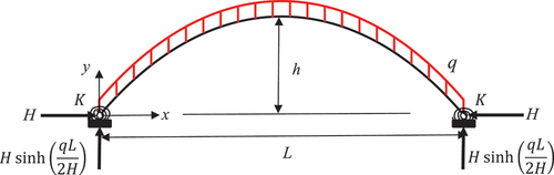
The catenary arch shape is given by
where the origin of the coordinate axes x, y is placed at the left-hand support of the arch as shown in , and H is the horizontal force in the arch. It is evident that the specific shape of the catenary arch is controlled by the horizontal force H in the arch. In view of EquationEquation (5)(5)
(5) , the height-to-span ratio
is related to the horizontal force.
The problem at hand is to determine the maximum spanning capacity (i.e. Lmax) of the catenary arch that will undergo in-plane self-buckling due to its weight. This problem is tantamount to determining the maximum in-plane self-buckling capacity of a catenary arch for a given span L and selfweight q by obtaining the optimal height-to-span ratio .
3. Hencky bar chain model for buckling analysis
In solving for the elastic bifurcation buckling load of a uniform column, Hencky (Citation1920) mooted a discrete structural model comprising rigid segments connected by frictionless hinges with elastic rotational springs having stiffness C = EI/a (where EI is the flexural rigidity of the column and a = L/n is the length of the rigid segments with L denoting the column length and n the number of segments). By using the principle of minimum potential energy, he derived a set of algebraic equations that form the governing eigenvalue equation. In this way, he bypassed the need to derive the governing differential equation for buckling of columns and solve the differential equation for the buckling load. Interestingly, Silverman (Citation1951) pointed out that Hencky’s algebraic equations are the same as those obtained from using the central first order finite difference method for buckling analysis of columns. Hencky discrete structural model has since been referred to as the Hencky bar chain model (HBM for brevity). As the number of segments increases, the HBM buckling load can be seen to converge to the exact buckling load of the continuum column from below, just like the finite difference model.
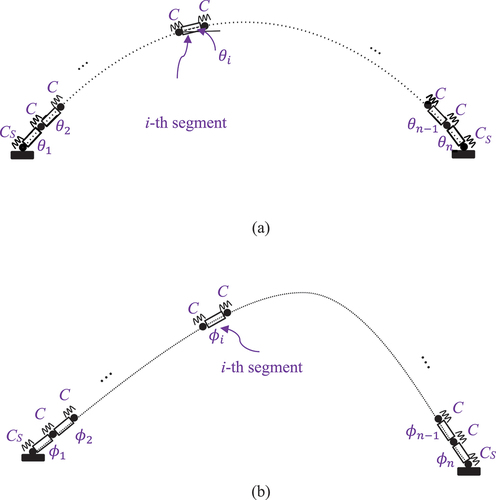
Wang et al. (Citation2020) has since developed the Hencky bar chain model (HBM) for buckling and vibration analyses of arches, frames and plates. Applying HBM for arch analysis, the continuum arch is discretised into n rigid arch segments joined by frictionless hinges with elastic rotational springs having stiffness C = EI/a where
and is the total arch length given by
shows the HBM for the catenary arch. For elastic rotationally restrained supports with stiffness, the HBM elastic rotational spring stiffness CS is given by (C. M. Wang et al. Citation2015)
Figure 2. HBM for buckling analysis of catenary arch (a) original undeformed state and (b) buckled state.
Note that for pinned supports and
for fixed supports.
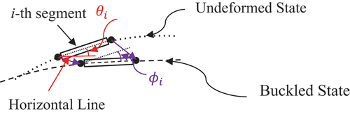
Let us denote the rotation vector of the rotational springs by
which is shown in .
Figure 3. Rotational angle ϕi of i-th segment in buckled state.
The elastic strain energy function U of the deformed rotational springs in HBM is given by
where the matrix is a n-order stiffness matrix for the elastic strain energy and it is given by
The potential energy of the selfweight in HBM is given by
where and the matrix
is a
stiffness matrix given by
where
In view of Eq. (11) and Eq. (13), the total potential energy of the HBM is given by
To ensure that the end supports do not move from their positions during buckling, the rotations must obey these two compatibility conditions (C. M. Wang et al. Citation2020)
and
where is the inclination of the arch segments with respect to the horizontal in the undeformed state, i.e.
where
In order to minimise the total potential energy Π subject to the satisfaction of the compatibility conditions Equations (18) and (19), LaGrange multipliers and
are employed. Therefore, the constrained problem can be transformed to an unconstrained one as follows:
To derive the stability criteria, we take the stationarity conditions of Eq. (18) with respect to the rotations and LaGrange multipliers
and
, that is,
where is given by
To avoid a nontrivial solution of the vector the critical buckling load of the catenary arch is obtained by setting the determinant of the governing stiffness matrix to zero, i.e.
The critical buckling load parameter, , is obtained by solving the characteristic Equation (21) for the lowest positive root.
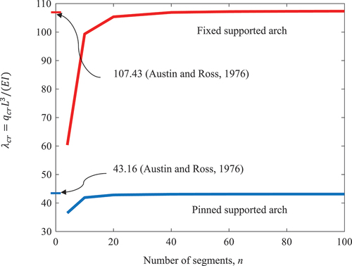
4. Convergence study and verification of HBM
A convergence study is first conducted to establish the number of arch segments n for accurate critical buckling load parameters . Consider a catenary arch with pinned supports and height-to-span ratio h/L = 0.3. The variation of the critical buckling load parameter
with respect to the number of arch segments n is shown in . It can be seen that the HBM results converge to the accurate solution from below as HBM makes the continuum arch more flexible. The buckling load parameter
for n = 80 is within 0.016% from
for n = 100 for the pinned supported catenary arch while parameter
for n = 80 is within 0.043% from
for n = 100 for the fixed supported arch. So one can take n = 80 to generate the buckling results herein. The buckling results are within 0.14% of Austin and Ross (Citation1976) results as shown in . This independent check verifies the HBM formulation and solutions.
Figure 4. Variation of critical buckling load parameters with respect to number of arch segments for a pinned supported and fixed supported arch with h/L = 0.3.
5. Maximum self-buckling load
The critical buckling load parameter of the catenary arch shape is dependent on the height-to-span ratio
. shows the variations of
with respect to
for elastic rotationally retrained supports with various
. It can be seen that the critical buckling load parameter
is sensitive to the variation of the height-to-span ratio
.
Figure 5. Variations of with respect to
for fixed supports, elastic rotationally retrained supports and pinned supports.
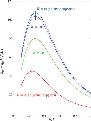
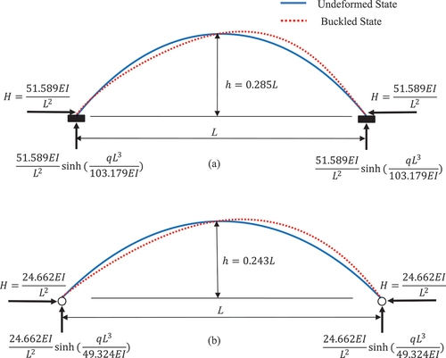
The optimal height-to-span ratio for maximum buckling load parameter may be obtained via the simple bisection method. The optimal shapes of the catenary arches for maximum self-buckling load and their buckled mode shapes are shown in . It can be seen that the height-to-span ratio of the optimal catenary arch gets smaller as the restraint at the supports are relaxed. For example, the height-to-span ratios are 0.285 and 0.243 for fixed arch and pinned arch, respectively.
Figure 6. Optimal shapes of catenary arches for maximum self-buckling load and their buckled mode shapes for (a) fixed supports, (b) pinned supports.
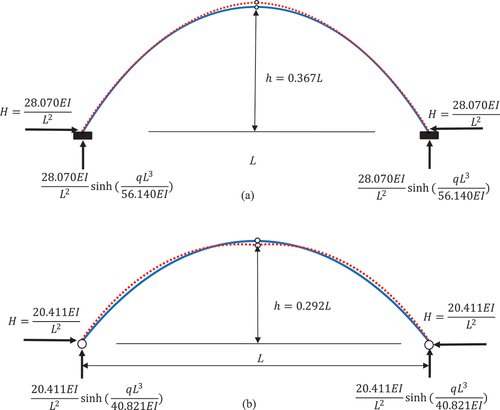
Additionally, we consider catenary arches with a structural hinge at the crown. These latter arch problems can be easily accommodated in the HBM model by setting the rotational spring stiffness at the crown of the arch to zero, that is, The variations of
with respect to
for various support conditions for the arch with the hinge at the crown are shown in . The optimal height-to-span ratios for catenary arches with a crown hinge are higher than their counterparts for arches without a crown hinge. shows the optimal shapes and buckled mode shapes of the catenary arches with a crown hinge for maximum self-buckling load. The buckling load curves for arches exhibit distinctive behaviours based on their support conditions and height-to-span ratio,
. Specifically, there are kinks in the buckling load curves at
and
for
and
respectively. The kinks represent the mode switching from a symmetrical buckling mode to an asymmetrical buckling mode.
Figure 7. Variations of with respect to
for elastic rotationally retrained supports with various
and crown hinge.
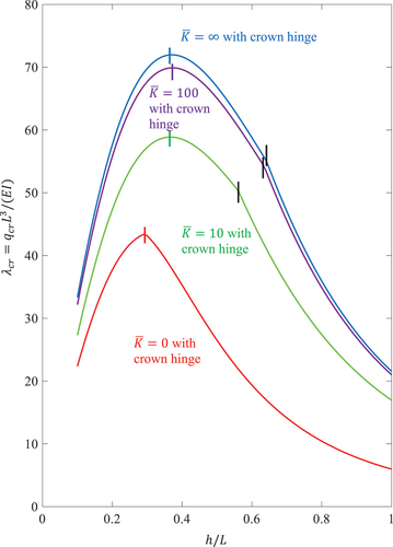
Figure 8. Optimal shapes of catenary arches with a crown hinge for maximum self-buckling load and their buckled mode shapes for (a) fixed supports, (b) pinned supports.
6. Maximum spanning capacity of catenary arches
Upon obtaining the maximum self-buckling load parameter one can readily determine the maximum spanning capacity of the catenary arch against self-buckling by
shows the maximum self-buckling load parameter for optimal height-to-span ratio
optimal arc length to span ratio
and maximum spanning capacity
for various arch support conditions and the arch crown condition.
Table 1. ,
for catenary arches with various support and crown conditions.
The maximum span capacity of arch for fixed supports is about 1.34 times larger than that of the arch with pinned supports. However, with a crown hinge, the maximum span capacity of arch with fixed supports reduces to about 1.18 times larger than its pinned supports counterpart. The maximum span capacity of arch is decreasing with the decreasing .
Additionally, shows that the optimal arc length to span ratio of fixed supported arch is greater than pinned supported arch by about 4%. With a crown hinge, this difference increases to about 8%.
In a study on the optimal design of catenary cable for lowest maximum tension, Wang (Citation2015) discovered that the optimum cable length is 1.258 times the distance between the pinned supports or h/L = 0.338. When the catenary cable is inverted, we have a catenary arch. This shows that for maximum buckling capacity, the optimal catenary arc length to span ratio of 1.144 has a shorter arc length (or lower rise to span ratio h/L = 0.243) than that of the optimal catenary arch associated with the lowest maximum compression force.
7. Concluding remarks
Discovered herein are the maximum spanning capacities and optimal arc length to span ratio of catenary arches against self-buckling for various support conditions and crown condition (see ). This information is useful to engineers to understand the limiting arch span for bridging a chasm or to cover a horizontal distance. Further extension of the spanning capacity may be achieved by using catenary arches with non-uniform cross-section.
Disclosure statement
No potential conflict of interest was reported by the author(s).
References
- Austin, W. J., and T. J. Ross. 1976. “Elastic Buckling of Arches Under Symmetrical Loading.” Journal of the Structural Division 102 (5): 1085–1095. https://doi.org/10.1061/JSDEAG.0004331.
- Frich-Fay, R. 1966. “On the Stability of a Strut Under Uniformly Distributed Axial Forces.” International Journal of Solids and Structures 2 (3): 361–369. https://doi.org/10.1016/0020-7683(66)90026-6.
- Greenhill, A. G. 1881. “Determination of the Greatest Height Consistent with Stability That a Vertical Pole or Mast Can Be Made, and the Greatest Height to Which a Tree of Given Proportions Can Grow.” Proceedings of the Cambridge Philosophical Society 4:65–73.
- Hencky, H. 1920. “Uber die angenaherte Losung von Stabilitatspoblemen im Raum mittels der elastichen Gelenkkette.” Der Eisenbau 11:437–452.
- Silverman, I. K. 1951. “Discussion on the Paper of Salvadori, M.G. Numerical Computation of Buckling Loads by the Finite Differences.” Transactions of the American Society of Civil Engineers 116 (1): 625–626. https://doi.org/10.1061/TACEAT.0006570.
- Wang, C. Y. 1987. “Buckling and Postbuckling of Heavy Columns.” Journal of Engineering Mechanics 113 (8): 1229–1233. https://doi.org/10.1061/(ASCE)0733-9399(1987)113:8(1229).
- Wang, C. Y. 2015. “The Optimum Spanning Catenary Cable.” European Journal of Physics 36 (2): 028001. https://doi.org/10.1088/0143-0807/36/2/028001.
- Wang, C. M., C. Y. Wang, and J. N. Reddy. 2005. Exact Solutions for Buckling of Structural Members. Boca Raton: CRC Press.
- Wang, C. M., Y. Xiang, and C. Y. Wang. 2002. “Elastic Buckling of Standing Vertical Plates Under Body Forces.” International Journal of Structural Stability and Dynamics 2 (2): 151–161. https://doi.org/10.1142/S0219455402000531.
- Wang, C. M., H. Zhang, N. Challamel, and W. H. Pan. 2020. Hencky Bar-Chain/net for Structural Analysis. Singapore: World Scientific.
- Wang, C. M., H. Zhang, R. P. Gao, W. H. Duan, and N. Challamel. 2015. “Hencky Bar-Chain Model for Buckling and Vibration of Beams with Elastic End Restraints.” International Journal of Structural Stability and Dynamics 15 (7): 1540007. https://doi.org/10.1142/S0219455415400076.