
ABSTRACT
Not counting domestic dwellings, it has been estimated that some tens of thousands of older masonry buildings and structures exist nationally and that many of these are potentially at risk of partial (or worse) collapse from falling or dislodged masonry. This has significant implications for building owners, managers, insurers, the local and national economies, and the urban environment. The problem is caused mainly by the slow deterioration of masonry under atmospheric and other environments and by the corrosion of so-called wall-ties, relatively thin pieces of steel that tie the outer leaf of masonry walls to the inner leaf. The problem is likely to be particularly severe for scenarios such as synoptic windstorms and earthquake events as this causes area-wide damage, and potential wide-spread loss of human life – losses that could be prevented by timely intervention. The present paper deals with the research framework and the methodology being employed in a long-term project to develop tools for cost-effective structural masonry assessment and for risk estimation under structural deterioration conditions. Some early findings with potential immediate practical implications are given. Because the effects of deterioration are long-term, the overall project outcomes will take some years to come to fruition. They will be reported in due course.
1. Introduction
Masonry construction in Australia has a long history (Page Citation2019; Edwards and Whener Citation2019) and continues to play a major part in Australian urban and suburban infrastructure, not only in major structures but also in domestic construction, consistent with modern requirements for wind and earthquake resilience [AS1170 (Citation2021); AS3700 (Citation2018)]. Modern external masonry walls typically rely on steel connectors (or fitments) that secure them back to load-bearing concrete, steel, timber, or masonry structure (). These fitments are often called ‘wall-ties’ (). They transfer wind and earthquake forces to the load-bearing structural system. For medium and high-rise construction metal fitments also include ‘shelf-angles’ that are used to support the masonry’s higher stories.
Figure 1. Schematic of fitments in masonry.
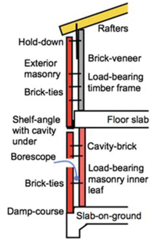
Figure 2. Loss of wall-tie connection, corrosion and mortar degradation.
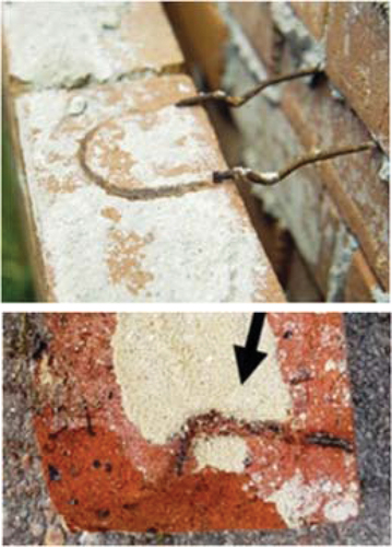
Traditionally, and still in addition to modern plastic or coated metal fitment practice, fitments such as wall ties and shelf angles are almost always of steel construction, typically galvanised mild steel, but stainless steel is also used. A serious problem for long-term durability and building safety is that fitments are prone to deterioration – principally corrosion (Chaves et al. Citation2021, Citation2022). Much previous experience has shown that, in most cases, the deterioration is hidden from view () and that the seriousness of the damage that was eventually revealed could not have been predicted. It may occur without apparent warning. An example is the recent collapse of the outer leaf of a cavity masonry wall of a nightclub in Perth (WAToday Citation2019) as well as others (). Sudden collapse of deteriorated masonry wall fitments is not limited to the Australian context. For example, in 2015, a section of a 64-year-old south-facing 5-storey clay brick wall failed due to vibrations from nearby rail tracks (Hollinshed and O’Niel Citation2015). Although not always well reported, such cases are of particular concern to emergency services, regulators, those with infrastructure and response responsibilities and building owners and insurance companies. The central importance of the stability fitments, particularly wall-ties () is well-established (Standards Australia AS 3826 Citation1998; Standards Australia AS 3700 Citation2018; Jardim Do Nascimento et al. Citation2019; Masia Citation2020), including quantitatively (Chaves et al. Citation2021) and qualitatively from observations of the structural damage resulting from high load events such as earthquakes (Page Citation2019; Masia Citation2020).
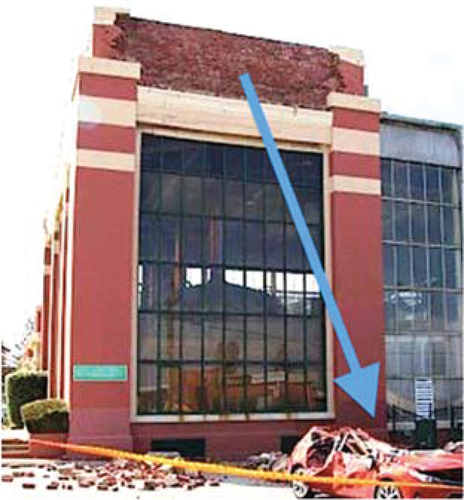
Figure 3. Collapse of parapet, 1930s Matilda Bay Brewing complex in 2017 (Mayes Citation2017).
Unfortunately, little information is available about the environmental conditions within wall cavities as a function of time. Further, conventional visual inspection techniques cannot reveal or identify structural deficiencies caused by longer-term deterioration within the mortar joint of the external leaf (). More advanced methods for inspection and prediction are required. With an extensive history of rebuilding or retrofitting war-damaged infrastructure, various new retrofitting materials are being examined in Europe to extend service life of key historical apartment and tourist infrastructure, however the issue of knowing which walls are vulnerable remains (European Commission Citation2023). The problem is particularly acute in coastal areas where clay or concrete masonry multi-storey developments are commonplace in high-rise apartment and for office buildings. Masonry is highly durable, but the fitments () are prone to deterioration. This is also the case away from the coast () (Maqsood et al. Citation2016; Mayes Citation2017; Chaves et al. Citation2021). A recent report (Wehner et al. Citation2020) concluded that the collapse of older buildings such as in represented a significant risk for all built environments in Australia. It also noted that the overall risk was increasing, owing to the ageing of structures, the continued desirability of masonry construction and continued population growth. Importantly, the report noted the need to extend the service life of existing schools, hospitals, and other critical structures.
Discussions with regulators and industry over recent years (Wehner et al. Citation2020; Chaves et al. Citation2021) have made clear that at present for masonry structures there are no robust procedures for assessing the structural integrity and the expected rate of deterioration. In particular, there are tens of thousands of buildings nationwide, including residential and commercial structures for which masonry can dislodge and perhaps collapse, mostly without apparent warning. This has implications Australia-wide, including for urban, rural, and regional infrastructure. The present paper reports on the methodology and techniques being developed for a long-term (multi-year) project focusing on predicting the resilience of masonry building stock under time- and local climate-dependent deterioration conditions. It also reports some aspects of the early findings, noting that because structural deterioration is a slow process, the main project outcomes will take several years to develop. They will be reported in due course. The present paper deals mainly with the project methodology and techniques. As noted, the project outcomes are intended to be used by Government and other agencies or parties as a basis for risk assessment of masonry construction, including recognising the gradual improvement over time of (a) quality of construction and (b) wall-tie structural capacity and corrosion resistance.
2. Methodology
This section outlines the methodology being applied to the project and aspects being investigated, including the integration of physical modelling and deterioration (Terry et al. Citation2023) and aspects of non-destructive investigations (Lam, Masia, and Chaves Citation2023). A summary of these follows.
2.1. Field inspections and in-situ condition assessments
As part of the project programme, a number of actual buildings will be examined. Although early in the project, as this stage building inspections have commenced. This is being done in conjunction with building owners and managers. The inspections are planned to continue for at least two years and will, at minimum, examine buildings of different ages, heights, and proximity to the ocean. They will be examined, for each building elevation and at different floor levels, for the condition of wall-ties within the masonry cavity and in the mortar bedding (), particularly for the external masonry leaf. A commercial borescope (e.g. Olympus Series C 2 m Videoscope) available through the Industry Partners will be used for wall cavity inspection. The intent is that at least one brick per elevation will be removed to permit taking of mortar and wall tie samples for visual assessment and for material composition analysis.
The methodology calls for, wherever possible, inspections to be made shortly after extended periods of wetness (typically autumn, or spring). This is to attempt to capture the highest Relative Humidity (RH) in the wall cavities (). Both cavity and external RHs and temperatures will be measured with portable detectors. Similar cost-effective environmental sensors, air pollution (sulphates) and salt deposition detectors with in-built-data storage for these measurements, with a data download facility also will be applied, in each case with long-term continuous data collection. The intent is that these measurements and data will provide baseline information for the comparative studies of the corrosion of masonry fitments. This work will also provide for comparisons to standardised indices of local atmospheric corrosivity as widely used in industry [AS4312 (Citation2019)].
2.2. Experimental testing to establish corrosion science of wall-ties
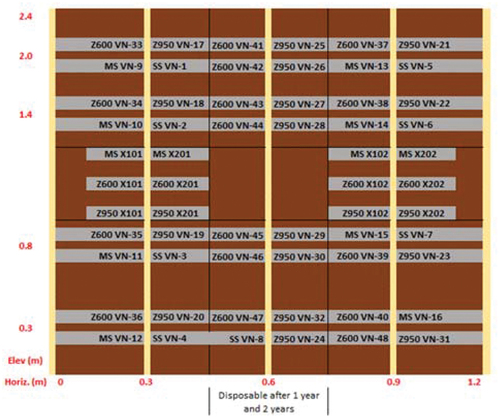
Two purpose-built experimental housing modules have been constructed near the Pacific Ocean at Belmont (NSW) (). They comprise brick veneer and cavity brick construction with standard masonry construction practice employed through the use of a professional third-party bricklayer and carpenters. They are each 1.8 m × 1.8 m in exterior plan dimension and have a wall height of 2.4 m, with a steel (Colorbond) pitched roof (). They have a door for internal access to permit monitoring of the interior climate as well as make observations of the interior wall condition and to allow samples to be taken. They also allow detailed monitoring of cavity wall conditions. Provisions have been made via various internal removable brick access points (Brick cavity) and removable internal lining panels (Brick veneer) to permit periodic visual condition assessment of the wall-ties for the duration of the project (Terry et al. Citation2023). Relative humidity, temperature, and dew point sensors have been placed within each unit cavity accessible through access points, as well as internally and externally to each house unit. These types of data are needed to complement qualitative observations of deterioration since corrosion is known to depend on several factors, including material composition, temperature, time of wetness, pH of mortar and potential galvanic interactions (Chaves et al. Citation2021). The present study will account, as accurately as experimentally possible, for these influences. The conditions surrounding, inside, and outside the experimental masonry wall cavity are being monitored on a continuous basis. The experimental programme includes the installation and testing of wall ties for all exposure classifications (i.e. light and heavy galvanised, stainless steel and control plain steel) (Standards Australia AS 3700 Citation2018). Tie locations within a cavity and the wall orientation relative to prevailing weather conditions are also part of the experimental programme (). This includes monitoring of corrosion effects (Terry et al. Citation2023).
Figure 4. Instrumented house modules for detailed wall-tie corrosion assessment, with access door located on west elevation (top) and plan view with cardinal orientation (bottom)(Terry et al. Citation2023).
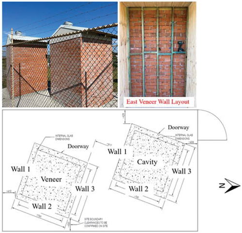
Figure 5. Example layout plan of commercially available brick veneer wall ties. MS denotes plain steel ties, SS denotes stainless steel ties, and Z600 and Z950 represent light and heavy galvanised, respectively (Terry et al. Citation2023).
2.3. Non-destructive structural assessment of masonry wall panels
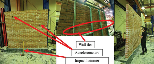
For the structural assessment of masonry walls with aspects of deterioration, the experimental programme will use modal testing of wall response. This is being done using brick wall panels 2.4 m by 2.4 m in elevation (). The programme includes one full-scale structural timber brick veneer wall and one full-scale double-leaf cavity brick wall. Wall panel structural performance is being applied through modal analysis since modal parameters such as natural frequencies, mode shapes and damping ratios are good damage indicators. They are directly related to the changes in stiffness and mass of the structure. Mode shape is the deflection pattern corresponding to a particular natural frequency and represents the relative displacement of all parts of a structure (Das, Saha, and Patro Citation2016; Avitabile Citation2017). This allows damage to the structure to be detected since such damage also causes a change in the dynamic deflection pattern. In the project experimental programme, the only source of damage will be that resulting from the slow deterioration of the conditions of wall ties. Modal analysis will assist in identification and in the location of deteriorated wall ties within veneer and cavity walls, based on the changes in modal responses. The results obtained can then be calibrated against empirical field data to differentiate between damage caused by wall tie deterioration and other commonly expected defects (e.g. mortar cracks, construction errors and nonconformity with building standards).
Figure 6. Brick veneer wall system in the University of Newcastle Civil Eng. laboratory for non-destructive assessment (scale 1:1). Input modal impact hammer shown on right, with removable wall ties shown in the middle, and adjustable output accelerometers shown on left.
The wall specimens were constructed to best practice modern building practices (Standards Australia AS 3700 Citation2018), by a professional third-party brick layer. Provision has been made for cavity and wall tie access. Each individual tie, or complete rows, can be readily disconnected through testing regimes to account for various permutations of localised corrosion section loss and the extent of stability loss. It is noted that simply detaching wall ties could compromise the realism of stability loss, so further tension and compression tests of individual timber nailed wall ties embedded in brick couplet specimens will be carried out (Terry et al. Citation2023).
For the testing procedure, a 4 × 4 equally spaced impact grid across the 2.4 m by 2.4 m wall panel specimens is being used. The excitation impact location aligns with the location of wall tie rows. Measurements are taken with at least two accelerometer reference locations defined at the grid points. The number and location of the grid points may be subject to change as the project progresses. Grid point locations also depend on the data processing capability of the data acquisition systems and the aliasing effect of the excited mode shape measurements. Ideal excitation locations and measurements have been determined by the driving-search-point method (Lam, Masia, and Chaves Citation2023) to ensure the highest quality of results. The impact hammer method has been selected as one of the excitation mechanisms to vibrate the wall due to its relative simplicity and convenience. Optical and laser-based methods also will also be used, and their results will be compared directly to those from the hammer method. Computer controlled vibration inducing shakers will also be used. In addition to the accelerometer sensors, optical and laser-based methods will also be used to measure vibration. A Scanning Laser Doppler Vibrometer (SLDV) will be used for its capability in data acquisition with refined vibrating velocity measurements, without the need to be in contact with the structure (Lam, Masia, and Chaves Citation2023). The associated costs, increased operation complexities and usefulness of these tools for extensive field application are important factors and are being investigated as well.
3. Preliminary observations
3.1. Wall-tie condition assessment from field inspections
To date, only a small number of actual buildings have begun to be inspected in the project, but information from earlier inspections is available. This permits some preliminary observations to be made. An example is the field investigation and in-situ condition assessment of a cavity brick residential apartment complex comprising one 10 storeys high and two 3 storeys high buildings, located in a metropolitan area 8 km from the Pacific Ocean. The buildings were inspected primarily for signs of cavity wall tie corrosion. According to relevant government departmental sources, the construction of the three buildings commenced in 1953. The complex opened for residents in 1956. Information about rectifications made since construction has not (yet) become available for the present project. However, some relevant information was obtained from site inspections conducted during more recent remediation works for reinforced concrete balcony slabs supported by external load-bearing masonry walls. Both internal and external brickwork consisted of solid-frogged units providing a typical overall wall thickness of 270 mm. This includes approx. 50 mm of cavity. All elevations of all three buildings have a generous amount of embedded ventilation bricks at both the top and bottom of walls, and at every few metres.
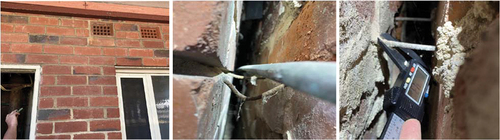
Because the facility was still in use, physical removal of brick units to permit cavity inspection was not feasible. However, the replacement of door and window timber frames allowed inspection of the overall condition of the wall ties within the wall cavities. This revealed U-shaped wire wall ties (Abey Citation2017) at every 1000 mm horizontally and 600 mm vertically. shows an example of an area so inspected and from which wall tie and mortar samples were taken for investigation. X-ray Diffraction (XRD) analysis suggested that the mortar was a lime-heavy based mix, consistent with standard practice at the time of construction. Although the wall ties overall appeared to be in good condition, some showed signs of rust. For the external walls, the east elevation ground floor of one of the 3-storey buildings showed the brickwork to be in good condition, but the mortar integrity was considered fair to poor. This likely would permit water percolation into the cavity, thereby increasing the humidity in the cavity. This correlates with the higher corrosion generally observed on the portion of the wall tie embedded in the outer leaf ().
Figure 7. Example 68-year-old wall east elevation inspected showing ventilation bricks and cavity access point (left), wall cavity ties showing brown steel corrosion staining as evidence of loss of protective galvanised layer (middle), and example of remaining thickness measurement (4.3mm), suggesting a likely original thickness of 5 mm (Ancon Citation2021) (right).
The site inspections showed that wall ties of well-ventilated wall cavities could remain in relatively good condition beyond the 50-year target design life. Overall, the inspections indicated that the location within a wall cavity could influence wall tie corrosion, that corrosion where it occurred was more severe adjacent to the external wall leaf and that poor construction practice(s) can influence wall tie durability over time. As expected, ties for masonry with east and west elevations appeared to be in better condition than those for south elevation walls, for which the wall ties showed more signs of corrosion. This aligns with the fact that south elevations normally are more shaded throughout the day, and thus retain higher relative humidity for longer periods of time compared to other elevations. Current efforts to obtain more in-situ information for other buildings and thus construct a more complete understanding of the problem through improved correlations are expected to allow conclusions to be drawn in the final report as to the most influential parameters on wall tie durability.
3.2. Corrosion monitoring of house module wall ties
The house modules specially constructed for this project were completed only in August 2023. Over the short exposure period to date, only insignificant thickness losses of wall ties have occurred, for all wall tie materials. The cavity environmental sensors are monitoring temperature and relative humidity across the spring and summer months. show illustrative example data sets for one week during the spring to summer transition. These will be complemented by data for the reminder of the total experimental programme and thus provide information likely to be useful for understanding how the micro-climate within the cavity differs from external conditions, and how that may affect the corrosion mechanisms for the various cavity locations.
Figure 8. Example logged cavity temperature data (°C) for the brick veneer house module comparing differences by elevation (left) and internal vs external conditions (right).
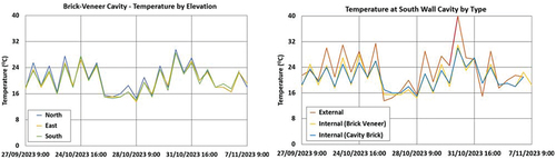
Figure 9. Example cavity logged relative humidity (%RH) data for brick veneer house module, comparing differences by elevation (left) and internal vs external conditions (right).
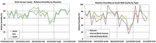
Examples of data for internal cavity temperatures between East, North and South elevations are shown in (left). Although preliminary, it suggests a slightly lower temperature (range) for the south elevation cavity, consistent with observations for the in-situ inspections. Reinforced by open meteorological public records (Bureau of Meteorology Citation2024), these records suggest that storms or periods of prolonged wetness do not influence the observations that the south elevation remains cooler, despite overall reduction of ambient temperature. (right) tends to support this observation by showing a fast increase in external temperature compared to internal masonry leaf temperatures for the south and north elevations. It also shows a noticeable delay in cavity temperature rise over the course of the week post wet period. Similar observations can be made in terms of relative humidity (RH) (). The relative humidity in the wall cavity on the south elevation is noticeably higher over the same period compared to those for the north, and even east elevations. Moreover, internal humidity levels remain higher compared to external levels. Prolonged lower cavity temperatures combined with higher relative humidity levels are likely to lead to prolonged condensation conditions and thus for increased corrosion to occur. These preliminary observations will be augmented by the results of further detailed inspections and will then allow correlation with mortar humidity levels.
3.3. Structural assessment of masonry wall panels
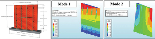
Computational modelling of the masonry veneer and cavity wall panels is the part of the project plan to improve understanding, in a cost-effective way, of the response of masonry wall panels under dynamic loading. As noted, the non-destructive modal response analysis of the masonry construction system considered in this project uses finite element modelling (DIANA 10.5) (Lam, Masia, and Chaves Citation2023). Preliminary numerical modelling has assisted in the selection of specimen configurations, excitation and measurement techniques, sensitivity of measuring equipment, locations of excitation and measurement points, etc. An example of two main modal shapes identified to date is shown in . Given that masonry is a composite material which consists of units and mortar, the properties of masonry are influenced not only by the material properties of unit and mortar but also by the joint arrangement, the anisotropy of units, joint widths, etc. (Lourenço and Rots Citation1997). A simplified micro-modelling strategy was adopted for this project to reduce computational effort while still providing a sufficient level of accuracy, as demonstrated by earlier research for representing possible failure mechanisms (Heffler et al. Citation2008; Li et al. Citation2019) including the standardised effects of joint tensile cracking, joint sliding, unit direct tensile cracking, unit diagonal tensile cracking and crushing failure (Standards Australia AS 3700 Citation2018).
Figure 10. Example brick veneer wall panel numerically simulated (left) structural vibration behaviour and predicted modal parameters (Bending and Torsional) and associated natural frequencies (16 Hz mode 1 and 24 Hz mode 2). The colours represent the extent and direction of movement (Scale bar in millimetres) (Lam, Masia, and Chaves Citation2023).
Non-destructive methods that currently are considered suitable for masonry structures include thermal imaging, acoustic, radar methods and modal analysis (Lam, Masia, and Chaves Citation2023). The first three are widely used for detecting cracks, voids, and moisture-related issues of masonry structures (Hussain and Akhtar Citation2017). However, similar to borescope inspections, the limitation is that these methods only provide indirect indications of deterioration of the wall ties. From a structural engineering point of view perhaps slightly more useful is modal analysis and testing since this can capture the global structural behaviours instead of focusing on a particular damage type. This approach can serve as a first indicator of potential damage issues through identifying ‘soft’ walls, that is, walls likely affected significantly by deteriorated wall ties, as based on their modal responses being below the expected threshold for well-supported and undamaged masonry wall structures.
Accelerometer and other vibration-based non-destructive testing methods are well-established but, on expert advice, were considered impractical and too costly for complex masonry structures of several storeys and for assessing multiple buildings, perhaps over wide geographic locations. They also may involve logistical challenges with gaining building access, etc. Whether the responses to the induced vibration can be measured to a sufficiently high degree of accuracy also needs to be considered. Discussions with industry practitioners indicate that this can be achieved, noting that for masonry the area of influence from an induced source of vibration is limited. To proactively overcome these expected challenges, the project team is developing a new non-destructive technique using optical and laser-based dynamic sensing. For optical sensing, a computer-vision-based target-free 3D vibration technique shall be developed for non-contact in- and out-of-plane displacement measurement of masonry walls (Kuddus et al. Citation2019). The laser-based measurement approach is a vibration monitoring technique based on Scanning Laser Doppler Vibrometry (SLDV). It measures the vibration signature of a structure subject to a source of dynamic excitation (Klun et al. Citation2019) using commercially available equipment. Whether the SLDV measurement technique is effective and sufficiently accurate for the expected low frequency excitation of high mass, highly damped masonry walls is also being investigated.
4. Discussion
The present project is aimed at using both field observations and their correlation with laboratory studies to allow the eventual research findings to be translated to practical guidance for industry, building also on recent relevant research (Muhit, Stewart, and Masia Citation2021; Hossain, Totoev, and Masia Citation2021; Muhit, Masia, and Stewart Citation2022). The previous works have shown that masonry veneer wall system behaviour, including collapse load, can be modelled numerically, to a high degree of accuracy, using inputs of selected load configurations and intensities and with quantitative models for the behaviour of wall-ties, masonry construction and, where relevant, any framing system (Terry et al. Citation2023). The present project builds on this work by the use of stochastic finite element modelling with inclusion of examination of the influence of spatial variability (Lam, Masia, and Chaves Citation2023). Such system variability arises from variabilities in strength and stiffness properties of the masonry itself, from the brick-ties and from the structural framing connection. This stochastic modelling approach for masonry construction is being extended to enable the prediction of the probability of structural system failure under hazards such as arising from significant wind or earthquake loading. It will be extended to deal with cavity brick walls and, importantly, will include deterioration mechanisms that will be formulated from the test data and the corrosion trends for brick ties as previously obtained (Jardim Do Nascimento et al. Citation2019) but now with data for material strength, including information from field observations for older masonry construction. The numerical work, based on finite element modelling and 3-dimensional simplified micro-modelling will be adopted from earlier research (Hossain, Totoev, and Masia Citation2021; Lam, Masia, and Chaves Citation2023). Available statistical information and probability distributions will be used (Muhit, Masia, and Stewart Citation2022; Terry et al. Citation2023) to enable the correct capturing of the non-linear, spatially variable, material behaviour in the wall ties and the masonry, including cracking and collapse, using the well-documented technique of fragility curves. Fragility curves, sometimes portrayed as risk matrixes, provide an effective and relatively simple way to graph the influence of certain parameters on the overall probability of failure (Edwards and Whener Citation2019; Muhit, Masia, and Stewart Citation2022).
As noted, the present project is an on-going structural engineering assessment project, aimed at assisting building owners, and managers and government agencies in making decisions or recommendations about building safety for masonry buildings. This requires the assessment of building condition as well as overall integrity management and the forecasting of potential impact of failures. As noted also, this is considered helpful for emergency service response preparations. The need for this was laid out in a broader context by the Royal Commission into National Natural Disaster Arrangements (Citation2020) that examined co-ordination, preparedness for, response to and recovery from natural disasters (including floods, bushfires, earthquakes, storms, cyclones, storm surges, tornadoes, landslides, and tsunami). That Commission observed that ‘the extent to which structures and communities are exposed and vulnerable to natural hazards should be identified and communicated, so people can make informed decisions about the risk with which they are willing to live, and the actions they can take to mitigate this risk. The present project is expected to contribute to these aims through enabling the provision of timely information about the condition and integrity of masonry buildings (Heintz and Rojahn Citation2020). In turn this will assist in the management of public risk. Evidently, the project has implications also for private industry. It is supported by government agencies such as WA’s Department of Energy, Mines, Industry Regulation and Safety (Citation2021) (that includes WorkSafe, Consumer Protection and Building and Energy, the building regulator).
5. Conclusion
Despite the existence of established cost-effective remediation solutions for unstable masonry wall systems, current inspection practices are not only onerous but, importantly, ineffective in detecting corrosion of metal wall stability fitments, particularly within the mortar joints of masonry walls. This situation is being addressed in the present project.
Wall cavity micro-environment corrosion conditions are sufficiently different from external atmospheres to warrant development of more accurate, empirically validated, models for the prediction of extreme, perhaps localised, corrosion losses.
The background work for the present project indicates that current non-destructive structural assessment techniques can be adapted and permit progressive assessment and prediction of wall stability. This will be done by identifying critical instability mode shapes, indicating areas of localised loss of stiffness within a given wall panel and thereby areas with elevated corrosion risk.
The present preliminary work has demonstrated the feasibility of integration of established techniques and new empirical findings into the desired comprehensive assessment and prediction framework. In turn this can be expected to provide Government and other agencies and organisations a basis for improved regulations for masonry construction and improved risk assessment, with implications also for the management of emergency services.
Author contributions
Conceptualisation, I.C., M.M., R.M., S.deP., J.V., and W.C.; methodology, I.C., M.M., R.M., L.T., C.L., J.V., A.H., and B.S.; validation, I.C., M.M.; investigation I.C., M.M., R.M., and S.deP.; resources, J.V., S.deP., and I.C.; writing: original draft preparation, I.C.; writing: review and editing, I.C., M.M, S.deP., R.M. and W.C.; visualisation, I.C., L.T., C.L., B.S., and S.deP.; project administration, I.C., and M.M.;
Acknowledgments
The authors would like to acknowledge the pivotal financial support from the Australian Research Council and the Western Australian Government Department of Energy, Mines, Building Regulation and Safety via Linkage Project LP220100028. The authors also would like to take this opportunity to appreciate all the in-kind contributions from the various industry partners who have formally committed their involvement for the duration of the project.
Disclosure statement
No potential conflict of interest was reported by the author(s).
Additional information
Funding
References
- Abey. 2017. The Abey Brickie’s Guide – Aussie Made for Aussie Trades. Abeytrade Vitoria: Abey Pty Ltd.
- Ancon. 2021. Wall Ties and Restraint Fixings for the Construction Industry, Leviat a CRH Company. New South Wales: Ancon Pty ltd.
- Avitabile, P. 2017. Modal testing: a practitioner’s guide. Chichester, West Sussex: John Wiley & Sons. https://doi.org/10.1002/9781119222989.
- Bureau of Meteorology. 2024. “Australian Government Bureau of Meteorology, Newcastle NSW Daily Weather Observations – Last 14 Months.” Copyright Commonwealth of Australia, BOM (ABN 92637533532).
- Chaves, I. A., S. de Prazer, M. J. Masia, and B. Jardim Do Nascimento. 2021. “Empirical Coastal Atmospheric Corrosion of Masonry Metal Wall Ties.” Corrosion and Materials Degradation 2 (4): 657–665. https://doi.org/10.3390/cmd2040035.
- Chaves, I. A., R. E. Melchers, M. Masia, and B. Jardim Do Nascimento. 2022. “Effects of Inter-Cavity Corrosion on Metallic Wall Ties in Masonry, AIMS Materials Science.” Special Issue of Building and Construction Materials 9 (1): 111–126. https://doi.org/10.3934/matersci.2022019.
- Das, S., P. Saha, and S. K. Patro. 2016. “Vibration-Based Damage Detection Techniques Used for Health Monitoring of Structures: A Review.” Journal of Civil Structural Health Monitoring 6 (3): 477–507. https://doi.org/10.1007/s13349-016-0168-5.
- Edwards, M., and M. Whener. 2019. “Modelling the Vulnerability of Old URM Buildings and the Benefit of Retrofit.” In Proceedings of the Australian Earthquake Engineering Society Conference, Newcastle Australia.
- European Commission. 2023. New Techniques to Save Europe’s Historic Buildings, CORDIS European Union Research Results. https://cordis.europa.eu/article/id/20994.
- Government of Western Australia. 2021. State Emergency Management Committee (N.D.), State Emergency Management Framework. www.semc.wa.gov.au/emergency-management.
- Heffler, L. M., M. G. Stewart, M. J. Masia, and M. R. S. Correa. 2008. “Statistical Analysis and Spatial Correlation of Flexural Bond Strength for Masonry Walls.” Masonry International 21:59–70.
- Heintz, J. A., and G. Rojahn. 2020. Seismic Performance Assessment of Buildings V8 – Methodology for Assessment of Functional Recovery Time. Redwood California: Applied Technology Council.
- Hollinshed, D., and T. O’Niel. 2015. What Can Cause a Brick Building to Collapse, MISOBY Repairs 7 Advice. https://mosbybuildingarts.com/what-can-cause-a-brick-wall-to-collapse/.
- Hossain, M. A., Y. Z. Totoev, and M. J. Masia. 2021. “Application of Digital Image Correlation (DIC) Technique for Semi Interlocking Masonry (SIM) Panels Under Large Cyclic In-Plane Shear Displacement.” Experimental Techniques 45 (1): 509–530. https://doi.org/10.1007/s40799-020-00423-3.
- Hussain, A., and S. Akhtar. 2017. “Review of Non-Destructive Tests for Evaluation of Historic Masonry and Concrete Structures.” Arabian Journal for Science & Engineering 42 (3): 925–940. https://doi.org/10.1007/s13369-017-2437-y
- Jardim Do Nascimento, B., I. A. Chaves, M. J. Masia, and R. E. Melchers. 2019. “Mortar Embedded Wall Tie Corrosion in Natural and Artificial Environments.” In Proceedings of the ACA Conference, 1–9. Melbourne, Austrlaia: Australasian Corrosion Association Inc.
- Klun, M., D. Zupan, J. Lopatic, and A. Kryzanowski. 2019. “On the Application of Laser Vibrometry to Perform Structural Health Monitoring in Non-Stationary Conditions of a Hydropower Dam.” Journal of Sensors 19 (1): 3811–3824. https://doi.org/10.3390/s19173811.
- Kuddus, M. A., J. Li, H. Hao, C. Li, and K. Bi. 2019. “Target-Free Vision-Based Technique for Vibration Measurements of Structures Subjected to Out-Of-Plane Movements.” Engineering Structures 190 (1): 210–222. https://doi.org/10.1016/j.engstruct.2019.04.019.
- Lam, C. Y., M. J. Masia, and I. A. Chaves. 2023. “Application of Non-Destructive Testing Techniques for Condition Assessment of Wall Ties in Masonry Construction.” In Proceedings of the 26th Australasian Conference on Mechanics of Structures and Materials (ACMSM26), Auckland, New Zealand.
- Li, J., M. Stewart, and M. Masia. 2019. Probabilistic Modeling of Unreinforced Masonry Walls Subjected to Lateral Out-Of-Plane Loading, 91–140. Elsevier. https://doi.org/10.1016/B978-0-08-102439-3.00003-8.
- Lourenço, P. B., and J. G. Rots. 1997. “Multisurface Interface Model for Analysis of Masonry Structures.” Journal of Engineering Mechanics 123 (7): 660–668. https://doi.org/10.1061/(ASCE)0733-9399(1997)123:7(660).
- Maqsood, T., M. Edwards, I. Ioannou, I. Kosmidis, T. Rossetto, and N. Corby. 2016. “Seismic Vulnerability Functions for Australian Buildings by Using GEM Empirical Vulnerability Assessment Guidelines.” Journal of Natural Hazards 80 (1): 1625–1650. https://doi.org/10.1007/s11069-015-2042-x.
- Masia, M. J. 2020. “Masonry Facades in Australia and Challenges for Engineering Research and Design.” In Proceedings of the 17th International Brick and Block Masonry-From Historical to Sustainable Masonry, Poland.
- Mayes, A. 2017. “Matilda Bay Brewery Facade Collapse, ABC News.” Accessed August 14, 2022.
- Muhit, I. B., M. J. Masia, and M. G. Stewart. 2022. “Monte-Carlo Laboratory Testing of Unreinforced Masonry Veneer Wall System Under Out-Of-Plane Loading.” Construction and Building Materials 321 (1): 126–334. https://doi.org/10.1016/j.conbuildmat.2022.126334.
- Muhit, I. B., M. G. Stewart, and M. J. Masia. 2021. “Probabilistic Constitutive Law for Masonry Veneer Wall Ties.” Australian Journal of Structural Engineering 23 (2): 97–118. https://doi.org/10.1080/13287982.2021.2021628.
- Page, A. W. 2019. “The Newcastle (New South Wales) Earthquake, and the Masonry Structures Code AS3700.” Proceedings of the Australian Earthquake Engineering Society, Newcastle NSW.
- Royal Commission into National Natural Disaster Arrangements. 2020. “Commission of Australia Interim Observations. www.naturaldisaster.royalcommission.gov.au/.
- Standards Australia AS 1170. 2021. Structural Design Actions. Homebush: Standards Association of Australia.
- Standards Australia AS 3700. 2018. Masonry Structures. Homebush: Standards Association of Australia.
- Standards Australia AS 3826. 1998. Strengthening Existing Buildings for Earthquake. Homebush: Standards Association of Australia.
- Standards Australia AS 4312. 2019. Atmospheric Corrosivity Zones in Australia. Homebush: Standards Association of Australia.
- Terry, L., G. Gillogly, I. A. Chaves, M. J. Masia, and R. Petersen. 2023. “Impact of Corroded Galvanised Wall Ties on the Structural Integrity of Masonry Veneer Walls.” Proc. 26th Australasian Conference on Mechanics of Structures and Materials (ACMSM26), Auckland, New Zealand, Dec.
- WAToday. 2019. “Wall Collapse During a Party at Iconic Library Nightclub in Northbridge, WA.” WAToday Accessed June 30, 2020. https://www.watoday.com.au/national/western-australia/.
- Wehner, M., H. Ryu, M. Griffith, M. Edwards, N. Corby, I. Mohanty, J. Vaculik, and T. Allen. 2020. “Earthquake Mitigation of WA Reginal Towns – York Case Study: Final Report, Australian Gov.” In Depart. of Industry, Innovation and Science, 192. Melbourne: Bushfire & Natural Hazards Cooperative Research Centre.