
Abstract
Product development durations are being drastically reduced, thanks, amongst other reasons, to the use of design automation techniques. But this trend is observed in large companies and to a much lesser extent in SMEs. This article seeks to research the possibility of finding suitable automation technologies for this type of enterprises. Automating the development of commercial offers in SMEs can be a good starting point to the change in this trend. Focusing on this objective, the necessary requirements that a tool of this type must have are established. Different models of assistants have been developed and analysed on different products, deducing from their results an ideal system architecture and methodology. This solution is based on design tables, a technology that links data from a spreadsheet, implements the company’s design process, with parameters of a three-dimensional CAD model, which represents the solution. The rest of the documents that constitute the commercial offer and the possibility of linking them with verification tools are derived from this design core. The main conclusion is the current viability of this method, anticipating the improvement of many aspects, mainly highlighting the link with the rest of the life cycle phases through interoperability tools.
JEL CODE:
Introduction
Technologies that automate the design process have played a less significant role in SMEs than in large companies where Product Lifecycle Management (PLM) is used. The development of new products in SMEs is slower and more expensive since very few tools are available for the reuse of information. This lack is critical in the presentation of bids for different product tenders, since the effort invested in the design can turn out to be a frustrating waste of time. In (Cederfeldt & Elgh, Citation2005) the needs and expectations of SMEs regarding design automation are exposed. There are some success stories, where companies outsource automation to consulting firms, which often use product configurators such as DriveWorks for SolidWork or I-Logic for Inventor. These companies highlight the advantages of automation, time reduction and quality assurance, but ignore the high costs and the external dependence of its maintenance and adaptation to new designs (Strategic Direction, Citation2005).
In previous papers, current models to automate design have been analysed for their suitability for SMEs. As reflected in Chavali et al. (Citation2008), using rule-based design is ideal, particularly for the case of SMEs, but reiterates on the difficulty of its modelling and implementation. Proposed as a technology to carry it out, the design tables (linking a spreadsheet), as support for knowledge based on rules, and a CAD system, as support for the product model.
The proposed methodology is limited to SME-type companies, the conclusions are not extensible to large companies. They are supported by the multitude of international policies that aim to promote this type of companies, supported by digitalisation, as is the case of design automation. The examples developed to validate the methodology have been considered the most promising.
The general objective is to improve the productivity of SMEs, reducing costs and time, improving quality, in order to make them competitive with large companies. A methodology for the development of this system needs to be established, in accordance with the requirements specified in previous researches: low cost, simplicity, ease of use and interoperability, and the capacity to provide a description of the product for tender. The methodology would make it possible to achieve the benefits of automation: time and cost reduction while maintaining quality; without the downsides of current methodologies: high costs, auxiliary training requirement and external dependency. Short periods of amortization of the investment are also foreseen. In this document, both the basic architecture and a procedure for the development of the system are proposed.
In the first section, the requirements specified in previous researches for a system to assist in the design process in SME are revised. In the second section, the basic system architecture is proposed, including a brief description of its components. The procedure for the system development is presented in the third section, whereby each stage is illustrated with examples of applications that we develop ourselves. Finally, the last section includes the main conclusions and sets out guidelines for future action.
Requirements for a design assistant for SMEs
In the world of the SME, which constitutes a very common business model in Spain, a lot of time and money is lost in the process of developing bids for public and private tenders (Fundación OPTI, Citation2007). A basic project must be developed with sufficient definition in order to describe the solution, so that it can be understood by the client, and to provide a budget with little variation on the final cost. This problem undermines the effectiveness and resources of this type of company.
In previous researches, a design assistant for SMEs are based on the following requirements:
The cost of the system must be reduced, both in terms of hardware and software, so that it becomes cost effective and affordable by SMEs. Consideration should also be given to the training of personnel, the scalability of the system, its maintenance, and to its adaptability to future situations.
The system should be simple, so that it can be maintained by personnel without high IT skills, after a short training period. The company should be capable of managing the system and of remaining independent of external advisors. An example of the acquisition of the know-how of the SME design is starting from solutions stored in two-dimensional form, and obtaining a model of the solution in three-dimensional format, as in Lee et al. (Citation2020) applied to aluminium formwork.
The system should have a general common model, which permits its application by similar companies, or those in the same field. However, this model must be capable of implementing the work mode and the know-how of each company.
The results should be sufficient to cover the requirements of the tenders, and describe an initial solution for designs of a more innovative nature. The following points have been considered:
3D model of the solution.
Initial budget, in an effort to restrict the error to less than 15% over the final price.
Photorealistic presentation of the model that enables its analysis by the customer.
Basic model blueprints.
Basic documentation regarding the benefits and specifications of the solution.
In accordance with the specified requirements, the best strategy to create this system was to link the parameters that define the solution in the 3D CAD system to a spreadsheet. This makes it possible to make design decisions with the potential of spreadsheets; since these constitute a common tool for this type of task in SMEs, professionals of this type of company are therefore adept in their use. Spreadsheets form the knowledge support of the design, and the 3D CAD system is responsible for the representation of the solution, thereby allowing documentation and interoperability with other CAE tools for their verification.
Methodology: system architecture
The basic architecture for a design assistant is proposed in . This image shows the flow of information between the various components, and the results obtained by each component:
Figure 1. Basic architecture for a design assistant for SMEs.
Source: The Author’s.
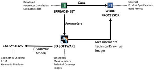
A SPREADSHEET forms the core of the methodology, which determines the value of the product parameters by reusing the design knowledge of the SME. The SPREADSHEET is linked to 3D SOFTWARE, where the product model is obtained. The geometric model can be exported to different CAE SYSTEMS for the validation of the solution. Data obtained from the SPREADSHEET and results of the CAD system (measurements, technical drawings, and images) are linked to a WORD PROCESSOR, in order to generate the product documentation.
Methodology: working procedure
A procedure for the development of a design assistant to generate bids for a particular SME is proposed in this section. The illustrates the different stages in its elaboration based on the architecture presented in the previous section.
Figure 2. Working procedure for developing a bid generator tool for a SME.
Source: The Author’s.
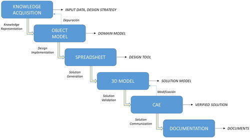
The procedure starts by acquiring knowledge regarding the strategies and methods of design used by the company, thereby capturing the “know-how” of the SME. The main objective is to identify the relevant data of the design problem: description of the product designed and its performance requirements, the requirements established by the customers (expressed as the necessary input data), and the design strategy (selection of the type of solution in terms of the requirements).
It is necessary to represent the acquired knowledge for two activities: (1) debugging of the model and its subsequent implementation; and (2) allowing the interpretation to be shared by the members of the SME, as experts in the particular field of design, and by the developers of the system. The product and design process models can be revised and debugged by the experts of the SME, and developers can understand them correctly to ease their implementation. An object-oriented approach was considered the best methodology for the knowledge representation system. Up to this point, the activities developed are independent of the implementation, which would allow its application with any method of design automation.
The established architecture implements the knowledge model on a spreadsheet, which constitutes a highly common tool for this type of activity. The main functions of this spreadsheet as a design assistant include enabling: input data from the customer to be entered and validated; selection of the type and the configuration of the solution; and calculation of the values of its various parameters.
The calculated properties describe the solution, and hence it is possible to generate the virtual model of the product in a 3D CAD tool. The model parameters are linked to cells of the spreadsheet. The virtual model enables the next stages of the design process to be developed: the verification of the solution through different CAE tools, the automation of the generation of technical documentation, both textual (e.g. bids, contract) and graphic (e.g. technical drawings, photorealistic images). The solution is validated and the customer clearly understands the solution and the conditions of the contract.
Each of these stages is described in greater detail in the following sections.
Knowledge acquisition
Knowledge acquisition is a well-documented activity in the field of knowledge engineering (Schreiber et al., Citation1993). The objective is to capture the knowledge used by an expert in a specific field in order to design a product, and to represent it explicitly and formally so that it can be computed. The paradox occasionally arises that the greatest experts in a field remain unable to describe the solution process. Different methods of acquiring knowledge can be found in Pahl and Beitz (Citation1996), such as that proposed in the present work.
The Knowledge Acquisition process can be summarized in the following steps:
Perform a series of interviews with the experts, using "think aloud" techniques:
Informal interviews: to become familiar with the domain concepts and with the decision-making in the design process.
Directed interviews: to attain an explicit model of the design process from the expert, and for its later comparison with traditional problems and new situations.
Structured interviews: for specific tasks and model debugging.
Formally present the knowledge model acquired from the expert to solve the design problem. The representation must be easily interpreted by the experts and the knowledge engineer, so that the system can be debugged and completed. The knowledge model is generated by the knowledge engineer from the analysis of the design process by the expert, through techniques of organization and formalization of knowledge.
Debugging, fine tuning and verification of the model through the resolution of design problems, and the comparison with the solutions proposed by the expert and generated by the knowledge model.
A very important aspect of the process of acquisition of knowledge is the establishment of the suitable granularity of the problem, whereby granularity is understood as the appropriate level of detail of the knowledge to solve the problem, for example, a detailed description of external products is not necessary, only sufficiently information to their selection. The basic goals of this methodology are summarized in the following points:
Concept and embodiment design, as defined in Pahl and Beitz (Citation1996), where each product is reflected along with the definition of its architecture (components and topology) and its main dimensions and functional features. The components can be differentiated into parts and standard parts. Object-oriented techniques are considered for the modelling process and heuristics are introduced to solve the problem design. Symmetry is taken as a requirement, and simplifies the modelling and subsequent implementation of the product
Detail design (Pahl & Beitz, Citation1996): establishment of methods to calculate the value of the parameters and the other properties (such as materials) of the ideal solution of the problem. For the sake of simplicity in the understanding and implementation of the system, the use of production rules based on heuristics is considered suitable, in addition to the mathematical and geometrical relationships.
Establishment of input data: identification of performances and requirements that are frequently requested by the customers. A computer-assisted input structure is considered to select the necessary data, where different properties of design are offered based on the basic properties initially established by the customer.
Establishment of an estimation of costs: development of a heuristic-based method to generate an initial budget based on input data values. An error less than 10% is sufficient.
Object model
The object-oriented methodology is used as a means to represent the design knowledge. Specifically, the Unified Modelling Language defined in Fowler (Citation1997) is applied to develop the class and object diagram of the relevant concepts in a domain.
Considering the knowledge as information in context, each class includes its attributes and operations, and the relations needed to represent the product and relevant information in the SME context. In order to facilitate the application of the methodology and the communication between the various tools, a simple high-level model has been developed. This model is based on the high-level concepts from engineering ontologies, such as SUMO (Suggested Upper Merged Ontology) (Pease, Citation2015) applied to MBSE (Model-Based Systems Engineering) (GFSE, Citation2015).
In the process of knowledge acquisition, the necessary attributes and operations are determined that represent each product and component and the relationships between them. The basic operations include assembly of the product, design of parts, and selection of standard/catalogued parts. For these operations, a flow diagram provides the most suitable representation since these remain easy to use and are more commonly found in the world of SMEs than the activity diagrams from UML or other more advanced methods.
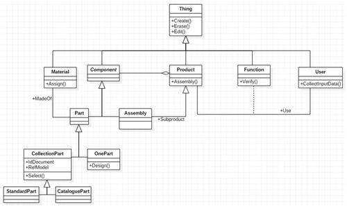
The high-level model is presented in below.
Figure 3. High-level class model.
Source: The Author’s.
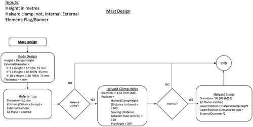
A flow diagram is shown in below. This illustrates the operation Design in the class Mast, to determine the values of the dimensional parameters and the presence of auxiliary features. The flow diagram has been developed in accordance with ISO 5807 (ISO, Citation2015).
Figure 4. Instance of a flow diagram for Mast design.
Source: The Author’s.
Spreadsheet
The knowledge obtained in the process of knowledge acquisition and represented by means of class and flow diagrams can be implemented in various ways: via programming macros or in the form of APIs, but, as suggested by previous experiences, using spreadsheets linked to 3D CAD applications provides the best option in the SME context.
The optimum method considers the implementation of all the knowledge in a single workbook, in order to prevent problems of synchronization between different files, and to manage and classify the information on different sheets, thereby facilitating its localization, recuperation and debugging.
The basic types of sheets include: a first sheet dedicated to the collection of input data and to the implementation of problem-solving procedures; a second sheet that develops an initial budget; and a number of sheets associated to the products (identified by fully capitalized letters "PRODUCT_N") and to parts (identified with the first letter in capitals and the order of the sheet in the workbook “Part_N”) to link the parameter values calculated in the workbook to their 3D models. When necessary, certain auxiliary sheets are created for specific tasks: for calculations or specific solving methods (such as using the Solver tool); using dynamic tables as a database; for connection to a database. The identification of the order of each sheet in the workbook facilitates their reference from the CAD tools. shows an example for a dining table design tool, where the data collection sheet, budget, main product, and the table top all appear.
Figure 5. Basic types of spreadsheet in the workbook for the assisted design tool.
Source: The Author’s.

The system could be enhanced with macros in the spreadsheet, but since programming expertise would be required, it is not recommended in the SME context. If macros are used, they should be included in the first spreadsheet.
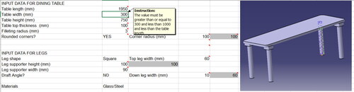
Once the application has been developed, the input data sheet must be the only sheet available to the user, since it features those cells that contain free parameters requested by customers. Therefore, the remaining sheets and cells must become write protected. In order to facilitate, complete and consistent input data by the user: data validation methods should be included (limitation of values and format validation); advice, recommendations and/or warnings should be provided for each parameter as appropriate in each case; and images should be included to ease the user’s comprehension of the parameters to be input and of the solutions attained. shows part of an input data sheet for the design tool of a dining table.
Figure 6. Input data sheet for design tool of a dining table.
Source: The Author’s.
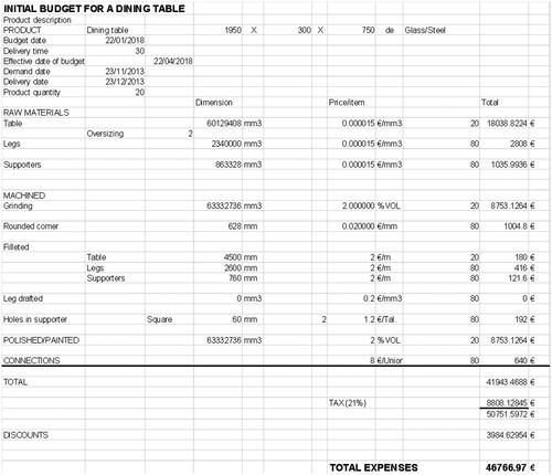
Based on the input data, the budget sheet must be able to generate an estimated cost for the product, with an error of less than 10% of the final cost. Since the basic dimensional data of the product is available, it is possible to estimate the volume of starting materials, the extensions of the manufacturing processes (in manufacturing, finishing, and heat treatments), and the cost of the assembly stages, packaging, and transport. In SMEs, this task is most commonly carried out using spreadsheet tools. The shows the sheet dedicated to setting out the estimated cost for a dining table:
Figure 7. Budget sheet.
Source: The Author’s.
The remaining sheets link the data generated in the design spreadsheet to the three-dimensional models developed in CAD. All of models contain the set of variables required to generate the final solution model. Product sheets contain assembly constraint data, and Part sheets contain the geometrical and dimensional data to describe the element. There are two types of parts: CollectionPart, where the set of dimensional values are fixed and each dimensional model must be selected; and OnePart, where the values are calculated from the input data in a design process. Mixed parts can be considered: these contain fixed data from a collection part, but some free values can also be calculated. For example, certain furniture modules have catalogued dimensions, but it remains possible to calculate specific values to fit the furniture to the dimensions of a room. The shows the head of a OnePart sheet.
Figure 8. OnePart sheet.
Source: The Author’s.
3D CAD model
A 3D model of the product in the CAD tool is developed using previously calculated data. Two steps are established: (1) the product is modelled, preferably using the variables considered in the object model and included in the spreadsheets; (2) the variables are then linked to the corresponding cells of the spreadsheet. In addition to dimensional values, variables can include string values, such as names or materials, or Boolean values, such as those that indicate the presence or not of certain components or the presence or not of certain features of parts (such as holes or ribs). A parametric variational approach is used, as defined in Benguria and Santos (Citation2008).
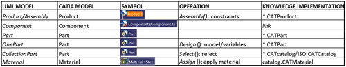
The shows the relationships between the model of the general object classes developed and implemented on the spreadsheets, and the CAD model, customised for the CATIA tool.
Figure 9. Relation table between UML model classes and features of CATIA.
Source: The Author’s.
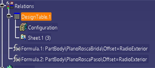
The CAD model must include the necessary variables to link the parameters present in the spreadsheets. The Design Table constitutes the means to link the spreadsheets and the 3D model. In order to reduce the number of variables to be linked, equations can be employed to compute the values of those calculable dependent variables, although this does hinder the debugging process.
In the CATIA specification tree, the includes the principal means to determine the parameters for the design of a mast: importation through design tables and calculation with the equations.
Figure 10. Design table and equations in CATIA specification tree.
Source: The Author’s.
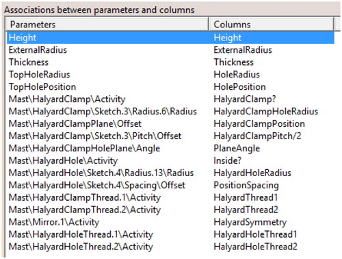
In order to facilitate comprehension, management, and debugging of the design assistant, the 3D model structure should coincide with the object-oriented product structure and the workbook structure, and the variables should keep their denomination in all models. shows the correlation between variables in the spreadsheet (Excel) and in the 3D model (CATIA) for the design of the mast.
Figure 11. Associations between parameters from CATIA (3D model) and columns from Excel (spreadsheet).
Source: The Author’s.
CAE analysis
Computer-aided Engineering Analysis is possible thanks to the creation of the model of the product, which grants a major advantage to the development of 3D models, among many other benefits. Two general situations can be considered:
The CAD tool includes analysis modules, for example for kinematic analysis (DMU Kinematics) or finite element analysis (Generative Structural Analysis) in CATIA. The model is used directly in those modules, since it is also an associative task, and hence the analysis can be reused with the different solutions obtained for each case.
The CAD tool does not include analysis modules. It is therefore necessary to ensure efficient communication between the CAD tool and the CAE tool. This means the identification and verification of the existence of adequate formats shared by the two tools, or the development of an interface. Ideally, both tools would produce collaborative work by means of interoperability techniques, but this could be excessively complex for SMEs (Benguria & Santos, Citation2008).
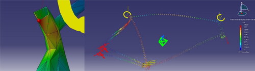
shows the results of finite element analysis developed in CATIA for the design of a customised bicycle frame. The results were verified with those obtained through traditional calculation methods.
Figure 12. FEA analysis results in CATIA for a bike frame.
Source: The Author’s.
Documentation
The principal documentation required to draft a commercial bid is that which allows the client to understand the solution, preferably in the form of graphic documentation, and the conditions of the contract, including the initial cost estimate and the product specification.
As in the previous stage, the graphic documentation is a consequence of the achievement of the 3D model and the associative character of the drawings. An advantage of this systems, it reflects the specific values of the design product on the technical drawings. In this case, most 3D CAD tools include a module for the automatic generation of technical drawings. The directly generated drawing is not perfect: as a general rule, these computer-generated drawings tend to require 1tweaking. 2modification. On the other hand, the drawing tool can be customised. An advantage for the client, it generates a photorealistic representation which help to fully understand the solution. The rendering techniques and the current visualization systems of 3D models, such as PDF3D (PDF3D, Citation2017), provide suitable means and they should therefore be integrated into the system and compatible or standard formats should be used. The results obtained on a system for the modular design of toys are shown in .
Figure 13. Technical drawing in CATIA and photorealistic representation in keyshot.
Source: The Author’s.

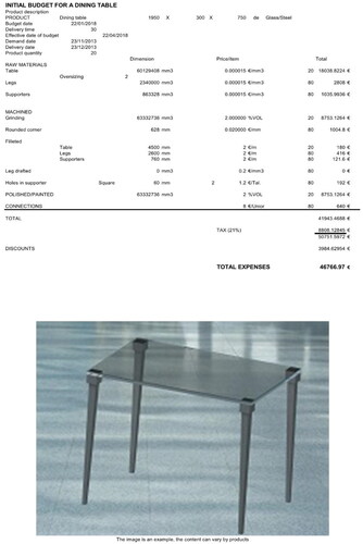
Textual documents can be obtained automatically from the data links and document templates, which constitute the more traditional methods of office tools. is an example of the estimated cost document for the dining table, generated in Excel.
Figure 14. Dining table budget from impression template in Excel.
Source: The Author’s.
Conclusions and challenges for the future
The proposed methodology has been achieved as a generalization of the development of the design automation tools for various use cases in the context of SMEs. This generalisation has required the inclusion of several fields of application (furniture, industrial, and construction), with diverse design goals, from the most functional and standardized designs, such as that of gear boxes, to the freest and most artistic ones, such as those found in the furniture sector. In other earlier studies, options different to those adopted in this methodology have been used:
In addition to class diagrams, two means have been utilised to represent the knowledge of the domain: ontologies and conceptual maps. The former has been considered excessively complex to learn and implement, and the latter remains appropriate only in the conceptual design stage.
In decision making, knowledge representation methods have been considered, such as decision trees, CRC (Class Responsibility Collaborator) (Beck & Cunningham, Citation1989), and other forms included in Chung and Stone (Citation1994) for regulatory knowledge. Initially, a number of these methods yielded suitable results and were easy to implement; however, in the debugging stage, the IF-THEN production rules proved more efficient. Two reasons for have been put forward: the reasoning in SME is expertise-driven, and production rules constitute the norm for SME staff. Similar criteria represent the workflow of the process design between traditional flowcharts versus the activity model of UML technology.
Various implementation methods have been tested for the development of design assistant tools: internal programming in 3D CAD tools (such as Knowledge modules of CATIA V5); development of API’s and macros with VBA (Visual Basic for Applications) Microsoft language in the 3D CAD tools (such as CATIA V5) and in spreadsheets (such as Excel); and the use of advanced calculation capacities of spreadsheets. Spreadsheets are more commonly used and are better-known in the context of SMEs.
The proposed solution must constitute a starting point for design automation in SMEs, but it must evolve, integrating more advantages of the current technological revolution. In developing the methodology, certain problems have been revealed which would be interesting to approach and solve. Several of these problems are presented below:
In order to assist the users in the development of their own models, a high-level general domain model has been created. In addition, it would be a sensible adjunct to create a general model of relationships and decision-making activities that would address at least 90% of those present. An exhaustive model is considered impossible for all different cases of use. Relationships can be assumed as: union, support, regulation, feeding, and manipulation. In the case of decision-making activities, these can be taken as: presence of components in a product or features in a part, determination of geometry or dimensions, and assignment of a property or relationship (such as material).
The maturation of this methodology, together with the new flexible manufacturing technologies of Industry 4.0, would allow more customised solutions in these assistant, one of the keys to SME productivity compared to large companies, as presented in Gangoiti et al. (Citation2021). In addition, an easier and assisted data input would allow clients to develop their own design process, progressing from assisted design to autonomous design, as presented in Chen et al. (Citation2021).
The results obtained from the CAE analysis, such as FEA, can be used to extract conclusions on behaviour. These conclusions can be expressed as rules of behaviour, similar to heuristics, and can be included as design rules in the design assistant tool. A clear example would be to perform a series of analyses with various dimensions, and to deduce from the results the ranges of validity of the dimensions as a function of the loads and spans.
The state of the art in CAE is oriented towards tasks of analysis of products and there are fewer tools for product design. A second utility of the design assistant tool is that it can be used to facilitate the generation of multiple solutions in keeping with the design criteria of the SME, for their later analysis and simulation. Shorter generation times and access to a greater number of solutions for analysis lead to optimal solutions. This tool has been tested for the design and simulation of internal combustion and turbofan engines. There are many researches in the spatialized literature to automate certain aspects of engineering design. They can be easily integrated into this methodology, such as the assisting systems for sustainability for SMEs presented in Kassem and Trenz, (Citation2020).
Finally, in order to improve the integration of the results of the design assistant tool with other applications specific to certain technological fields, it is necessary to enhance the interoperability. In (Yan et al., Citation2006) is proposed, that great advantages of commercial offers in SMEs are waited from this objective. In this regard, two developing lines have been considered: the use of standards; and the development of a mapping table with the optimal communication formats between various applications. Regarding the first line of development, the adoption of the STEP format (Standard for the Exchange of Product Data) in the field of engineering and the approach to BIM (Building Information Modelling) systems in the construction world is considered. In the second line of development, the most common applications in the world of SMEs are to be included in the mapping table of communication formats.
Disclosure statement
No potential conflict of interest was reported by the authors.
References
- Beck, K., & Cunningham, W. (1989). A laboratory for teaching object oriented thinking. ACM SIGPLAN Notices, 24(10), 1–6. https://doi.org/10.1145/74878.74879
- Beitz, P., Pahl, G., & Beitz, W. (1996). Engineering design: A systematic approach. Springer.
- Benguria, G., & Santos, I. (2008). SME maturity, requirement for interoperability. In Enterprise Interoperability III (pp. 29–40). Springer. https://doi.org/10.1007/978-1-84800-221-0_3
- Cederfeldt, M., & Elgh, F. (2005). Design automation in SMEs–current state, potential, need and requirements. In A. Samuel and W. Lewis (Eds.), DS 35: Proceedings ICED 05, the 15th International Conference on Engineering Design (exec. Summ.), full paper no. DS35_314.46. (pp. 248–249). https://doi.org/10.3316/informit.390095181685561
- Chavali, S. R., Sen, C., Mocko, G. M., & Summers, J. D. (2008). Using Rule based design in engineer to order industry: An SME case study. Computer-Aided Design and Applications, 5(1-4), 178–193. https://doi.org/10.3722/cadaps.2008.178-193
- Chen, H., Wen, Y., Zhu, M., Huang, Y., Xiao, C., Wei, T., & Hahn, A. (2021). From automation system to autonomous system: An architecture perspective. Journal of Marine Science and Engineering, 9(6), 645. https://doi.org/10.3390/jmse9060645
- Chung, P. W. H., & Stone, D. (1994). Approaches to representing and reasoning with technical regulatory information. The Knowledge Engineering Review, 9(2), 147–162. https://doi.org/10.1017/S0269888900006779
- Fowler, M. (1997). UML distilled: A brief guide to the standard object modeling language (Object Technology Series). Addison-Wesley.
- Fundación OPTI. (2007). Automatización Integral de la Empresa Industrial. Estudio de prospectiva. Ministerio de Industria, Turismo y Comercio. Depósito Legal: M-52.843-2007. http://www.opti.org
- Gangoiti, U., López, A., Armentia, A., Estévez, E., & Marcos, M. (2021). Model-driven design and development of flexible automated production control configurations for industry 4.0. Applied Sciences, 11(5), 2319. https://doi.org/10.3390/app11052319
- GFSE. (2015). Model-based system engineering (MBSE). http://mbse.gfse.de/
- ISO. (2015). ISO 5807:1985 Information Processing –Documentation Symbols and Conventions for Data, Program and System Flowcharts, Program Network Charts and System Resources Charts.
- Kassem, E., & Trenz, O. (2020). Automated sustainability assessment system for small and medium enterprises reporting. Sustainability, 12(14), 5687. https://doi.org/10.3390/su12145687
- Lee, B., Choi, H., Min, B., & Lee, D. E. (2020). Applicability of formwork automation design software for aluminum formwork. Applied Sciences, 10(24), 9029. https://doi.org/10.3390/app10249029
- PDF3D. (2017). PDF3D. https://www.pdf3d.com/
- Pease, A. (2015). Suggested upper merged ontology (SUMO). http://www.adampease.org/OP/
- Schreiber, G., Wielinga, B., & Breuker, J. (1993). KADS: A principled approach to knowledgebase system development (Vol. 11). Knowledge-Based System Academic Press.
- Strategic Direction (2005). Engineering automation for the SME: A Viable Tool for “Mass” customization. Strategic Direction, 21(1), 33–35.
- Yan, W., Pritchard, M., Chen, C., & Khoo, L. (2006). A strategy for integrating product conceptualization and bid preparation. The International Journal of Advanced Manufacturing Technology, 29(5), 616–628. https://doi.org/10.1007/s00170-005-2552-x