Abstract
During the growth of sago palm (Metroxylon sagu Rottb.), primary suckers appear from the main stem (MS) of transplanted suckers. Then, secondary suckers appear from the primary suckers. After the MS (trunk) is first harvested 10 and several years after transplantation, trunks can be harvested persistently using the primary, secondary, and subsequent suckers, which are designated as derivative suckers, growing with the MS. However, little knowledge exists about the growth behavior of derivative suckers. This study clarified how derivative suckers, especially the primary and secondary suckers, spread in the horizontal direction, and how they form a plant with the MS during the creeping growth stage. Most derivative suckers crept in the direction of about 70° subtended by the mother stem. However, two primary suckers that appeared early after transplantation crept in an obtuse angle to the creeping direction of the MS. As the reason for this obtuse angle direction, we considered the following four factors: (1) the existence of petiole, (2) distance from the sucker to the ground surface, (3) enlargement of the MS, and (4) space for sucker growth. The growth behaviors of the two primary suckers and the other derivative suckers differed. Therefore, in sago palm cultivation, the two primary suckers which appeared first from the MS were very important for formation of the framework of the plant with the MS, in terms of efficient utilization of space for the growth of derivative suckers.
Sago palm (Metroxylon sagu Rottb.) growing in near-equatorial regions in Southeast Asia and Melanesia accumulates a large amount of starch in its trunk. In addition, sago palm can grow in humid peat soil with low pH without soil amendment such as drainage and soil pH, suggesting the possibility of maintaining soil environment and avoiding competition for farmland with other crops. Therefore, sago palm recently has received much attention as a starch crop mainly for use as an industrial raw material (Kainuma, Citation2015). Large-scale production of sago palm at plantations has just begun in Indonesia (Jong, Citation2015). Furthermore, the expansion of production and the development of new farms are anticipated for the future.
Sago palm can be propagated mainly by suckers: branches from the creeping mother stem that can be raised as seedlings (Sato et al., Citation1979). The transplanted sucker goes through the creeping growth stage, when the main stem (MS) elongates horizontally along the ground surface. It reaches the trunk formation stage, at which time which the stem elongation shifts from horizontal to vertical (Nabeya et al., Citation2015b). In the creeping growth stage, daughter suckers (primary suckers) appear from the MS. The secondary suckers appear from the primary suckers with plant growth. For this report, we designate all suckers derived from the single MS, such as primary and secondary suckers, as ‘derivative suckers.’ Derivative suckers also go through the creeping growth stage and then reach the trunk formation stage, as does the transplanted sucker. Although the sago palm trunk (MS) is first harvested 10 and several years after transplantation, trunks of derivative suckers, mainly primary suckers, can be harvested 2–3 years after first harvest if these suckers are managed appropriately with the MS. Because numerous derivative suckers appear continually, one can harvest numerous trunks over a long period. Therefore, thinning out extra derivative suckers appropriately, known as sucker control, is necessary to let them grow healthily (Nabeya et al., Citation2013). Flach (Citation1977) proposed a method of sucker control by which all derivative suckers appeared from transplanted suckers were thinned out for two years after transplantation. Then, from three years after transplantation, one derivative sucker was grown every two years. He also calculated the trunk harvesting interval on the assumption that the growth behavior of derivative suckers was the same as that of the MS. However, the actual growth behavior of derivative suckers has remained unknown. Although Irawan et al. (Citation2015) reported changes in the survival rates, plant height, and leaf number of derivative suckers by generation order on the MS in a plant (clump), the creeping growth of the suckers was not clarified. Little scientific knowledge exists to characterize their growth behavior. To control the number of derivative suckers appropriately, it is necessary to observe the growth behavior of derivative suckers accurately. Our objectives are to clarify how derivative suckers, especially the primary and secondary suckers, spread in horizontal direction, and how they form a plant with the MS during the creeping growth stage.
Materials and methods
The investigation was conducted in a sago palm garden in Mukah, Sarawak, Malaysia (02° 56′ 31.4″ N; 112° 18′ 26.6″). The spineless type of sago palm, which is widely cultivated in Sarawak, was used. Suckers were raised in a nursery according to conventional methods and were transplanted in a field on 2 September 2005.
The distances separating planting rows and plants were, respectively, 6 m and 5 m. Considering the topography, the space between planting rows actually was 4.6–7.2 m (avg. 6.0 m). The space between plants was 2.9–7.1 m (avg. 5.1 m). The area occupied by one plant was 30.6 m2 on average, and the plant density was 327 plants ha−1. Cultivation management was conducted according to local conventional methods without fertilizer application.
We arranged an experimental section (25 × 21 m) where 20 plants grew in the field. We investigated their growth 5 times during 2011–2014. The terms of each part and their positions in this investigation are presented in Figure . We pushed a glass fiber pole in the ground to touch the end of the MS (Figure (a)), and established it as the reference point, signifying the transplantation position. This point was referred to as OM (Figure (b)). In primary and secondary suckers, the positions attached to its mother stem were established, respectively, as OP and OS. Primary and secondary suckers were designated, respectively, as Sn and Sn−m. Actually, n and m are shown in the order of attached positions from the end of mother stem: for example, the primary sucker, which stands closest to OM, was designated as S1. The secondary sucker which stands the nearest to OP of S1 (Op−S1) was designated as S1−1. The secondary sucker which stands the second nearest to OP−S1 was designated S1−2.
Figure 1. Base of the MS (a) and an upper view of the MS (b) at about one year after transplantation. MS stands for main stem. Blue pole in (a) and the star symbol in (b) show the reference point (OM). S1 and S2 are primary suckers that appeared from MS; OP–S1 and OP–S2 denote the appearance positions from MS. ▶▶▶ indicates the creeping direction of MS. Rosy arrows indicate the creeping directions of S1 and S2.(a): Rosy dashed line ( – ) shows the creeping part of MS and (b): dS1 and dS2, respectively, denote the distances from OM to OP–S1 and OP–S2. θS1 and θS2 are angles of their creeping direction subtended by the creeping direction of MS.
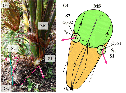
The lengths in the creeping part of primary and secondary suckers (dSn, dSn−m, respectively) were defined, respectively, as the horizontal distance from OP or OS to the growth point judged by appearance.
The creeping direction angles of S1 and S2 were measured, respectively, as θS1 and θS2, as presented in Figure (b). The creeping direction angles of S3 and so on were measured by the same method above. A sign test was employed for analysis of creeping direction among suckers.
Results
Growth of the primary sucker
The base of the MS and its diagram at about one year after transplantation are presented in Figure . The MS elongated separating from OM by its creeping growth. Two primary suckers (S1 and S2) appeared and grew in the attaching parts of petioles 0.20 m apart from OM. Generally, 2–3 primary suckers appeared at one year after transplantation. Assuming the side of the growth point, an angle of 0° on the axis of the creeping direction of MS, S1, and S2 crept to the direction of the arrows. These suckers were distant from MS. Positions at which primary suckers appeared were gradually distant from OM with creeping growth of MS. The creeping direction of primary suckers differed for every sucker.
Figure presents the relation between the distances (dSn in Figure (b)) from the positions where each primary sucker appeared to OM and the angles of their creeping direction. For 0.15–0.50 m from OM, approximately half of the primary suckers crept in an obtuse angle to the creeping direction of MS. These primary suckers tended to form a larger angle nearer OM. However, primary suckers that appeared more than 0.50 m distant from OM fundamentally crept in an acute angle direction. Figure shows the frequency distribution of the appearing position every 0.05 m from OM in primary suckers. Many primary suckers appeared and grew in the range of 0.15–0.20 m. The appearance frequency of primary suckers tended to be smaller in locations distant from OM.
Figure 2. Relation between the distance from appearance positions of each primary sucker to OM and the angles of their creeping direction. n = 131.
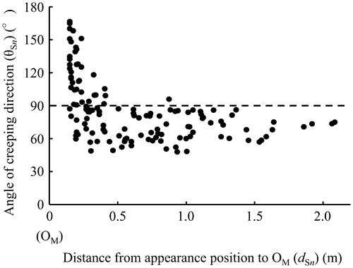
Figure 3. Frequency distribution of appearance positions in primary suckers. The frequency distribution is shown every 0.05 m from OM. n = 131.
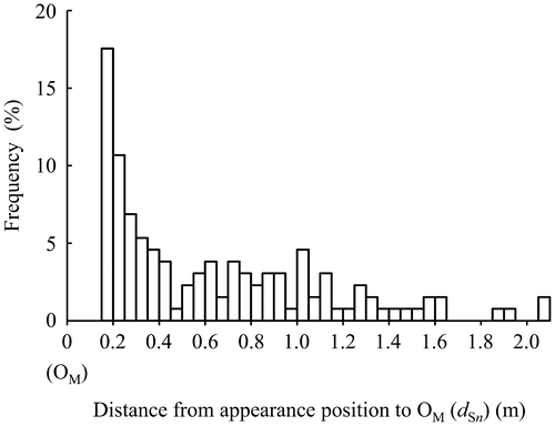
Figure presents the relation between the order of appearance positions of primary suckers on MS and the angle of their creeping direction. S1 crept in the direction of 132 ± 23° (average ± SD). S2 crept in the direction of 102 ± 21°; its angle was significantly smaller than S1 at 5% level by Tukey’s test. The angles from S3 to S8 were almost constant at 71 ± 13°. They were significantly smaller than S2 at 5% level by Tukey’s test.
Figure 4. Relation between the order of appearing positions of primary suckers on MS and their creeping direction. Error bars show the standard deviation. The same letter represents no significance at the 5% level by Tukey’s test.
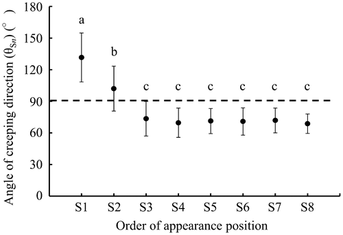
Figure shows a diagram of the creeping direction subtended by MS and the length in creeping part of primary suckers. In this figure, the creeping direction of MS was regarded as 0° and the side on which S1 attached was regarded as positive angle and the opposite side S1 attached was regarded as negative angle. Most of S2 crept in the direction opposite to S1 across the creeping direction of MS. As a result of a sign test regarding the directionality of S1 and S2, significant regularity at 1% level was recognized, suggesting that S2 significantly creeps in the direction opposite to S1. However, for S3 and S4, no significant regularity was found, suggesting that these suckers creep at both positive and negative angles irrespective of the creeping direction of S1.
Figure 5. Diagram of the creeping direction and the length in the creeping part of primary suckers. The side attached S1 is regarded as a positive angle. Dashed lines ( – ) show the creeping direction of MS. The thick solid line (—) shows the creeping direction and the length of the primary sucker. Circles around OM, respectively, denote 1.0 m and 2.0 m in distance from OM.

Growth of the secondary sucker
Figure presents the relation between the distance from appearance positions of each secondary sucker to OP and the respective angles of their creeping directions. The angles of creeping direction of each secondary sucker subtended by creeping direction of their mother stem (primary sucker), were basically acute angle at 70 ± 13°, irrespective of the distance from OP.
Figure 6. Relation between the distance from appearing position of each secondary sucker to OP and the angles of their creeping direction. *Indicates S2–1 of plant D presented in Figure . n = 110.
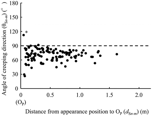
Figure portrays a diagram of the creeping direction subtended by primary suckers and the length in the creeping part of secondary suckers. In this figure, the creeping direction of their mother stem was regarded as 0° and the side on where Sn-1 attached regarded as positive angle. The length was represented with a logarithmic scale and the outside circle and the inside circle denoted 1.0 m and 0.1 m in distance from OP, respectively. Here, Sn−2, Sn−3, and Sn−4 crept both sides irrespective of the creeping direction of Sn−1. No significant regularity of the creeping direction was found by a sign test.
Figure 7. Diagram of the creeping direction and the length in the creeping part of secondary suckers. The side on which Sn-1 was attached was regarded as a positive angle. The dashed line ( – ) shows the creeping direction of the mother stem. The thick solid line (—) shows the creeping direction and the secondary sucker length. The length is represented with a logarithmic scale. The outside circle and the inside circle around OP, respectively, denote 1.0 m and 0.1 m in distance from OP.

Distribution of suckers in the experimental section
Figure depicts seven plants (A–G) including the MS of the transplanted sucker and derivative suckers in a part of experimental section at about nine years (3,250 days) after transplantation. All MS reached the trunk formation stage or the trunk elongation stage. They formed a trunk at the place on average of 1.82 m distance from OM. In the plant D, S2 reached the trunk elongation stage. It formed a trunk at 1.66 m distance from OP−S2.
Figure 8. Growth behavior of MS and derivative suckers in a part of experimental section at about nine years after transplantation. Circles denote the positions of MS and derivative suckers which expanded leaves. The circle size denotes the stem or trunk diameter. Gray circles denote MS and derivative suckers from the trunk formation stage to the trunk elongation stage. A star denotes the reference point (OM). The thick line ( – ) and the fine line (―), respectively, show the creeping parts of MS and derivative suckers.
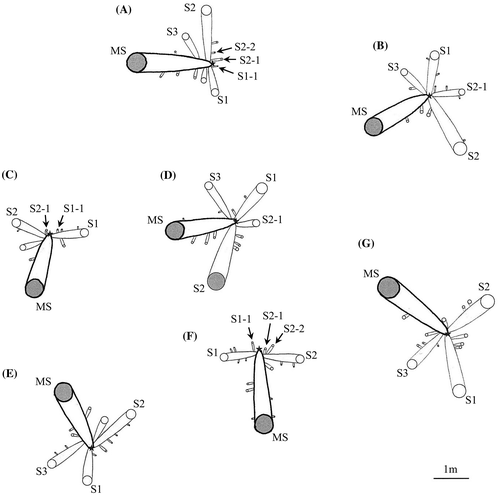
Judging from the relation among creeping direction of MS, S1, and S2, it was considered that the framework of the plant has approximately two types: Y-shape type and T-shape type though there were types between Y-shape and T-shape types. Here, we considered plant B, D, E, and G to be Y-shape type and plant A, C, and F to be T-shape type. This observation suggests that the three of MS, S1, and S2 basically formed the framework of the plant. In Y-shape type, S3 crept in the space between MS and S1. In plants B and D of Y-shape type, S2−1 crept in the space between S1 and S2. S2−1 of plant B was larger among secondary suckers, and three third suckers appeared from it. These third suckers crept in the space between S2−1 and S1 or S2. S2−1 of plant D (*: depicted in Figure ) also grew larger. This sucker crept in the obtuse angle direction subtended by S2 and the opposite direction to MS (an angle of 176°). In plants of T-shape type, secondary suckers crept in the opposite direction to MS. In plants A and F of T-shape type, three secondary suckers of S1−1, S2−1, and S2−2 crept in the opposite direction to MS. Assuming the creeping direction of MS 0° and the side attached S1 positive angle, S1−1, S2−1, and S2−2 crept in the directions of −175°, −172°, and −171° in plant A and 173°, −163°, and −141° in plant F to MS, respectively. In plant C of the T-shape type, two secondary suckers of S1−1 and S2−1, respectively, crept in the directions of −161° and −173° to MS. Consequently, derivative suckers which appeared near OM crept radially around OM.
Discussion
Although many primary suckers appear from the MS during their growth, the appearance frequency of primary suckers tended to be smaller in locations distant from OM (Figure ). Nabeya et al. (Citation2015a) reported that sucker buds were generally initiated at every node in suckers for transplantation. Practically, however, a small number of suckers which developed and appeared were observed in sago palm garden. Further studies are needed to clarify the factors decreasing the appearance frequency of primary suckers.
The derivative suckers fundamentally crept in the direction of about 70° subtended by the mother stem, except S1 and S2 (Figures and ). We inferred that the stem formation was related as a factor to determine the creeping direction of derivative suckers during the creeping growth stage. In the creeping growth stage, sago palm stems were formed by the horizontal line of thin disciform internodes with an angle of about 40° for the ground (Nabeya et al., Citation2015b). Consequently, the nodes at which leaves attached also incline to an angle of about 40° for the ground. Because half of the bottom of creeping mother stem is buried under the ground, daughter suckers differentiated in the underside of mother stem fundamentally cannot appear, whereas daughter suckers differentiated in the upper and lateral sides can appear. When daughter suckers appear on the upper side of mother stem, they do not creep and grow at the position where they appeared generally. These daughter suckers grow slowly and do not become larger immediately. However, when daughter suckers appeared in the lateral part of stem, they creep with its growth. Figure presents the part where leaves attach in the creeping growth stage. Sago palm leaves attach as the bases of petioles overlapped. Therefore, the creeping direction of daughter sucker was limited and the daughter sucker would creep in an acute angle direction subtended by creeping direction of the MS. In addition, the possibility was considered that the existence of derivative suckers which appeared and grew previously was expected to limit the creeping direction of derivative suckers which appeared later.
Figure 9. Area where leaves attach in the creeping growth stage. The white arrow indicates the creeping direction of the mother stem. The dashed line (—) shows the estimated nodal plane. The dashed arrow indicates the creeping direction when the daughter sucker appeared.
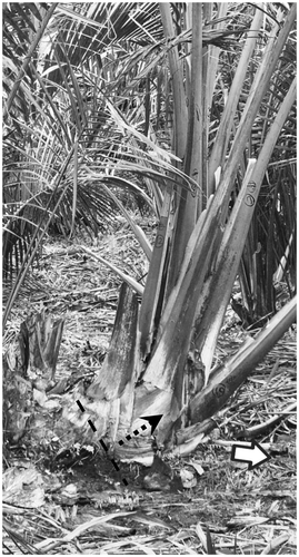
However, S1 and S2, which were the primary suckers appearing within short period after transplantation, crept in an obtuse angle direction to the creeping direction of the MS (Figures and ). As the reason for this obtuse angle direction of S1 and S2, we considered the following four factors: (1) the existence of petiole, (2) the distance from the sucker to the ground surface, (3) enlargement of the MS, and (4) the space for sucker growth. (1) The existence of petioles: within short period after transplantation, because the sago plant size is smaller, it was considered that there was little influence of petioles on sucker growth developed from the sucker bud. Some old leaves of suckers are removed before raising seedlings. During growth after transplantation, old leaves die and fall off from the outside, as presented in Figure . Therefore, the creeping directions of primary suckers that appeared within short period after transplantation were not limited by petioles. Suckers such as S1 and S2 were able to creep in the obtuse angle direction. (2) The distance from the sucker to the ground surface: early after transplantation, the distance between the upper side on the creeping part of the MS and the ground surface is small (Figure (a)). If S1 and S2 were to appear from the upper side on the creeping part, adventitious roots that emerged from each primary sucker would reach the ground and grow in it. As such, the suckers on the upper side on the creeping part could creep like primary suckers appearing from the lateral side on the creeping part. (3) Enlargement of the MS: the creeping part of MS enlarges rapidly with its growth from transplantation. The higher node diameter is greater than that of the node at which the primary sucker appeared. Consequently, the MS becomes an inverted circular cone shape. In addition, leaf petioles surrounding these suckers in the early growth stage are not thicker than those which attach at a higher node position. Therefore, a primary sucker, such as S1 and S2, which appeared at the upper and the lateral side on creeping part of MS, creeps easily opposite to the creeping direction of the MS. (4) The space for sucker growth: when S1 and S2 appear, there is no primary sucker except S1 and S2. There is more space for sucker growth opposite to the creeping direction of the MS.
Flach (Citation1977) proposed a method of sucker control by which all appearing derivative suckers were thinned out during two years after transplantation. However, the growth behavior of S1 and S2, which appeared during early growth, exhibited different characteristics from those of other derivative suckers, as described above. Therefore, we inferred the importance of S1 and S2 remaining without thinning out in terms of efficient utilization of space by the growth of derivative suckers. Their stems creep in three directions around OM, forming a Y-shaped or T-shaped framework by making these primary suckers grow with the MS. Generally, sucker control starts at around four years after transplantation. At this time, the derivative suckers which are made to grow with the MS are selected by thinning based on the framework of plant structured since transplantation. Especially, in T-shaped plants, the secondary suckers appearing first from S1 or S2 are important because there is no primary sucker creeping opposite direction to the MS. Therefore, in T-shaped plants (A, C, and F) as presented in Figure , management is necessary to enhance the growth of S1−1, S2−1, and S2−2.
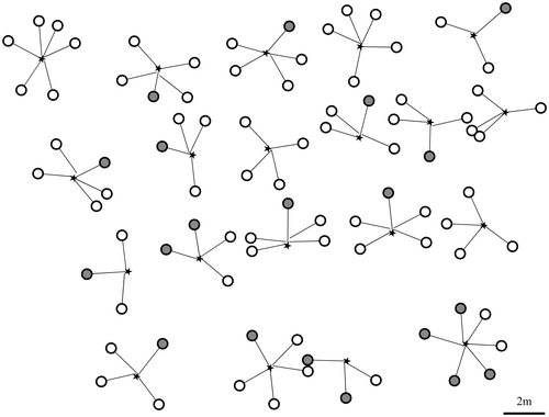
Consequently, in sago palm cultivation, primary suckers that appear first from the MS, such as S1 and S2, are extremely important to form the framework of plant with MS. The plant framework has approximately two types: Y-shape type and T-shape type. In a T-shaped plant, secondary suckers creeping in the opposite direction to the MS are important. These suckers should be retained without thinning out, even though Flach (Citation1977) recommended removal of all suckers during two years after transplantation. Actually, one farmer skilled in sago cultivation, a particularly innovative farmer, did not thin out these secondary suckers (Nabeya et al., Citation2013). Figure shows the distribution of trunks of the MS and the distribution of the predicted position of trunks of derivative suckers based on the actual positions of growing suckers in the experimental section of this report. In this figure, assuming trunk size of larger suckers creeping before the trunk formation, and assuming that they are the same trunk size of the suckers after the trunk formation, their diameter and length were designated, respectively, as 55 cm and 1.8 m. Derivative suckers that appeared early after transplantation basically crept radially from the reference point. Based on this predicted distribution, we inferred the necessity of conducting sucker control considering the angle and the creeping distance so that suckers of adjacent plants did not mutually block up their creeping directions. From this garden, the MSs are expected to be harvested in 2017. Primary suckers are expected to be harvested about 2–3 years after harvesting of MSs. Under appropriate sucker control, we can expect stable production of trunks over a long period by harvesting numerous derivative suckers.
Figure 10. Distribution of trunks of MS and prediction position of trunks of derivative suckers. The gray circles show the positions of suckers that already formed a trunk. White circles show the prediction positions of suckers forming a trunk. The star denotes the reference point (OM). The circle size and the length from OM were estimated from the size of suckers that already formed a trunk.
Abbreviations:
MS – the main stem of transplanted sucker; OM – the reference point, which is the end of the main stem of transplanted sucker; OP – the position at which a primary sucker attached to the main stem; OS – the position at which a secondary sucker attached to the main stem; Sn – the n-th primary sucker from the end of the main stem; Sn−m – the m-th secondary sucker from the end of the n-th primary sucker stem.
Disclosure statement
No potential conflict of interest was reported by the authors.
Acknowledgments
We are also grateful for the assistance of Mr. Smith and his family in Malaysia.
Funding
This work was supported by JSPS KAKENHI [grant number 20405017] and by a grant for research abroad from Miyagi University, Japan.
References
- Flach, M. (1977). Yield potential of sago palm and its realization. In M. A. Tankooling (Ed.), Sago’76: Papers of the first international sago symposium, Kuching, Sarawak, July 5–7, 1976 (pp. 157–177). Kuala Lumpur, Malaysia.
- Irawan, A. F., Yamamoto, Y., Miyazaki, A., Yoshida, T., & Jong, F. S. (2015). Changes in the vegetative growth of sago palm (Metroxylon sagu Rottb.) suckers from different generation orders in a clump. Tropical Agriculture and Development, 59, 50–56.
- Jong, F. S. (2015). The current state of sago palm harvesting and cultivation methods. In The society of Sago Palm Studies (Ed.), The sago palm -the food and environmental challenges of the 21st century- (pp. 157–164). Kyoto: Kyoto University Press.
- Kainuma, K. (2015). Potential uses of sago starch. In The Society of Sago Palm Studies (Ed.), The sago palm -the food and environmental challenges of the 21st century- (pp. 289–295). Kyoto: Kyoto University Press.
- Nabeya, K., Nakamura, S., Akama, M., Nakamura, T., Nitta, Y., Watanabe, M., Goto, Y. (2013). Analysis of the effect of the sucker-control in the sago palm (Metroxylon sagu Rottb.) cultivation. In Proceedings of Second ASEAN Sago Symposium, Kota Samarahan, Sarawak, Oct. 29–31, 2012, (pp. 50–52). Malaysia: UNIMAS.
- Nabeya, K., Nakamura, S., & Goto, Y. (2015a). Position and development of differentiated lateral buds in sago palm (Metroxylon sagu Rottb.). Plant Production Science, 18, 435–442.10.1626/pps.18.435
- Nabeya, K., Nakamura, S., Nakamura, T., Fujii, A., Watanabe, M., Nakajima, T., … Goto, Y. (2015b). Growth behavior of sago palm (Metroxylon sagu Rottb.) from transplantation to trunk formation. Plant Production Science, 18, 209–217.10.1626/pps.18.209
- Sato, T., Yamaguchi, T., & Takamura, T. (1979). Cultivation, harvesting and properties of sago palm. Japanese Journal of Tropical Agriculture, 23, 130–136*.