
 ?Mathematical formulae have been encoded as MathML and are displayed in this HTML version using MathJax in order to improve their display. Uncheck the box to turn MathJax off. This feature requires Javascript. Click on a formula to zoom.
ABSTRACT
In steel structures, the greater energy dissipation capacity of a beam-column connection means greater seismic performance. Increasing energy dissipation of the slip of cantilever beam splices is an effective method of improving the energy dissipation capacity of beam-column connections. This paper provides a study of an “upper flange welded-lower flange bolted” (UWLB) beam-column connection with slotted holes. The UWLB connection is a new type of the beam-column connection, whose upper flanges and lower flanges of the splicing area have different splicing methods, the upper flanges welded while the lower flanges bolted. Six finite element models were established to analyze the effects of the different slotted hole dimensions on energy dissipation capacity. The results show that the energy dissipation of the splicing area increases with the increase of slotted hole dimensions, and the connections have greater rotational capacity. The energy dissipation ratio of the splicing area is more than 37.7%, the ratio increases with the increase of the slotted holes dimensions. The UWLB connections with slotted holes achieved 0.06 rad rotation under the cyclic loading. The UWLB connection with slotted holes has greater rotational capacity and higher energy dissipation capacity of the splicing area than the normal UWLB connection.
1. Introduction
Industrialization is the direction for constructions of residential buildings. With the development of the industrialization, steel structures have been widely used in the residential buildings as good kind of prefabricated structures. In assembly steel structures design, the beam-column connection is an important part of the design. During the Northridge Earthquake in 1994 (Mahin Citation1998, 263) and the Kobe Earthquake in 1995 (Horikawa and Sakino Citation1996, 182), a large number of rigid beam-column connections of steel structures suffered brittle damage. It was found that the rigid beam-column connections of steel structures have poor deformation capacity, poor ductility and poor seismic performance, so that the connections are prone to suffering brittle damage during earthquakes, causing economic losses and safety threats. For this problem, researchers have analyzed the seismic performance of the beam-column connection and proposed improvement measures.
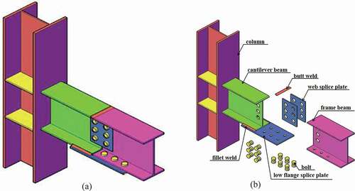
One effective way to avoid the brittle damage of the beam-column connection is to move the plastic hinge away from the beam end. There are two traditional methods of moving the plastic hinge away from the beam end: reducing the beam section and reinforcing the beam end. The different reduced beam section connections were carried out and plate-reinforced steel moment-resisting connections were researched, this connections dissipated energy through the plastic deformation of the plastic hinge so as to avoid brittle damage of the beam-column connections in earthquakes (Yang, Li, and Yang Citation2009, 1335; Lee and Kim Citation2007, 531; Chambers, Almudhafer, and Stenger Citation2003, 389; Pachoumis et al. Citation2009, 223; Kim et al. Citation2002, 490). Arul Jayachandran S. et al. and Ali Abolmaali et al. proposed that the beam-column connection should be designed as the semi-rigid connection to allow the plastic deformation under severe earthquakes (Arul Jayachandran et al. Citation2009, 449; Abolmaali et al. Citation2009, 1196). The method that bolts instead of welds are used for the beam-column connection was proposed. And the connection could dissipate energy by the slip and the plastic deformation (Guo et al. Citation2016, 13; Liu et al. Citation2017, 373). The studies of the connections with slotted holes are provided. The connections with slotted holes provided better ductility, higher plastic deformation capacity and increased load–resisting capacities near the ultimate strength (Shu, Ma, and He Citation2016, 12; Hou et al. Citation2018, 665). In recent years, there are more and more studies of the column-tree connection which can not only move the plastic hinge away from the beam end but also realize the assembly. Zhang Ai-lin et al. carried out cyclic loading tests and finite element analyses on Z-type cantilever beam splices of column-tree connections. This connection is the fabricated connection and it can move the plastic hinge away from the beam end. The analyses showed that the connections could effectively dissipate energy by the slip between friction surfaces (Zhang, Guo, and Liu Citation2017, 110). However, in the process of some building construction, the column-tree connections which are connected by bolts have the bolt bulges on the upper flange, causing the inconvenience of installing floors. For example, these bulges will bring inconvenience to the construction when the steel bar of the floor is tied up. Finally, through the research results mentioned above, a UWLB beam-column connection was put forward. Its upper flange of the cantilever beam and upper flange of the frame beam are connected by butt weld, while lower flanges are connected by a splice plate. The splice plate is connected to the cantilever beam by fillet welds and connected to the frame beam by bolts, as shown in . The installation of the floor slabs is convenient because the upper flange surface of this connection is flat.
In order to improve the energy dissipation capacity and the rotational capacity of the UWLB connection, a method in which the slotted holes are used for the lower flange splice plate and the web splice plates was proposed. Six finite element models were established by the finite element analysis software ABAQUS in order that the effects of different slotted hole dimensions on the energy dissipation capacity could be analyzed.
Figure 1. The UWLB beam-column connection.
2. Design of specimen
2.1. Dimensional parameters of specimens
The details of the specimens are shown in and . Referring to the Standard for design of steel structures and Code for seismic design of buildings, a three-story steel frame has been designed to determine the details of the UWLB beam-column connection. The connection is taken from the side column connection of the second-floor frame in the 3-story frame structure. The breadth and depth of the frame are 6 m and 6 m, respectively. Considering the deadweight of beams, columns and roofs, the standard value of permanent load is 4.0 kN/m2, and the standard value of live load is 2.0 kN/m2. Through calculations, it is determined that the columns are H-shaped H250 × 250 × 9 × 14, and the beams of specimens are H-shaped H300 × 150 × 8 × 12. The length of the columns is 1.3 m, the length of the frame beams is 1.05 m and the length of the cantilever beams is 0.3 m.
Under the design load, the static design has been conducted according to the design of equal bearing capacity. The beam flange undertakes bending moment M, and the beam web undertakes shearing force V. Through calculations, it is determined that the dimensions of each component in the splicing area and the number of the bolts, which is given by EquationEquations (1(1)
(1) )–(Equation4
(4)
(4) ). The size of the lower flange splice plate is 430 × 170 × 10 mm, and that of the web splice plates are 200 × 250 × 8 mm. The number of the bolts of the web splice plate and the flange splice plate both is 6. The bolts of specimens are 10.9-grade M20 friction type high-strength bolts whose pretension force is 155 kN. It is predicted that the slip between the splice plate and the lower flange is large because the bolt holes of the lower flange splice plate are slotted holes. In order to avoid the premature compression between the cantilever beam and the frame beam during the loading process, the spacing between the cantilever beam and the frame beam is 20 mm.
Static design:
In which nwb is the bolt number of web splices; nFb is the bolt number of lower flange splices; Abnw is the net cross-sectional area of the beam web which deducts the bolt holes (mm2); NvbH is the shear strength of one high-strength bolt (kN); Ibn is the moment of inertia of net cross-sectional area of the beam which deducts the bolt holes (mm4); Ib0 is the moment of inertia of section of the beam (mm4); nFp is the bolt number of unilateral-flange of the beam; dFb is the diameter of the bolt hole of the beam flange (mm); tFb is the thickness of the beam flange (mm); Hb is the height of the beam section (mm); twb is the thickness of the beam web (mm); dwb is the diameter of the bolt hole of the beam web (mm); yi is the vertical distance between each bolt and the center of the bolt group (mm); Wbn is the net cross-sectional modulus of the beam which deducts the bolt holes (mm3); fv is the shear strength of the steel (N/mm2); f is the design value of tensile strength of the steel (N/mm2).
The seismic design includes three aspects: seismic bearing capacity checking calculation of beam-column connection (EquationEquation (5)(5)
(5) ), ultimate bearing capacity checking calculation of rigid beam-column connection (EquationEquations (6
(6)
(6) )–(Equation8))
(8)
(8) and checking calculation of the panel zone (EquationEquationEquation (9)
(9)
(9) )
(9)
(9) .
Seismic design:
In which Wpc and Wpb are plastic section modulus of columns and beams, respectively (mm3); fyc and fyb are the yield strength of columns and beams, respectively (N/mm2); N is the axial force at the top of the column (kN); Ac is the cross-sectional area of columns (mm2); η is the coefficient, which is taken here as 1.05; Muj is the ultimate flexural capacity of the connection (kN m); ηj is the connection coefficient, which is taken here as 1.3; Mp is the plastic moment capacity (kN m); Mufj is the ultimate flexural capacity of the beam flange (kN m); Muwj is the ultimate flexural capacity of the beam web (kN m); Vuj is the ultimate shear capacity of the connection (kN); ln is the net span of the beam (mm); VGb is the shear design value of beam end analyzed by simply supported beam under the representative value of gravity load (kN); Mb1 and Mb2 are the bending moments of the beams on both sides of the panel zone, respectively (kN m); Vp is the volume of the panel zone (kN); γRE is the seismic adjustment coefficient of bearing capacity of panel zone, which is taken here as 0.75.
Figure 2. Detail of the UWLB connection.
Figure 3. Detail of upper flange of splicing area.
2.2. Parameter design
Six specimens including one normal UWLB connection and five slotted-bolted UWLB connections were devised by changing the dimension of the slotted holes of the lower flange splice plate and the web splice plates. The detail of the slotted hole is shown in . The composition of the slotted hole is divided into two parts: half circle part and straight segment part. The diameter of the half circle part is 22 mm, which is the standard diameter of an M20 high-strength bolt hole. The way to change the dimension of the slotted holes is realized by changing the length of the straight segment. The specific control parameters of the specimens are shown in . And the “l”, is the length of the straight segment.
Figure 4. Detail of slotted hole.
Table 1. Control parameters of the specimen.
2.3. Calculation of finite element results
The calculation diagrams of moment-rotation hysteretic curves of the connection and splicing area are shown in and .
Figure 5. Diagram of bending moment and rotation. (a) Diagram of bending moment. (b) Diagram of rotation.
Figure 6. Diagram of the relative rotation angle of splicing area.
The calculation equations of bending moment and rotation in this paper are given by EquationEquations (10(10)
(10) )–(Equation12
(12)
(12) ).
In which M is the moment at the intersection point between the column and the beam (kN m); M1 is the bending moment of the splicing area (kN m); L is the distance between the beam free end and panel zone center (mm); L1 is the distance between the beam-free end and the cantilever beam end (mm); L2 is the distance between the cantilever beam end and the panel zone center (mm); F is the load of the beam free end (kN); θ is the rotation angle of the connection (rad); θ1 is the relative rotation angle between the cantilever beam and the frame beam (rad); Δ2 and Δ1 are horizontal displacements on the upper and lower sides of the panel zone, respectively (mm); Δ4 and Δ3 are the vertical displacements on the left and right sides of the panel zone, respectively (mm); hbf is the distance between the center line of the upper and lower flanges of the beam (mm); hcf is the distance between the center line of the upper and lower flanges of the column (mm); Δ5 and Δ6 are the horizontal displacements of the upper flange of cantilever beam and the upper flange of frame beam in splicing area, respectively (mm); Δ7 and Δ8 are the horizontal displacements of the lower flange of cantilever beam and the lower flange of frame beam in splicing area, respectively (mm).
3. Construction of FEM model
3.1. Model establishment
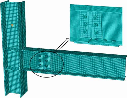
The finite element models were established by the finite element analysis software ABAQUS. The model is subdivided into the base parts of one column, one cantilever beam, one frame beam, twelve bolts, four stiffeners, two web splice plates and one flange splice plate. These base parts of models are made up of C3D8I (an 8-node linear brick, incompatible modes). Referring to the results from experiments and theoretical analyses, the high-stress parts used a local mesh refinement approach. Special care must be taken for the modeling of the bolts, due to its thread and dissimilarities between bolt heads and nuts. To simplify the model a uniform shank diameter was considered, equal to the effective diameter of the bolt thread, which is critical for the overall strength of the bolt. One finite element model is shown in .
Figure 7. Finite element model.
3.2. Boundary conditions and material constitutive parameters
Appropriate constraints were used to define the interaction of the models. The surface-to-surface contact with finite sliding was employed. The penetration between the contacted components was restricted by using “Hard Contact” in the normal direction. The tangential characteristic of the contact was simulated by selecting the penalty friction formulation. The normal contacts of the surface-to-surface interactions between the bolt cap and the web splice plate, the bolt shanks and the hole walls, the bolt cap and the lower flange of the frame beam, the bolt cap and the flange splice plate, the web and the web splice plate, the lower flange and the flange splice plate were defined as “hard contact”, and the tangential contact were defined as the penalty friction contact with friction coefficient which is 0.4. The 300 kN axial pressure was applied to the top of the column. The lateral restraint was applied near the end of the beam to prevent the beam from torsional-flexural buckling during the loading process.
The finite element analyses involve the plastic development of the materials and the large deformation of the beams, which belong to the problems of material nonlinearity and geometric nonlinearity. The corresponding parameter settings in ABAQUS finite element analyses are as follows: An isotropic type material was chosen with the bilinear stress-strain law and the isotropic hardening rule. The well suited for steel elements Von Mises yield criterion was adopted. When the Mises stress of the steel exceeded the yield stress of the steel, the plastic deformation would occur. The material constitutive parameters of the steel, the bolt and the weld are shown in . Where E is the Elastic modulus; ν is the Poisson’s ratio; σy is the yield stress; σµ is the ultimate stress; εy is the yield strain; εµ is the ultimate strain.
Table 2. Materials performance indices.
3.3. Loading system of specimens
The loading system in this paper referred to AISC. The loading system is the variable amplitude loading mode system, using the inter-story drift angle to calculate the loading displacement. Loading downwards is positive and loading upwards is negative. The specific loading system is shown in . In this paper, the loading process was divided into three steps: the first step, applying the pretension force of bolts; the second step, applying the axial pressure to the top of the column; and the third step, applying the cyclic displacement.
Table 3. Loading system of specimens.
3.4. Verification of FEM
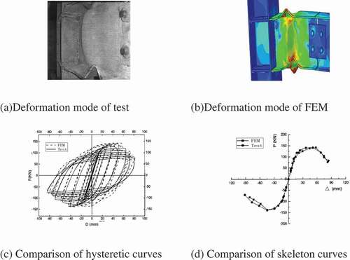
To verify the accuracy of finite element analyses in this paper, the specimen which already tested was analyzed by the same finite element modeling method as this paper. The analysis results are shown in . The model is made up of C3D8I (an 8-node linear brick, incompatible modes). The constitutive model for steel of specimens is based on experimental data, σy = 296.8 N/mm2, εy = 0.14%, E = 2.05 × 10⁵ N/mm2, σu = 470.0 N/mm2, εu = 18.0%, εst = 26.4%. All the components were meshed in hexahedron shape by means of sweep technique and followed a medial axis algorithm, which guarantees meshes of high quality. In order to get reliable results with less computational time, the fine mesh was created at the region with big stress, whereas the coarse mesh was created at the region with less stress. The boundary conditions of the specimens are in agreement with those of the tests. The top of the column was connected with the reaction wall through horizontal strut, and the 850 kN axial pressure was applied on the top of the column. The bottom of the column was connected with the ground through a hinge. The beam end of the specimen was attached to an MTS hydraulic ram to exert cyclic loading. In order to avoid the lateral buckling of the beam, a lateral bracing was also employed.
,) is the deformation mode of the finite element model and the test specimens, respectively. The comparison shows that the deformation modes of the finite element model are consistent with those of the test. Both the flange and the web have excessive local deformation and convexity. ) is the comparison of hysteretic curves and skeleton curves, respectively. It is easy to see that they fit with each other well. We can conclude that the model established in the article is able to mimic the mechanical behavior of connection under the cyclic loading.
Figure 8. Verification of FEM. (a) Deformation mode of test. (b) Deformation mode of FEM. (c) Comparison of hysteretic curves. (d) Comparison of skeleton curves.
4. Analysis of FEM results
4.1. Stress nephogram and failure mode
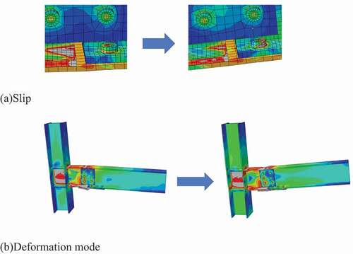
The stress nephogram and the deformation mode of the SH3 were taken as an example to analyze the stress state and the deformation of the connection under cyclic loading, as shown in . The whole stress process of the connection can be divided into three stages: elastic stage, elastic-plastic stage and plastic stage. At the initial stage of the loading process, the connection is in the elastic stage that the connection has no obvious deformation. With the loading displacement increases, the micro-bulging deformation occurs at the lower flange splice plate. When the inter-story drift angle reaches 0.04 rad, now that the bending moment of the splicing area is larger than the slip bending moment between friction surfaces, the slip occurs in the lower flange splice, as shown in ). With the increase of the slip, bolt shanks and holes start to extrude and the bearing capacity is further improved. In reverse loading, the deformation of the lower flange splice plate has slow recovery, but the lower flange splice plate still has residual deformation. This phenomenon indicates that the connection is in the elastic-plastic stage. As the loading displacement increases, the connection starts to step into the plastic stage due to the compression between bolt shanks and bolt holes and expansion of the plastic zone, as shown in ). The main plastic deformation of the specimens is concentrated in the splicing area. The connection can effectively move the plastic hinge away from beam-column connection and avoid brittle failure. The lower flange splice plate of the RH1 damages during the second cycle of loading to 0.05 rad; the lower flange splice plate of the SH1 damages during the first cycle of loading to 0.06 rad; the lower flange splice plate of the SH2 damages during the second cycle of loading to 0.06 rad; while that of the SH3, the SH4 and the SH5 successfully load to 0.06 rad. The results showed that the rotational capacity of the connection improves with the increase of the slotted holes dimensions.
Figure 9. Stress nephogram of connection. (a) Slip. (b) Deformation mode.
4.2. Analysis of hysteretic curve
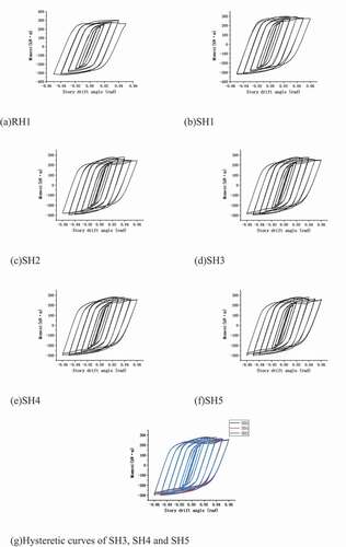
The moment-rotation hysteretic curves of the connections are shown in . According to the hysteretic curves, because of the different splicing methods of the upper and lower flanges, the connections present a geometric asymmetry and the hysteretic curves also present the asymmetry. At the initial stage of the loading process, specimens are in the elastic stage that the moment-rotation hysteretic curves change linearly and symmetrically. The slip occurs at the lower flange splices with the increase of the load–displacement. Meanwhile, the bearing capacity basically keeps the constant tendency with the increase of the story drift angle so that the curves present platform segments. After the platform segments, the moment-rotation hysteretic curves show an upward trend because the specimens begin to step into the strengthening stage due to the compression of bolt shanks and holes. The connections dissipate energy by the plate deformation, and the bearing capacity continues to improve. Compared with the traditional-welded beam-column connections, the hysteretic curves of the UWLB beam-column connections with slotted holes have obvious slip platform segments. Compared with bolted beam-column connections, the hysteretic curves of UWLB beam-column connections with slotted holes are fuller than the bolted beam-column connections. The results clearly showed that the connections exhibit good hysteretic curves with a stable and saturated shape, which indicate that the connections have good seismic performance.
According to the moment-rotation hysteretic curves, it can be seen that the length of the platform segments increases obviously with the increase of the slotted holes dimensions (). The platform segment of the normal UWLB connection is not obvious and the normal UWLB connection damages at the loading to 0.05 rad. The connections with slotted holes have achieved 0.06 rad rotation under cyclic loading. This value is much higher than the plastic rotation limit of 0.03 rad, which is commonly used to differentiate between ductile and brittle connections for moment-resisting frames. In conclusion, the UWLB connections with slotted holes have greater rotational capacity and higher energy dissipation capacity of the splicing area than the normal UWLB connection. For the six specimens, the slip load of every cycle decreases constantly, because the lower flange splice plate yield during the loading process, the slip load decrease with the lower flange splice plate yield.
Figure 10. Hysteretic curves of beam-free end. (a) RH1. (b) SH1. (c) SH2. (d) SH3. (e) SH4. (f) SH5. (g) Hysteretic curves of SH3, SH4 and SH5.
4.3. Skeleton curve
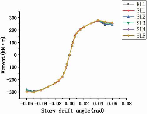
The skeleton curves of six specimens were compared and analyzed, as shown in . It can be seen in that the skeleton curves of six specimens are basically in coincidence at the elastic stage, the difference of the initial rotation stiffness is not huge. The skeleton curves of specimens are all in S-shaped. The connections have different splicing methods at the upper and lower flanges so that the skeleton curves are not symmetrical. The skeleton curves increase linearly before specimens yield, but it shows nonlinear characteristics after specimens yield. In addition, after reaching the ultimate load, the bearing capacity of the RH1 decreases the fastest and that of the SH5 decreases the slowest. This phenomenon indicates that the larger the slotted holes are, the slower the bearing capacity of the specimen decreases. The slotted holes increase the energy dissipation of slip and reduce the deformation energy dissipation of plates. To a certain extent, the slotted holes protect the lower flange splice plate, slowing down the downward trend of bearing capacity.
Figure 11. Skeleton curves.
4.4. Analysis of energy dissipation capacity
The energy dissipation capacity of the connections was expressed by the equivalent viscous damping coefficient–. The calculation formula and the calculation diagram are shown in EquationEquation (13)
(13)
(13) and , and the calculation results are shown in .
Figure 12. Calculation diagram of equivalent viscose damping coefficient.
Table 4. Equivalent viscose damping coefficient and energy dissipation.
It can be seen that the equivalent viscous damping coefficient increases with the increase of the loading displacement, which shows that the energy dissipation capacity improves and the connection begins to dissipate energy by the deformation and the slip. The equivalent viscous damping coefficient and the total energy dissipation of the SH5 are the largest so that the energy dissipation capacity of the SH5 is the best. The slip and the rotational angle increase with the increase of the slotted holes dimensions, the slotted holes delay the failure of the connections and improve the energy dissipation capacity of the connections. The smaller the slotted holes dimensions are, the earlier the specimens are damaged. Comparing with the SH3, SH4 and SH5, it can be found that the total energy dissipation of the connections increases with the increase of the slotted holes dimensions, but the increase is very small. This is because the energy dissipation of the connections in the late loading process is mainly provided by the plastic deformation of the lower flange splice plate and the slip of the splice plate. The larger the dimension of the slotted holes, the more energy dissipated by the slip, but the energy dissipated by the plastic deformation of the lower flange splice plate will be reduced. In practical engineering design, the lower flange splice plate section can also be appropriately enlarged to improve the bearing capacity and energy dissipation capacity of the connection.
4.5. Analysis of the hysteretic curve of splicing area
By calculating the relative rotation angle (EquationEquationEquation (12)(12)
(12) )
(12)
(12) and the bending moment (EquationEquationEquation (10)
(10)
(10) )
(10)
(10) of the splicing area, the moment-rotation hysteretic curves of the splicing area are drawn, as shown in . The relative rotation angle of the splicing area removed the effects of the panel zone deformation, the beam deformation and the column deformation, which only included the splice plate deformation and the slip deformation of the splicing area. From the hysteretic curve of the splicing area, it can be seen that the positive rotation angle of the splicing area is much larger than its negative rotation angle. From the calculation method of the relative rotation angle of the splicing area, it can be seen that when the rotation angle of the splicing area is positive, the specimen is in the negative loading process. When the specimens are in the positive loading process, the cantilever beam contacts with the frame beam after the slip and plate deformation, and the relative rotation angle of the splicing area of the specimens cannot continue to increase. When the specimens are in the negative loading process, the relative rotation angle of the splicing area can continue to increase with the increase of plate deformation and bolt holes deformation. Therefore, the positive rotation angle of the splicing area is much larger than the negative rotation angle. The rotational deformation of the connections can be regarded as the relative rotation of the frame beam and the cantilever beam around the butt weld of upper flanges.
Figure 13. Hysteretic curves of splicing area. (a) RH1. (b) SH1. (c) SH2. (d) SH3. (e) SH4. (f) SH5.
4.6. Analysis of energy dissipation in splicing area
The total energy dissipation of the connections under cyclic loading is divided into four parts: the deformation energy dissipation of beams, the deformation energy dissipation of columns and the deformation energy dissipation of panel zone, the energy dissipation of the splicing area. The energy dissipation of the splicing area is divided into the energy dissipation due to frictional slip and the plastic deformation energy dissipation of the lower flange splice plate. The calculation results are shown in . The energy dissipation of the splicing area is the sum of the area of the moment-rotation hysteretic curves of the splicing area during the whole loading process. The hysteretic curve of the splicing area is integrated by mathematical analysis software, and the energy dissipation of the splicing area is obtained.
Table 5. Energy dissipation calculation results of specimens.
It is easy to see that the energy dissipation ratio of the splicing area of the UWLB connections with slotted holes is more than 37.7%, which indicate that the connections with slotted holes have greater energy dissipation capacity and the connections can effectively dissipate energy by the slip and the deformation of the lower flange splice plate. The energy dissipation ratio of the UWLB connections with slotted holes is far larger than that of the normal UWLB connection so that the slotted holes can effectively improve the energy dissipation capacity of the connection. The energy dissipation ratio of the splicing area increases with the increase of the slotted holes dimensions. The slotted hole dimensions change from 2 mm to 10 mm in this paper, within which the slotted holes increase 2 mm, the proportion of energy dissipation of the splicing area increases by about 0.3% ~ 1.8%. Slotted holes are helpful to improve the energy dissipation capacity and rotational capacity of the connections, preventing connections from being damaged in rare earthquakes. However, too large rotation angle has a negative impact on the deformation and bearing capacity of the whole structure. Therefore, in practical design, a suitable dimension of slotted holes can be determined by calculation, which can not only ensure the greater energy dissipation capacity of the connections but also ensure that the deformation and bearing capacity of the whole structure meet the standard requirements.
5. Conclusions
Six finite element models including one normal UWLB connection model and five slotted bolted UWLB connection models were established by finite element analysis software ABAQUS. The effects of the different slotted hole dimensions on energy dissipation capacity were analyzed in this paper. The following conclusions are drawn:
It is concluded that the different splicing methods at the upper and lower flanges generate the distinctive seismic performance of the UWLB connection. Compared with the traditional-welded beam-column connections, the hysteretic curves of the UWLB beam-column connections with slotted holes have obvious slip platform segments. Compared with bolted beam-column connections, the hysteretic curves of UWLB beam-column connections with slotted holes are fuller than the bolted beam-column connections. The connections exhibit good hysteretic curves with a stable and saturated shape, which indicate that the connections have greater energy dissipation and seismic performance.
The failure mode of the UWLB beam-column connections with slotted holes is the buckling failure of lower flange splice plate, which effectively makes the plastic hinge move away from the beam-column connection and avoids brittle failure. The UWLB beam-column connections with slotted holes have stronger rotational capacity than the normal UWLB connection, achieving 0.06 rad rotation under cyclic loading, which is much higher than the plastic rotation limit of 0.03 rad. The proportion of the energy dissipation in the splicing area of the UWLB connections with slotted holes to the total energy dissipation is above 37.7% which is far larger than that of the normal UWLB connection. The energy dissipation of the slip and the proportion of energy dissipation in the splicing area increase with the increase of slotted hole dimensions. The slotted holes change from 2 mm to 10 mm in this paper, within which the slotted holes dimensions increase 2 mm, the proportion of energy dissipation in the splicing area increases by about 0.3% ~ 1.8%.
Under the earthquake, the UWLB beam-column connection with slotted holes can effectively dissipate energy by the slip of the splicing area, the deformation of the splice plate and the compression between bolt shanks and holes. Using the slotted holes can effectively improve the energy dissipation capacity and rotational capacity of the connection. The UWLB connection with slotted holes has greater rotational deformation capacity and energy dissipation capacity.
Disclosure statement
No potential conflict of interest was reported by the authors.
Additional information
Funding
References
- Abolmaali, A., A. Kukreti, A. Motahari, and M. Ghassemieh. 2009. “Energy Dissipation Characteristics of Semi-rigid Connections.” Journal of Constructional Steel Research 65 (5): 1187–1197. doi:https://doi.org/10.1016/j.jcsr.2008.05.014.
- AISC/ANSI 341–10. 2011. Seismic Provisions for Structural Steel Buildings. Chicago, IL: American Institute of Steel Construction.
- Arul Jayachandran, S., V. Marimuthu, P. Prabha, S. Seetharaman, and N. Pandian. 2009. “Investigations on the Behaviour of Semi-rigid Endplate Connections.” Advanced Steel Construction 5 (4): 432–451.
- Bursi, O. S., and J. P. Jaspert. 1997. “Benchmarks for Finite Element Modeling of Bolted Steel Connections.” Journal of Constructional Steel Research 43: 17–42. doi:https://doi.org/10.1016/S0143-974X(97)00031-X.
- Chambers, J. J., S. Almudhafer, and F. Stenger. 2003. “Effect of Reduced Beam Section Frames Elements on Stiffness of Moment Frames.” Journal of Structural Engineering 129 (3): 383–393. doi:https://doi.org/10.1061/(ASCE)0733-9445(2003)129:3(383).
- Gantes, C. J., and M. E. Lemonis. 2003. “Influence of Equivalent Bolt Length in Finite Element Modeling of T-stub Steel Connections.” Computers & Structures 81: 595–604. doi:https://doi.org/10.1016/S0045-7949(03)00004-X.
- GB50011-2010. 2010. Code for Seismic Design of Buildings. China Architecture & Building Press.
- GB50017-2017. 2017. Standard for Design of Steel Structures. China Architecture & Building Press.
- Guo, X., Y. Zhang, Z. Xiong, and Y. Xiang. 2016. “Load-bearing Capacity of Occlusive High-strength Bolt Connections.” Journal of Constructional Steel Research 127: 1–14. doi:https://doi.org/10.1016/j.jcsr.2016.07.015.
- Horikawa, K., and Y. Sakino. 1996. “Damages to Steel Structures Caused by the 1995 Kobe Earthquake.” Structural Engineering International 6 (3): 181–182. doi:https://doi.org/10.2749/101686696780495617.
- Hou, Z. X., C. Gong, Y. Zhang, Y. Z. Sun, J. Jiang, and G. Q. Li. 2018. “Seismic Behavior of Bolted Connections with Slot Bolt Holes at Ambient and Elevated Temperature.” Advanced Steel Construction 14 (4): 651–667.
- Kim, T., A. S. Whittaker, A. S. J. Gilani, V. V. Bertero, and S. M. Takhirov. 2002. “Experimental Evaluation of Plate-Reinforced Steel Moment-Resisting Connections.” Journal of Structural Engineering 128 (4): 483–491. doi:https://doi.org/10.1061/(ASCE)0733-9445(2002)128:4(483).
- Lee, C.-H., and J.-H. Kim. 2007. “Seismic Design of Reduced Beam Section Steel Moment Connections with Bolted Web Attachment.” Journal of Constructional Steel Research 63 (4): 522–531. doi:https://doi.org/10.1016/j.jcsr.2006.06.030.
- Lin, X., T. Okazak, K. Hayashi, and M. Nakashima. 2017. “Bolted Built-Up Columns Constructed of High-Strength Steel under Combined Flexure and Compression.” Journal of Structural Engineering 143 (2): 04016159. doi:https://doi.org/10.1061/(ASCE)ST.1943-541X.0001648.
- Liu, X. C., S. H. Pu, A. L. Zhang, and X. X. Zhan. 2017. “Performance Analysis and Design of Bolted Connections in Modularized Prefabricated Steel Structures.” Journal of Constructional Steel Research 133: 360–373. doi:https://doi.org/10.1016/j.jcsr.2017.02.025.
- Mahin, S. A. 1998. “Lessons from Damage to Steel Buildings during the Northridge Earthquake.” Engineering Structures 20: 261–270. doi:https://doi.org/10.1016/S0141-0296(97)00032-1.
- Pachoumis, D. T., E. G. Galoussis, C. N. Kalfas, and A. D. Christitsas. 2009. “Reduced Beam Section Moment Connections Subjected to Cyclic Loading: Experimental Analysis and FEM Simulation.” Engineering Structures 31 (1): 216–223. doi:https://doi.org/10.1016/j.engstruct.2008.08.007.
- Shu, Z., R. Ma, and M. He. 2016. “Comprehending the Ductile Behavior of Slotted Bolted Connections.” The Structural Design of Tall and Special Building 26 (3): 1–13.
- Swanson, J. A., D. S. Kokan, and R. T. Leon. 2002. “Advanced Finite Element Modeling of Bolted T-stub Connection Components.” Journal of Constructional Steel Research 58: 1015–1031. doi:https://doi.org/10.1016/S0143-974X(01)00098-0.
- Yamaguchi, E. 2009. “Practical Finite Element Procedure for Achieving Mesh Objectivity in Local Buckling Analysis of Steel Structures by Beam Elements.” Advanced Steel Construction 5 (3): 224–236.
- Yang, Q., B. Li, and N. Yang. 2009. “Aseismic Behaviors of Steel Moment Resisting Frames with Opening in Beam Web.” Journal of Constructional Steel Research 65: 1323–1336. doi:https://doi.org/10.1016/j.jcsr.2009.01.007.
- Zhang, A., Z. Guo, and X. Liu. 2017. “Seismic Performance of Z-type Cantilever Beam Splices of Column-tree Connection.” Journal of Constructional Steel Research 133: 97–111. doi:https://doi.org/10.1016/j.jcsr.2017.02.009.