
 ?Mathematical formulae have been encoded as MathML and are displayed in this HTML version using MathJax in order to improve their display. Uncheck the box to turn MathJax off. This feature requires Javascript. Click on a formula to zoom.
ABSTRACT
Rapid development of long-span urban transportation hubs arouses higher requirements of structural design methods. However, the current design codes do not give effective provisions of the equivalent uniform live load for long-span transportation hubs. A revised equivalent uniform live load is developed by considering the aspect (length-to-width) ratio of the one-way slab system for the urban transportation hubs. The most unfavorable loading positions of the bus tires are determined, and the equivalent uniform live load is computed by using the Chinese Load Code. The structural response under equivalent uniform live load is further compared to that under actual load, then the original equation of the equivalent uniform live load with the Chinese Load Code is revised by considering the aspect ratio of one-way slab. An actual engineering computation of equivalent uniform live load is carried out. The results reveal that the calculation methods of the Chinese Load Code cannot reflect the force transmission characteristics of the small-area tire load on the one-way slab. The structural responses under the revised equivalent uniform load are in good agreement with that under the actual load. The revised calculation method is suitable for most areas in this urban transportation hub and similar structures.
1. Introduction
In recent years, with the acceleration of China’s urbanization process and economic development, the vehicle number is increasing rapidly, and the urban traffic congestion is becoming common. To address this issue, The Central People’s Government of the People’s Republic of China (Citation2013) decided to support the development of urban transportation hubs that can integrate bus departure, transfer, parking, and arrangement. In those urban transportation hubs (as shown in ), people can park their private cars in the hub and transfer to the urban core area by buses (Clifton et al., Citation2014; Aixia Citation2013). The features of such urban transportation hub are: (1) the hub is subjected to the buses that have a large volume (the length of the bus is about 18 m) and a large weight (about 27 t); (2) the column spacing and the slab span are also larger than the usual parking lot buildings. The bus load is the main source of the live load for the urban transportation hub, which makes the calculation method of bus load becomes a key issue (Conroy and Tumialan Citation2015; Keyvani and Sasani Citation2015). The calculation methods of slab system in urban transportation hub mainly include three methods: arranging uniform load in the whole area, arranging specific load at the most unfavorable position, and calculating and arranging equivalent uniform load according to structure, and they will be introduced in the next three paragraphs. Whichever method is selected, the design of the hub slab should achieve the balance between the structural safety and economy (Kamjoo and Eamon Citation2018; Junyuan, Deng, and Wei Citation2017). Therefore, the rational calculation method of the live load for the urban transportation hub is of great importance in structural design.
Figure 1. A prototype of urban transportation hub

The existing design specifications in national standards provide some provisions about the live load of buses. ASCE7-16: Minimum Design Loads for Buildings and Other Structures (ASCE7-16, Citation2016) proposes the regulations in Tables 4–. The minimum uniformly distributed the live load of the garages is 1.92kN/m2 for passenger vehicles only. And for trucks and buses, the design work should obey AASHTO LRFD Bridge Design Specification (AASHTO Citation2012). This specification also stipulates that bus loads are converted to lane line loads. These national standard methods are not precise and not suitable for the urban transportation hubs.
Table 1. Dimensions of FE models
Eurocode 1: Actions on structures Part1-1: General actions: Densities, self-weight, imposed loads for buildings (EN1991-1-1, Citation2002) proposes specification in section 6.3.3 of the European Standard. The urban transportation hub can be classified as Category G. The loads are composed of a single axle load Qk (it may be selected within the range 40 to 90kN) and a uniformly distributed load qk (5.0kN/m2). The axle load should be applied to two squares with 200 mm×200 mm at the most unfavorable loading positions, and the spacing between two squares is 1.8 m. Similarly, the Loading for buildings Part1 Code of practice for dead and imposed loads (BS6399: Part1: Citation1996, Citation1996) proposes that urban transportation hub shall be classified as Category G. The live load should be determined according to specific use, and the load is applied on a square contact with a side length of 50 mm. These national standard methods are accurate and complicated but not straightforward and suitable for structural designers.
According to the Chinese Load Code for the design of building structures (GB50009-Citation2012, Citation2012), when the vehicle design load is 300 kN, the following rules should be complied. The uniform live load of a vehicle is 35 kN/m2 when the one-way slab span is greater than 2 m or the two-way slab span is more than 3 m. And the uniform live load of a vehicle is 20 kN/m2 when the two-way slab span is more than 6 m. When the above-mentioned conditions are not met, the tire load of the buses should be converted into an equivalent uniform live load according to the equivalent principle of the structural responses.
The calculation method of equivalent uniform live load has already attracted attentions from researchers. These studies mainly focus on some factors including slab span, thickness of cover soil (Le et al., Citation2018), number of buses, the aspect (length-to-width) ratio of the two-way slab (Zhong, Hongmei, and Zhonghua Citation2011), column spacing (Bin, Guodong, and Jimin Citation2017), and different slab systems (Xin et al. Citation2019), etc. However, few studies focus on the equivalent uniform live load for the slab systems of the urban transportation hubs (Duvanovaa, Bubnova, and Romanovich Citation2016). Many urban transportation hubs built or under construction are still designed by original code method, however, the applicability of original code method is open to doubt. Improper use of calculation method of equivalent uniform live load may lead to security risk (Nifu and Haitan Citation2019; Yang et al. Citation2018). Therefore, it is necessary to propose an improved calculation method.
In this paper, the most unfavorable loading positions of the buses are firstly determined by applying different arrangements of the bus loads to slab system in the urban transportation hubs. Then, the structural responses under the equivalent uniform live load are computed according to the current provisions of the Chinese Load Code. The calculated responses are compared with those under the actual bus loads. Last, the revised equivalent uniform live load calculation method, which consider the aspect ratio of the one-way slab, is proposed.
2. Finite Element (FE) analysis for the most unfavorable arrangement
2.1. Buses loads
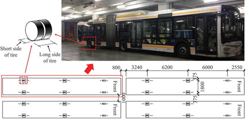
According to the site investigations in most urban transportation hubs of China, buses are mainly divided into two types: one is the ordinary bus with a length of 12 m, and the other is Bus Rapid Transit (BRT) with a length of 18 m. BRT shown in is of interest in this study. The total weight of the BRT is 280kN, of which the front axle weighs 65kN, the center axle weighs 100kN, and the rear axle weighs 115kN. Because the center and rear axles are heavy, one axle of them has two tire groups and one group has two tires side by side, while the front axle has also two tire groups which have only one tire at one end (). The number of tires mentioned in the article is the number of tire groups. The dimensions of tire projection on the center axle and the rear axle are 0.6 m × 0.2 m, and the dimensions of tire projection on the front axle are 0.2 m × 0.2 m. The long side of the projection is perpendicular to the driving direction of the BRT, and the short side of the projection is parallel to the driving direction of the BRT. As shown in , the spacing between the front axle and the center axle is 6 m; the spacing between the center axle and rear axle is 6.2 m; the transverse spacing of tire groups is 1.8 m; the front and rear spacing between BRTs is at least 0.8 m; the left and right spacing between BRTs is at least 1 m.
Figure 2. 18 m BRTs size and layout (unit: mm)
2.2. Most unfavorable loading positions
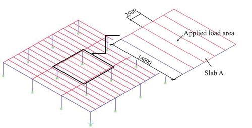
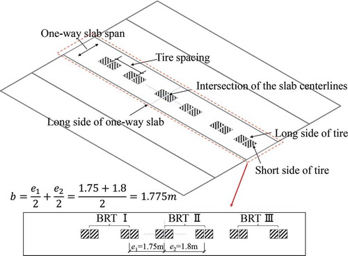
According to the Chinese Load Code, the calculation method of equivalent uniform live load for the slab is to convert the bus load with the most unfavorable loading position into a uniform live load. Due to construction convenience, the existing urban transportation hubs of China basically adopt the one-way slab system. shows a simplified FE model of a one-way slab system in the urban transportation hub. A group of one-way slabs compose five one-way slabs whose length are 14.6 m, and width are 2.5 m (as shown in ). The models are established by using FE package SAP2000. The beams and slabs are simulated by using beam and shell elements, respectively. To reduce boundary effect, there are three spans in each direction in the FE models and the columns are set as rigid bodies.
Figure 3. FE model (unit: mm)
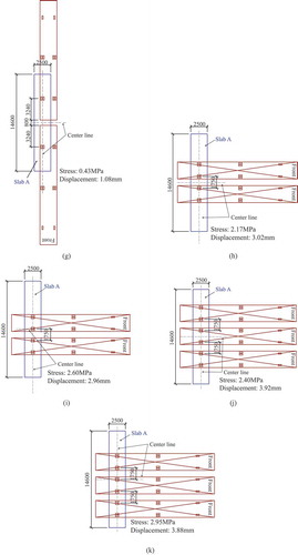
As shown in , the loads of one, two, or three BRTs are applied to one-way slab A in the middle span to determine the most unfavorable loading position, and eleven cases of BRT arrangements are taken into account. The mid-span bottom stress (tension stress is positive) and vertical displacement (downward displacement is positive) of slab A are calculated and shown in . The results indicate that the structural responses of slab A when the driving direction of the BRT parallels to the slab span are more than those when the driving direction is perpendicular to the slab span. The structural responses reach the maximum when the rear tires are placed at the intersection of the two centerlines of the slab. Therefore, Case 4, Case 9, and Case11 are the most unfavorable loading positions with one ()), two ()), and three BRTs ()), respectively.
Figure 4. BRT arrangement and calculation results (unit: mm): (a) Case 1, (b) Case 2, (c) Case 3, (d) Case 4, (e) Case 5, (f) Case 6, (g) Case 7, (h) Case 8, (i) Case 9, (j) Case 10, (k) Case 11
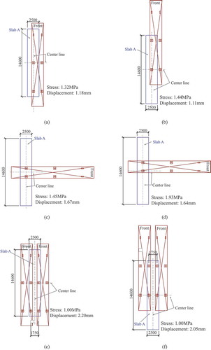
Figure 4. (Continued)
3. Calculation method of equivalent uniform live load in the Chinese Load Code
3.1. Chinese Load Code provisions
In Chinese Load Code, the equivalent uniform live load for the slab system can be determined according to Appendix C (GB50009-Citation2012, Citation2012). Since the slab systems in the transportation hubs are generally one-way slab systems, the equivalent uniform live load can be calculated according to the Chinese Load Code C0.4 and C0.5, which will be introduced in the following. When the driving direction of the BRTs is parallel to the one-way slab width and one tire group is placed at the center point, the structural response is the largest according to the results in . When only one tire group load is applied to the slab, and the long side of loading projection is perpendicular to the slab width (as shown in ), the effective distribution width should be calculated by using EquationEquation (1)(1)
(1) . In , bcx is the loading projection width and bcy is the loading projection length. However, an axle of BRT actually has two groups of tires and more than one BRTs are arranged together as shown in ). Therefore, the revised effective distribution width is usually calculated by using EquationEquation (2)
(2)
(2) when the spacing between tire groups are less than the effective distribution width calculated by EquationEquation (1)
(1)
(1) (as shown in ).
Figure 5. Effective distribution width under a tire load
Figure 6. Effective distribution width under adjacent local loads
The calculation procedures according to the Chinese Load Code are as follows:
The effective distribution width b of the tire load on the one-way slab is:
where l is the one-way slab span (width). When e is less than the effective distribution width b, the effective distribution width can be written as:
In order to calculate absolute maximum moment (Mmax), the one-way slab is simplified as a simply supported one-way slab and the long sides are the supports. The tire loads are applied to the simply supported one-way slab, and Mmax can be calculated through FE analysis. Thus, the equivalent uniform live load qe is:
where b is the effective distribution width of the slab and Mmax is absolute maximum bending moment of the simply supported one-way slab.
Four groups of 16 FE models are established to consider different aspect ratios. Each FE model group has the same aspect ratio, the dimensions of the FE models are shown in . The length of slab in the urban transportation hub usually more than 10 m, therefore, three buses can be placed on the slab at the most unfavorable positions to obtain the equivalent uniform live load and the corresponding structural response, as shown .
Figure 7. Tires arrangement at the most unfavorable loading position
3.2. Results of equivalent uniform live loads
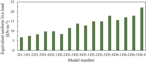
The effective distribution width, absolute maximum bending moment, and equivalent uniform live load of each slab can be obtained according to the previously mentioned equations. Two or more BRTs are arranged side by side, thus the effective distributed width (as shown in ) is only related to the spacing of groups of tires. For example, there are six groups of tires on the slab (). One group of tires is in the centerline of slab, and another group of tires in the same BRT is 1.8 m away from it, while the group of tires in another BRT is 1.75 m away from it. The effective distribution width is 1.775 m as shown in , and the effective distribution width of all FE models in is similarly a constant of which the value is 1.775 m. As shown in , the absolute maximum bending moment approximately increases with the increase of slab span, while the calculated equivalent uniform load decreases with the slab span increasing (as shown in ).
Figure 8. Absolute maximum bending moment calculated by the Chinese Load Code
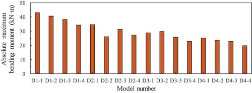
Figure 9. Equivalent uniform live load calculated by Chinese Load Code
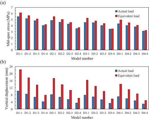
Both actual loads of the BRT tires and equivalent uniform live loads calculated by the Chinese Load Code are applied to the models listed in . The mid-span stress and the mid-span vertical displacement are obtained by FE analysis. The results from indicate that the mid-span stress under the actual loads decreases with the increase of the aspect ratio, and the mid-span stress under the equivalent uniform load increases with the increase of aspect ratio. The mid-span stress of the equivalent uniform load is less than that of the actual load, which means unsafe.
Figure 10. Comparison of structural response under actual load and equivalent uniform live load: (a) Mid-span stress, (b) Mid-span vertical displacement
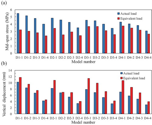
The mid-span vertical displacement under the actual tire load decreases slightly with the increase of the aspect ratio, and the mid-span vertical displacement of the slab under equivalent uniform live load is less related to the aspect ratio. The mid-span vertical displacement is greatly related to the slab length, but slightly related to the aspect ratio.
The main reasons for the results from are as follows: (1) the actual tire load is applied to small area around tire, but the structural responses under the actual tire load is extremely large. (2) According to EquationEquation (3)(3)
(3) , the effective distribution width leads to the decrease of the equivalent uniform live load. (3) The equivalent uniform live load increases with the aspect ratio increasing, resulting in an increase of mid-span stress. However, the structural responses under the actual load may decrease with the aspect ratio increasing because the loading diffusion effect gets bigger with the aspect ratio.
It can be concluded that structural responses under the equivalent uniform live load based on the current Chinese Load Code is lower than that under the actual load. This may result in an unsafe design of the slab system, and is not suitable for the slab design of urban transportation hubs.
4. Equivalent uniform live load with an aspect ratio
4.1. Revised equivalent uniform live load
EquationEquation (3)(3)
(3) reveals that the equivalent uniform live load calculated by the current Chinese Load Code is only related to the span of the one-way slab. To prove that the structural response under the BRTs’ tire load is related to the length of slab, four one-way slab models with the same width and different lengths are established, shown in . The same tire load is applied to the mid-span of the middle slab in the four models in .
Figure 11. Structural arrangement of different lengths of the one-way slab and the structural response under the tire load: (a) 18 m one-way slab, (b) 15 m one-way slab, (c) 12 m one-way slab, (d) 9 m one-way slab. (unit: mm)
The structural responses in reveal that the mid-span bottom stress decreases with the decrease of the length of the one-way slab. The current Chinese Load Code cannot effectively consider the effects of the one-way slab length, and it will lead to inaccurate results. Therefore, the revised equivalent uniform live load is proposed in this research. The detailed procedures of the revised calculation method are as follows:
The effective distribution width can be still determined based on the current provision in the Chinese Load Code.
As shown in , the selected strip under the local tire load can be equivalent to a simply supported beam. A local uniformly distributed live load is applied to the middle of the simply supported beam. The absolute maximum bending moment of the beam is:
where q is wheel distributed uniform load.
Figure 12. Calculation diagram of absolute maximum bending moment
Then, the relationship between the coefficient α (α = qebl/8Mmax) and the aspect ratio is investigated. b and Mmax are obtained in EquationEquation (1)(1)
(1) /(2) and EquationEquation (4)
(4)
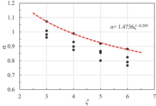
(4) , respectively. qe is determined by the actual situation according to the equivalent principle of structural response. shows a scatter plot of α and ξ (the aspect ratio). A proper curve is selected to model the relationship shown in the figure. The enveloping curve is mathematically expressed as:
where ξ is the aspect ratio of a one-way slab.
Thus, EquationEquation (3)(3)
(3) could be rewritten as:
where l is the span of the slab; b the effective distribution width of load on the slab, calculated by EquationEquation (1)(1)
(1) or EquationEquation (2)
(2)
(2) .
Figure 13. Fitting of α and the length-width ratio
4.2. Structural responses under revised equivalent uniform live loads
The structural responses under the revised equivalent uniform live load of the models in are calculated. The effective distribution width is still a constant of which the value is 1.775 m. Then, the absolute maximum bending moment and equivalent uniform live load are calculated by using EquationEquations (4)(4)
(4) , (Equation5
(5)
(5) ) and (Equation6
(6)
(6) ), respectively. The structural responses under the actual load and the revised equivalent uniform load are shown in .
Figure 14. Comparison of structural response under actual load and revised equivalent uniform live load: (a) Mid-span stress, (b) Mid-span vertical displacement
The discussions can be made on the results from as follows. (1) The mid-span slab stress of the revised equivalent uniform live load is in excellent agreement with the actual load, and the structural response decreases with the increase of aspect ratio. In addition, the stress under the revised equivalent uniform live load is slightly more than that under the actual load. (2) The mid-span vertical displacements caused by both actual load and revised equivalent uniform load decrease with the increase of aspect ratio.
The reasons for the results are as follows. (1) The revised calculation method of absolute maximum bending moment considers the features of the tire load. (2) The revised equivalent uniform live load considers the influence of the aspect ratio of the one-way slab system. Hence, the revised method developed in this research can accurately calculate the equivalent uniform live load for the one-way slab systems of the urban transportation hubs.
5. Verification of actual engineering
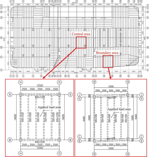
The revised equivalent uniform live load considering the aspect ratio has been proposed above. However, the aforementioned layout of structures in are relatively simple compared to a real urban transportation hub. Therefore, the structural response of a real urban transportation hub is calculated to verify the accuracy of the revised calculation method. A central area and a boundary area are chosen from the slab system of the real structure. The chosen areas are highlighted within the red-colored rectangles in .
Figure 15. Slabs in the central and boundary area (unit: mm)
The effective distribution width, the absolute maximum bending moment, the coefficient α and equivalent uniform live load of the urban transportation hub slabs are calculated by using EquationEquations (2)(2)
(2) , (Equation4
(4)
(4) ), (Equation5
(5)
(5) ) and (Equation6
(6)
(6) ), respectively. lists the results. Then, the revised equivalent uniform live load is applied to the slab system of a real urban transportation hub. The mid-span stress and vertical displacement under the revised equivalent uniform live load are compared with the structural responses under the actual load. The results of reveal that the structural responses under the revised equivalent uniform load with the aspect ratio are in good agreement with the structural responses under actual load. The revised equivalent uniform live load has no relationship with the location of the concerned slab areas.
Figure 16. Comparison of structural response under actual load and revised equivalent uniform live load in central and boundary area: (a) Mid-span slab stress, (b) Slab vertical displacement
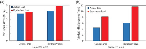
Table 2. Slab load parameters
As mentioned in section 2.2, the most of the urban transportation hubs in China used the one-way slab system. This paper aims to provide a revised equivalent uniform live load for the one-way slab system. It should be noted that for the two-way slab system, the equivalent uniform live load needs further investigation.
6. Conclusions
This paper presented a revised equivalent uniform live load considering the aspect ratio of one-way slab system for the urban transportation hubs. The main conclusions could be drawn as follows:
(1) The calculation method of equivalent uniform live load is simpler than the method of arranging specific load at the most unfavorable loading position, and is more accuracy than the method of arranging uniform load in the whole area. Therefore, the equivalent uniform load method is a useful and effective.
(2) The absolute maximum bending moment calculated by the current Chinese Load Code is not sufficient to reflect the force transmission characteristics of the small-area tire load on the one-way slab. The Chinese Load Code does not consider the effect of the one-way slab length, so the structural response under the equivalent uniform live load of Chinese Load Code is smaller than that under actual load.
(3) According to the force transmission characteristics of urban transportation hub slab, the revised equivalent uniform load is proposed considering the aspect ratio of the one-way slab system. The structural responses under the revised equivalent uniform live load are in good agreement with those under the actual load. The results also indicate that the revised equivalent uniform live load method can balance the structural safety and economic cost.
(4) The actual engineering verification shows that the revised calculation method can apply to the slab whether in the middle or edge of urban transportation hub. The revised equivalent uniform live load is suitable and efficient for the design of slab system in the urban transportation hub and similar structures.
Disclosure statement
No potential conflict of interest was reported by the authors.
Additional information
Funding
Notes on contributors
Yuhang Li
Yuhang Li is a Ph.D. student and his principal research interests include seismic and wind-resistant of civil engineering structures, etc.
Yang Deng
Yang Deng is a Professor and his principal research interests include structural health monitoring, etc.
Aiqun Li
Aiqun Li is a Professor and his principal research interests include seismic and wind-resistant and seismic isolation of civil engineering structures, new engineering structure system, structural health monitoring and safety assessment, etc.
Peng Sun
Peng Sun is an Assistant Professor and his principal research interests include structural health monitoring, etc.
References
- AASHTO. 2012. AASHTO LRFD Bridge Design Specifications. 6th ed. Washington, DC.
- Aixia, H. 2013. “Study on Development Pattern of Public Transportation in Fuzhou City.” Advanced Materials Research 734-737: 1621–1624. doi:10.4028/www.scientific.net/AMR.734-737.1621.
- ASCE/SEI 7-16. 2016. “Minimum Design Loads for Buildings and Other Structures”.
- Bin, C., C. Guodong, and Z. Jimin. 2017. “Study on Equivalent Uniform Live Load on Main Floor Beam for Fire Engines.” Building Structure 42 (24), in Chinese: 22–25.
- BS6399. 1996. “Loading for Buildings - Part1: Code Practice for Dead and Imposed Loads”.
- The Central People’s Government of the People’s Republic of China. 2013, January 5. “Central People’s Government’s Guidance on Urban Priority Development of Public Transportation [Government Notice]”. http://www.gov.cn/zhengce/content/2013-01/05/content_3346.htm
- Clifton, G. T., C. Mulley, and D. A. Hensher. 2014. “Bus Rapid Transit versus Heavy Rail in Suburban Sydney – Comparing Successive Iterations of a Proposed Heavy Rail Line Project to the Pre-existing BRT Network.” Research in Transportation Economics 48: 126–141. doi:10.1016/j.retrec.2014.09.010.
- Conroy, K., and G. Tumialan 2015. Structural Repair of a Concrete Parking Garage Structure Using ACI 562. Seventh Congress on Forensic Engineering: 20–29.
- Duvanovaa, I., T. Bubnova, and M. Romanovich. 2016. “Efficiency of Use Underground (Dike) Multilevel Parking in Conditions of Cramped Housing Development.” Procedia Engineering 165: 1794–1800. doi:10.1016/j.proeng.2016.11.924.
- EN 1991- 1-1. 2002. “Eurocode1: Actions on Structures – Part1-1: General Actions - Densities, Self-weight, Imposed Loads for Buildings”.
- GB50009-2012. 2012. “Load Code for the Design of Building Structures”. (in Chinese)
- Junyuan, Y., L. Deng, and H. Wei. 2017. “Evaluation of Existing Prestressed Concrete Bridges considering the Randomness of Live Load Distribution Factor Due to Random Vehicle Loading Position.” Advances in Structural Engineering 20 (5): 737–746. doi:10.1177/1369433216664350.
- Kamjoo, V., and C. D. Eamon. 2018. “Reliability-based Design Optimization of a Vehicular Live Load Model.” Engineering Structures 168: 799–808. doi:10.1016/j.engstruct.2018.05.033.
- Keyvani, L., and M. Sasani. 2015. “Analytical and Experimental Evaluation of Progressive Collapse Resistance of a Flat-Slab Posttensioned Parking Garage.” Journal of Structural Engineering 141 (11): 04015030. doi:10.1061/(ASCE)ST.1943-541X.0001279.
- Le Jianxin, W., Y. L. Yuwei, W. Pengliang, and C. Yin. 2018. “Analysis on Equivalent Uniformly Distributed Live Load Value for Pure Electric Bus Parking Building.” Building Structure 48 (17): 67–71+59. in Chinese.
- Nifu, Q., and K. Haitan. 2019. “Parametric Effects on Composite Floor Systems under Column Removal Scenario.” Engineering Structures 187: 161–176. doi:10.1016/j.engstruct.2019.01.139.
- Xin, W., H. Damin, L. Baozhong, and Z. Lebin. 2019. “Parametric Research on Equivalent Uniform Live Load of Beam-slab Floor Systems for Fire Engines.” Building Structure 49 (21): 69–72. in Chinese.
- Yang, B., Y. Yong, Z. Xu-Hong, J. Qiang-Fu, and K. Shao-Bo. 2018. “Component Tests and Numerical Simulations of Composite Floor Systems under Progressive Collapse.” Journal of Constructional Steel Research 151: 25–40. doi:10.1016/j.jcsr.2018.09.008.
- Zhong, F., J. Hongmei, and P. Zhonghua. 2011. “Study on Equivalent Uniform Live Load for Fire Engines.” Building Structure 41 (3): 1–6. in Chinese