
ABSTRACT
Recently, unmanned aerial vehicle (UAV)-based survey techniques have been applied to correct and update topographic maps for earthworks. It is essential to rectify the location values by arranging ground control points (GCPs) appropriately to improve the accuracy of UAV-based 3D topographic maps of earthwork sites. Despite the importance of the GCP arrangement, there is no effective standard for the appropriate placement of GCPs. The objective of this study was to propose an optimal arrangement of GCPs for an earthwork site using UAVs. The results showed that the error was minimized (dxyz value = 0.051 m) when there were six GCPs with a mean interval of 189.0 m at the target site (410 × 310 m). When an inside GCP was added, the dxyz value could be decreased to 0.043 m. Additionally, based on the results, this study proposed the establishment of GCP standards for realizing UAV-based precision digital maps of earthwork sites. When the GCP standards proposed in this study are used in the field, it will be possible to reduce the reliance on the capabilities of the surveyor. It will also be possible to secure the accuracy of digital maps above a certain level and even improve the measurement productivity.
1. Introduction
1.1. Background and purpose of the study
In South Korea, earthworks are the fourth-most common type of major construction work (10.8%) after reinforced concrete construction (20.0%), mechanical equipment construction (16.2%), and interior architecture construction (11.4%). In this large-scale construction industry, over 8 billion USD of contracts are signed annually (KOSCA Citation2018). Recently, earthwork sites have been scanned in 3D to provide baseline data for the automatic control and guidance of heavy equipment used for earthworks, such as excavators and bulldozers (Chae et al. Citation2011; Kim and Park Citation2015).
There are two methods used to obtain 3D images of earthwork sites: (1) field measurements using a light detection and ranging (LiDAR)-based 3D scanner or a mobile mapping system (MMS), and (2) unmanned aerial vehicle (UAV) photogrammetry. Of these, the UAV photogrammetry method has demonstrated superior flexibility and economic feasibility in system operations compared with other methods (Park and Kim Citation2019). Consequently, attempts have been made in recent years to utilize this method to correct and update earthwork topographic maps and establish cadastral boundaries (Lee and Sung Citation2018).
It is necessary to rectify the position value of the photogrammetry results generated by the UAV by appropriately arranging ground control points (GCP) on the earthwork site (Han Citation2019). However, despite the importance of the GCP arrangement, the Guideline for Public Survey Using Unmanned Aerial Vehicles (National Geographic Information Institute of Korea Citation2020) only states that more than nine GCPs should be arranged per km2 (with points at 500 m intervals), while no specific placement method is specified.
Therefore, the objective of this study was to propose an appropriate arrangement method for GCPs, which are essential for constructing precision digital maps of earthwork sites using UAVs. To achieve this objective, this study established hypotheses for analyzing the arrangement location, interval, and number of GCPs, and analyzed the accuracy of digital maps of the earthwork site based on the research hypotheses.
1.2. Scope and method of the study
The scope of this study was limited to analyzing the location accuracy of ground examination points presented on a digital map based on the arrangement, location, interval, and number of GCPs at the earthwork site using a UAV. The following methods were employed to achieve the study objective:
1) Previous studies and technology development trends related to the realization of precision digital maps using UAVs were analyzed. Furthermore, hypotheses were established for analyzing the arrangement, location, interval, and number of GCPs based on analysis of previous studies related to the arrangement and configuration of GCPs and interviews with experts.
2) Earthwork sites were selected for the realization of precision digital maps using a UAV, and precision digital maps of the earthwork site were created for each GCP arrangement method to test the established hypotheses.
3) The established hypotheses were tested by analyzing the location accuracy of the GCPs presented on the precision digital maps of earthwork sites in terms of their arrangement, and an appropriate arrangement method for GCPs was proposed to realize precision digital maps of earthwork sites using UAVs.
2. Preliminary experiment
2.1. UAV photogrammetry for topography
Earthwork refers to the construction of a structure using soil or its foundation (GB center Citation2010). Earthwork is conducted on a large scale, and its work environment is variable. Many studies have evaluated methods for improving the work efficiency by applying UAVs and digital information communication technology (Park et al. Citation2019).
Gonçalves and Henriques (Citation2015) and Andriolo et al. (Citation2020) demonstrated the effectiveness of monitoring changes in the terrain in coastal areas using UAVs. Moreover, Lamsters et al. (Citation2020) generated a digital surface model (DSM) and high-resolution orthoimages of the South Pole region using drones. Hugenholtz et al. (Citation2015) calculated the volume of a gravel pile at a civil engineering site by creating a digital topography model using drones and photogrammetry. Siebert and Teizer (Citation2014) conducted surveys by flying drones at a constant altitude over large-scale excavation and earthwork sites (60,000 m2) and derived higher accuracy topographic modeling results with the use of multiple GCPs. Moreover, Lim, Seo, and Yun (Citation2015) proposed a method that could quickly and accurately measure the volume of earthwork in a difficult-to-access dredged soil dump site using aerial photographs taken by an ultra-light drone; a precise digital elevation model (DEM) was created through image processing, and a cross-sectional view was extracted. Moon et al. (Citation2019) derived a more precise topographic map by simultaneously utilizing UAV and LiDAR equipment to establish a work plan for intelligent construction using heavy equipment for earthwork.
Furthermore, by analyzing the earthwork process, Moon and Moon (Citation2017) developed a system prototype that applied smart glass technology to provide the benefit of continuous communication between construction equipment operators. The system was established to allow managers and operators to access diverse information such as changes in work plans, progress, and waiting times through the smart glass screen of the system. In addition, Lim and Kim (Citation2017) developed an optimal operation system for construction equipment that provided the soil distribution at the construction site, movement routes of all equipment, and guided the work routes in real-time. This system could reduce the cost and improve the management efficiency of equipment by increasing the productivity of earthwork transportation through the use of global geographic information system (GIS) data.
2.2. Analysis of previous studies related to ground control point set-up
A GCP is a reference point that is installed based on supplementary surveys at certain intervals using triangulation or precision real-time kinematic/post-processed kinematic (RTK/PPK) surveying equipment on the ground to compensate for errors in measurement due to the high-speed movement of the aircraft body, unstable posture, and inaccuracy of the GPS sensors mounted on the aircraft during the aerial survey. This step is particularly important for UAV surveys because UAVs are affected by wind and equipped with relatively inexpensive GPS sensors (Lee, Hwang, and Choi Citation2018).
The Guideline for Public Survey Using Unmanned Aerial Vehicles in Korea (National Geographic Information Institute of Korea Citation2020) stipulates that it is necessary to install more than nine GCPs per km2 (one point per 500 m interval) and ground examination points should comprise at least 1/3 of the GCPs. However, the results of interviews with experts who have performed these surveys using drones in the field indicate that it would be difficult to create a topographic map satisfying the accuracy required by the field (approximately 5 cm) based on the current Korean standards. It was found that surveyors established GCPs based on their intuition and experience. These results imply that it will be necessary to present more effective criteria for setting GCPs.
In general, more GCPs correspond to a higher accuracy of the digital maps produced. However, minimizing this process is necessary to increase the cost- and operation-efficiency because the process of GCP installation is highly labor-intensive and requires a large amount of time and manpower. Pix4d, which currently leads the digital mapping market, analyzed the accuracy obtained with installation of 18 GCPs at the Nevada Department of Transportation quarry, a site that is approximately 610 × 300 m and has a 55 m difference in elevation. It was reported that accuracy the accuracy was improved, even if slightly, with the use of five or more GCPs (Pix4D Citation2018).
Uysal, Toprak, and Polat (Citation2015) aimed to examine the accuracy of UAV photogrammetry for production of a topographic DEM. They obtained a location accuracy of 0.066 m for ground examination points after applying 27 GCPs for an area of 250 × 250 m. Choi, You, and Cho (Citation2015) applied 18 GCPs for an area of 650 × 650 m and obtained location accuracies of σXY = 0.064 m and σZ = 0.034 m for the ground examination points. Remondino et al. (Citation2011) applied 27 GCPs for a 35 × 25 m excavation area and obtained location accuracies of σX = 0.04 m, σY = 0.03 m, and σZ = 0.07 m for the ground examination points. Additionally, Harwin and Lucieer (Citation2012) applied 27 GCPs for a 150 × 50 m waterfront area and obtained a location accuracy of 0.025–0.040 m for the ground examination points. As demonstrated by the above studies, an excessive number of GCP placements does not improve the location accuracy for generation of a precise digital map, but rather wastes time and expenses.
Although the utilization of RTK and PPK is increasing to save time and costs, it is still essential to use GCPs to more accurately determine exterior orientation parameters (Han Citation2019).
3. Hypotheses and experimental methods for analyzing the accuracy of digital maps based on the GCP arrangement method
3.1. Establishment of hypotheses for analyzing the accuracy of digital maps based on the GCP arrangement method
This study interviewed 13 experts with experience in creating earthwork digital maps using UAVs in the field regarding the installation of GCPs. These interviews revealed that there is no standard reference in the field for installing GCPs, and GCPs were typically installed based on the intuition or experience of the surveyor. As a result, the method of installing GCPs varies between surveyors and the derived accuracy also differs, which is problematic. This study established the following hypotheses for analyzing the accuracy of digital maps according to the GCP setup methods based on the interview results.
Do the points inside the polygon made by three or more GCPs and those outside the polygon have different accuracies?
H0: The accuracy of the inside points and that of the outside points is the same.
H1: The accuracy of the inside points and that of the outside points is different.
Does accuracy improve when the outskirt installation interval of GCPs is less than 500 m, the current standard in South Korea?
H0: There is no difference in accuracy even if the outskirt installation interval of GCPs is less than 500 m.
H1: Accuracy improves when the outskirt installation interval of GCPs is less than 500 m.
If a sufficient number of outskirt GCPs are installed on-site, is it meaningful to install additional inside GCPs?
H0: If there are sufficient outskirt GCPs at the site, the installation of additional inside GCPs does not affect the accuracy.
H1: Even if there are sufficient outskirt GCPs at the site, the installation of additional inside GCPs affects the accuracy.
This study established the experts’ opinions as hypotheses and conducted an investigation to verify them.
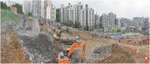
3.2. Target site overview
A condominium complex construction site of 410 × 310 m located in Dongjak-gu, Seoul, South Korea, was selected to analyze the accuracy of digital maps based on the GCP arrangement (). The site was undergoing earthwork during the study. Moreover, because excavation work was being performed simultaneously at the site, the topography changed frequently. Additionally, the difference in elevation within the site was up to 55 m, which can cause relatively large errors in digital maps created by UAV photography.
Figure 1. Overview of the target site selected to analyze the accuracy of digital maps
This study established 8 GCPs (1–8) at approximately 150 m intervals based on the boundary of the target site to analyze the accuracy of digital maps based on the arrangement of GCPs. Moreover, four ground examination points (A–D) with a difference in elevation were installed inside the target site ( and and ).
Figure 2. Arrangement of ground control points at the target site
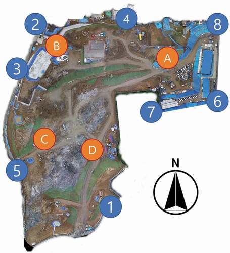
Figure 3. Ground control point installation at the target site
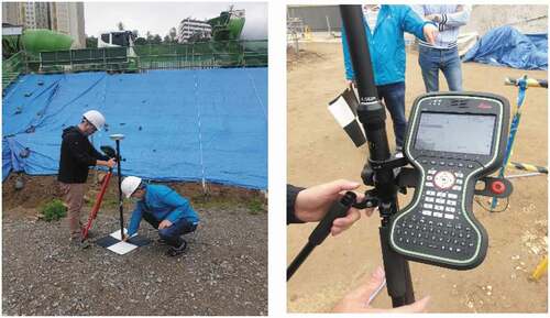
Table 1. Coordinates of ground control points at the target site
3.3. UAV image acquisition method for analyzing the accuracy of digital maps using GCPs
The DJI Co. Inspire 2 was used as the UAV to acquire image information at the site. A Zenmuse X5S (M 4/3, 5.2 K 30 fps, 20.8 MP) camera was used for image collection and a DJI MFT (15 mm/f1.7 ASPH) was used for the lens. This study used an 80% and 60% image overlap (frontal/side) ratio, commonly used in the field. Based on the obtained images, Pix4D Mapper Ver. 4.5.6 was used to generate point cloud data for the earthwork topography, and SERK-Mapper was used to analyze the accuracy of the ground examination points ( and ).
Figure 4. UAV-based flight plan and method
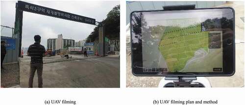
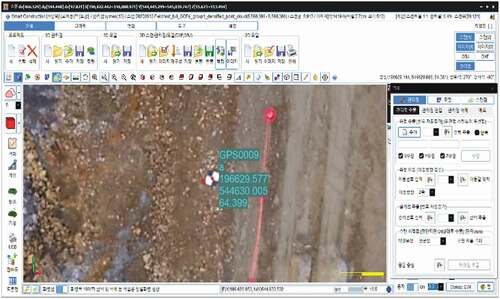
Figure 5. Accuracy analysis using SERK-Mapper
4. Digital map accuracy analysis based on the GCP arrangement method
4.1. Comparing and analyzing the accuracy of digital maps based on the location of ground examination points (points outside/inside the site)
This study generated five types of digital maps according to the number of GCPs (3–7 points). The accuracies were compared and analyzed by dividing the ground examination points into those inside and outside the site () to test the first null hypothesis (“The accuracy of the inside points and that of the outside points is the same”) established in Section 3.1.
Table 2. Accuracy of digital maps based on the location of ground examination points (outside/inside the site)
Analysis of the data for 35 ground examination points in five digital maps indicated that the accuracy of points inside the site was superior in all five models. The RMSE of the points inside the site was 0.129 m, whereas that of the points outside the site was 0.262 m, indicating that the inside points were at least twice as accurate as the outside points. In other words, the results suggest that the accuracy increases when the ground examination points are inside the polygon created by the GCPs.
4.2. Analyzing the accuracy of digital maps based on the interval of GCPs
The mean interval depending on the number of GCPs (3–7) installed outside of the site was calculated and the accuracies of the ground examination points were compared and analyzed based on the mean interval of GCPs to test the second null hypothesis (“There is no accuracy difference even if the outskirt installation interval of GCPs is less than 500 m”) established in Section 3.1. Because a ground plan is used to design the arrangement of GCPs, it is difficult to establish a plan considering the elevation of the ground. Therefore, the mean interval between GCPs is expressed as the distance on a plane. In this study, the accuracies of ground examination points (A–D) installed at the site were compared and analyzed based on the digital maps generated with varying intervals of GCPs outside the site ().
Table 3. Accuracy of digital maps based on the interval between ground control points
4.2.1. Plane location accuracy analysis based on the interval between GCPs
Analysis of the location accuracy based on the interval of the GCPs indicated that the dx value decreased drastically from 0.139 m to 0.055 m as the mean interval of GCPs decreased from 329.8 m (3 GCPs) to 278.3 m (4 GCPs). Moreover, the dx value was the lowest (0.035 m) when the mean interval was 147.0 m (8 GCPs). The dy value showed the highest location accuracy (0.004 m) when the mean interval was 189.0 m (6 GCPs). Finally, the dxy value was 0.173 m when the mean interval was 329.8 m, and it drastically decreased to 0.058 when the mean interval was 278.3 m. The highest location accuracy (0.041 m) was achieved when the mean interval was 189.0 m ().
Figure 6. Plane location accuracy based on the interval between ground control points
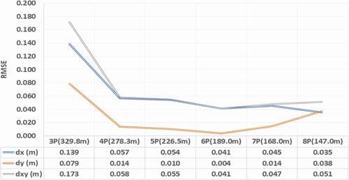
Overall, the location accuracy in the plane increased considerably when the mean interval was less than or equal to 278.3 m. Thereafter, the plane location accuracy did not improve significantly relative to the effort required to increase the number of GCPs.
4.2.2. Vertical location accuracy analysis
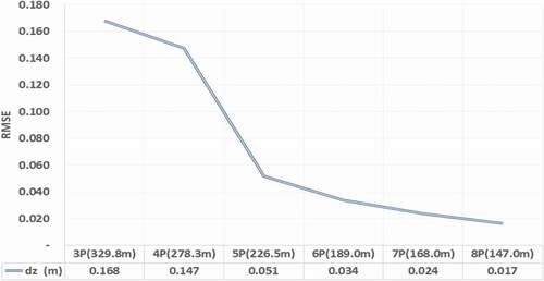
The results of the vertical location accuracy analysis based on the arrangement of GCPs revealed that the dz value decreased significantly when there were five or more GCPs and the mean interval was 226.5 m or less. It was found that the vertical location accuracy improved when the interval between GCPs was narrower ().
Figure 7. Vertical location accuracy based on the interval between ground control points
4.2.3. Comprehensive location accuracy analysis
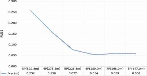
The comprehensive location accuracy was analyzed based on the interval between GCPs, and the results showed that the dxyz value had the highest location accuracy when there were six GCPs with a mean interval of 189.0 m. Increasing the number of GCPs did not significantly improve the accuracy. In other words, the most ideal GCP arrangement at the study site (410 × 310 m) was six GCPs at intervals of 189.0 m ().
Figure 8. Comprehensive location accuracy based on the interval between ground control points
4.3. Analysis of the digital map accuracy depending on the inclusion of GCPs inside the site
The accuracy of the digital map generated using eight outside GCPs was analyzed and compared with that generated using eight outside GCPs and one inside GCP to test null hypothesis 3 (“If there are sufficient outskirt GCPs at the site, the installation of additional inside GCPs does not affect the accuracy”) established in Section 3.1 ().
Table 4. Digital map accuracy analysis depending on the inclusion of an inside GCP
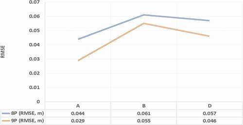
The results showed that the mean error of the digital map created using the eight outside GCPs was 0.054 m, whereas that of the digital map produced using eight outside GCPs and one inside GCP was 0.043 m. Moreover, as shown in , all three ground examination points (A, B, and D) showed a significant improvement in accuracy. Therefore, it was concluded that including inside GCPs could improve the accuracy of the generated digital maps.
Figure 9. Digital map accuracy depending on the inclusion of points inside of the site
4.4. Proposal for the establishment of GCP standards to realize precise digital maps of earthwork sites using UAVs
Chapter 2 Article 9 (Arrangement of Ground Control Points) of the Guideline for Public Survey Using Unmanned Aerial Vehicles (National Geographic Information Institute of Korea Citation2020) prescribes the establishment of GCPs as follows:
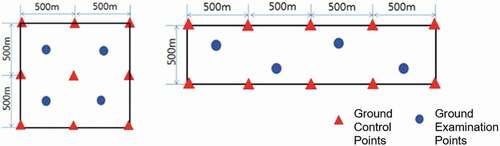
Moreover, Annex shows the arrangement method of the GCPs ().
Figure 10. Annex Table 1 in Chapter 2, Article 9 of National Geographic Information Institute Notice No. 2018–1075
This study proposes the following GCP establishment standards based on the results of testing the three hypotheses developed in Section 3.1. These proposed standards are intended to supplement Chapter 2 Article 9 of the Guideline for Public Survey Using Unmanned Aerial Vehicles (National Geographic Information Institute of Korea Citation2020), to produce UAV-based topographic maps with better precision and accuracy.
First, the target site should be located inside a polygon formed by GCPs to create a UAV-based precision digital map for an earthwork site.
Second, at least four GCPs should be placed at the outskirts of the site (based on a 350 × 350 m site) to secure the accuracy of the plane location for a UAV-based earthwork precision digital map. Moreover, it is necessary to have at least six GCPs at the outskirts of the site with intervals of less than 200 m to ensure high comprehensive location accuracy.
Third, a 350 × 350 m site must have at least one GCP inside the site to guarantee a high accuracy of the UAV-based precision digital map of the earthwork site.
5. Conclusions
The following conclusions were obtained through this study:
1) Previous studies related to the realization of UAV-based precision digital maps for earthwork sites were analyzed. The results showed that many studies have been conducted utilizing UAVs because they provide superior flexibility and economic feasibility for system operations compared with other methods. Previous studies related to GCPs were also reviewed, and an insufficient number of studies related to the establishment of GCPs was found. In many studies, the establishment of excessive GCPs did not improve the accuracy of digital maps, and it was clear that excessive GCPs can result in wasted time and money in the production of precision digital maps.
2) Five types of digital maps with varying numbers of GCPs were created in this study, and the accuracy of the maps was compared by dividing the locations of ground examination points into inside and outside points. The RMSE of the ground examination points was 0.129 m for the inside points and 0.262 m for the outside points, indicating that the inside points were at least twice as accurate.
3) This study analyzed the accuracy of digital maps using the arrangement intervals of GCPs. The results revealed that when the mean interval of the GCPs was reduced from 329.8 m to 278.3 m, dxy drastically decreased from 0.173 m to 0.058 m. When the mean interval of GCPs was 189.0 m, dxy reached the minimum value (0.041 m). In terms of the dy value, the vertical location accuracy increased when the interval between GCPs decreased. In terms of dxyz, the highest accuracy (0.054 m) was obtained when the mean interval between GCPs was 189.0 m.
4) In this study, the accuracy of digital maps was analyzed depending on the inclusion of GCPs inside the site. The results showed that the mean error of the digital map created using eight outside GCPs was 0.054 m, while that of the digital map produced using eight outside GCPs and one inside GCP was 0.043 m. In other words, the results revealed that including an inside point as a GCP could increase the accuracy of the digital map.
When the GCP establishment standards proposed in this study are used in the field, it will be possible to reduce the reliance on the capabilities of the surveyor when creating UAV-based digital maps for earthwork sites. It will also be possible to secure the accuracy of digital maps above a certain level and even improve the measurement productivity.
The conventional method directly checks the current status of the earthwork site or the design schedule. However, by using the UAV method of this study, it will be possible to check the situation of the earthwork site on a digital map based on images. In addition, construction management using real-time topographic information for sites such as earthworks and road works will be possible. Finally, it is expected that construction management will be possible for the entire life cycle, including not only the construction stage but also the maintenance of construction facilities.
This study has a limitation of analyzing the GCP arrangement method for only one target site. In addition, an analysis based on the site characteristics could not be performed, and the target site was limited to earthwork for apartment homes. In future studies, the results of applying the hypotheses and limitations of this study should be derived for a number of sites. In addition, these results should be applied not only to apartment earthwork sites but also to road and pavement construction to verify the hypotheses and restrictions of this study at those sites.
Disclosure statement
No potential conflict of interest was reported by the authors.
Additional information
Funding
Notes on contributors
Jae Woo Park
Jae Woo Park earned his master in Construction Management in 2002 from the Department of Civil Engineering, Chung-Ang University. He worked for the Korea Institute of Civil Engineering and Building Technology for 19 years and performed various research projects on sensor and sensor network, construction information technology, automation, and robotics in the construction area funded by the Korean government and major construction and equipment companies. He currently serves as a senior researcher in the Department of construction policy research since 2002. His research interests are in the areas of productivity improvement, sensor-based monitoring system, point cloud-based digital map in construction, and various applications of information technologies and automation in construction.
Dong Jun Yeom
Dong Jun Yeom earned his Ph.D. in Construction Management in 2018 from the Department of Architectural Engineering, Inha University. He worked for the Industrial Science and Technology Research Institute at Inha University for two years. He has given a series of lectures on computer-aided design, computer programming for engineering applications, and construction information technologies at Inha University since 2015. He currently serves as a postdoctoral research engineer at the Korea Institute of Civil Engineering and Building Technology.
References
- Andriolo, U., G. Gonçalves, F. Bessa, and P. Sobral. 2020. “Mapping Marine Litter on Coastal Dunes with Unmanned Aerial Systems: A Showcase on the Atlantic Coast.” Science of the Total Environment 736: 139632. doi:https://doi.org/10.1016/j.scitotenv.2020.139632.
- Chae, M. J., G. W. Lee, J. Y. Kim, J. W. Park, and M. Y. Cho. 2011. “A 3D Surface Modeling System for Intelligent Excavation System.” Automation in Construction 20 (7): 808–817. doi:https://doi.org/10.1016/j.autcon.2011.02.003.
- Choi, Y. W., J. H. You, and G. S. Cho. 2015. “Accuracy Analysis of UAV Data Processing Using DPW.” Journal of the Korean Society for Geospatial Information Science 23 (4): 3–10. doi:https://doi.org/10.7319/kogsis.2015.23.4.003.
- GB center. 2010. Heavy Equipment Engineering Golden Bell, Korea.
- Gonçalves, J. A., and R. Henriques. 2015. “UAV Photogrammetry for Topographic Monitoring of Coastal Areas.” ISPRS Journal of Photogrammetry and Remote Sensing 104: 101–111. doi:https://doi.org/10.1016/j.isprsjprs.2015.02.009.
- Han, S. H. 2019. “Project Design Plan for Drone Photogrammetry.” Journal of the Korean Society of Civil Engineers 39 (1): 239–246.
- Harwin, S., and A. Lucieer. 2012. “Assessing the Accuracy of Georeferenced Point Clouds Produced via Multi-View Stereopsis from Unmanned Aerial Vehicle (UAV) Imagery.” Remote Sensing 4 (6): 1573–1599. doi:https://doi.org/10.3390/rs4061573.
- Hugenholtz, C. H., J. Walker, O. Brown, and S. Myshak. 2015. “Earthwork Volumetrics with an Unmanned Aerial Vehicle and Softcopy Photogrammetry.” Journal of Surveying Engineering 141 (1): 06014003. doi:https://doi.org/10.1061/(ASCE)SU.1943-5428.0000138.
- Kim, S., and J. W. Park. 2015. “Analysis of Accuracy and Productivity of Terrestrial Laser Scanner for Earthwork.” The Journal of the Korea Contents Association 15 (10): 587–596. doi:https://doi.org/10.5392/JKCA.2015.15.10.587.
- Korea Specialty Contractors Association (KOSCA). 2018. “Contract Performance of Industrial Classification.” In Statistical Yearbook 2019. Republic of Korea: Korea Specialty Contractors Association.
- Lamsters, K., J. Karuss, M. Krievans, and J. Jeskins. 2020. “High-resolution Orthophoto Map and Digital Surface Models of the Largest Argentine Islands (The Antarctic) from Unmanned Aerial Vehicle Photogrammetry.” Journal of Maps 16 (2): 335–347. doi:https://doi.org/10.1080/17445647.2020.1748130.
- Lee, J. O., and S. M. Sung. 2018. “Assessment of Positioning Accuracy of UAV Photogrammetry Based on RTK-GPS.” Journal of the Korea Academia-Industrial Cooperation Society 19 (4): 63–68.
- Lee, J. W., D. W. Hwang, and J. H. Choi. 2018. “The Overview and Application of Measurement Using Drones.” Technical Newsletter of Yooshin Engineering Corporation 2: 237–256.
- Lim, S. B., C. W. Seo, and H. C. Yun. 2015. “Earthwork Management for Dredged Soil Dumping Area by Using Drone.” In Proceedings of the Conference on Korean Society of Civil Engineers, KSCE, 99–100. Republic of Korea.
- Lim, S. Y., and S. K. Kim. 2017. “A Study on the Real-time Earthwork with Optimal Operation System of Construction Equipment.” In Proceedings of the Conference on Korean Society of Civil Engineers, KSCE, 1253–1254. Republic of Korea.
- Moon, D., S. Chung, S. Kwon, J. Seo, and J. Shin. 2019. “Comparison and Utilization of Point Cloud Generated from Photogrammetry and Laser Scanning: 3D World Model for Smart Heavy Equipment Planning.” Automation in Construction 98: 322–331. doi:https://doi.org/10.1016/j.autcon.2018.07.020.
- Moon, S. W., and C. G. Moon. 2017. “Utilization of a Smart Glass for Improving Data Interface during the Earthwork Operation.” Journal of the Korean Society of Civil Engineers 37 (1): 167–174. doi:https://doi.org/10.12652/Ksce.2017.37.1.0167.
- National Geographic Information Institute of Korea. 2020. Public Survey Work Instructions Using Unmanned Aerial Vehicles in Notification No. 2018-1075.
- Park, J. W., and S. Kim. 2019. “MMS Accuracy Analysis for Earthwork Site Application.” Journal of the Korean Society of Industry Convergence 22 (2): 183–189.
- Park, J. W., W. G. Yun, S. S. Kim, and J. H. Song. 2019. “A Study on 3D Geospatial Information Model Based Influence Factor Management Application in Earthwork Plan.” The Korean Society of Industry Convergence 22 (2): 125–135.
- Pix4D. 2018. “DomoreGCPsequalmoreaccuratedronemaps? Pix4D Usecase.” https://www.pix4d.com/blog/GCP-accuracy-drone-maps
- Remondino, F., L. Barazzetti, F. Nex, M. Scaioni, and D. Sarazzi. 2011. “UAV Photogrammetry for Mapping and 3D Modeling –current Status and Future Perspectives.” International Archives of the Photogrammetry, Remote Sensing and Spatial Information Sciences, Vol. 38, ISPRS ICWG I/V.
- Siebert, S., and J. Teizer. 2014. “Mobile 3D Mapping for Surveying Earthwork Projects Using an Unmanned Aerial Vehicle (UAV) System.” Automation in Construction 41: 1–14. doi:https://doi.org/10.1016/j.autcon.2014.01.004.
- Uysal, M., A. S. Toprak, and N. Polat. 2015. “DEM Generation with UAV Photogrammetry and Accuracy Analysis in Sahitler Hill.” Measurement 73: 539–543. doi:https://doi.org/10.1016/j.measurement.2015.06.010.