
 ?Mathematical formulae have been encoded as MathML and are displayed in this HTML version using MathJax in order to improve their display. Uncheck the box to turn MathJax off. This feature requires Javascript. Click on a formula to zoom.
ABSTRACT
The durability and lifespan of concrete structures are significantly affected by the corrosion of steel reinforcement. Though epoxy-coated steel reinforcement is being used for practical applications, slight damage in the coating during the construction process is enough to initiate the corrosion process. The shortcomings in the current practices to prevent corrosion of steel reinforcement have led the researchers to look for alternatives. Innovative hybrid reinforcing elements with solid steel core and fibre-reinforced polymer (FRP) wrapping (called steel–FRP composite bars (SFCB)) can be considered as a suitable alternative to conventional steel reinforcement. In this research paper, experimental and numerical studies that investigated the flexural behaviour of concrete beam specimens reinforced with SFCB produced using glass fibres or carbon fibres are presented and discussed. Experimental study consisted of flexural testing of six concrete beam specimens with conventional steel reinforcement or SFCB with glass fibres or SFCB with carbon fibres. Two different spacings of shear stirrups were considered. Failure mode, first crack load, ultimate flexural load and load-deflection behaviour were recorded during the experiment. The test results showed that beam specimens with SFCB reinforced achieved less ultimate flexural load as compared to beam specimens with conventional steel reinforcement. The failure mode was found to be influenced by the spacing of the shear stirrups. The results of the numerical analysis were close to the experimental results. .
1. Introduction
Reinforced concrete (RC) is inevitable in the construction of civil infrastructure facilities such as bridges and buildings. The durability of RC structures is significantly affected due to corrosion of steel reinforcement, and this reduces their life span. It has been reported that the United States spends around 276 USD billion (3.1% of GDP) annually as a direct cost to corrosion (CitationURL-1). In order to curb the cost incurred due to corrosion in the future, new innovative reinforcing elements such as fibre-reinforced polymer (FRP), plasma rebars, corrosion-resistant rebars (steel rebars with higher content of chromium) and epoxy-coated rebars are being adopted for practical applications.
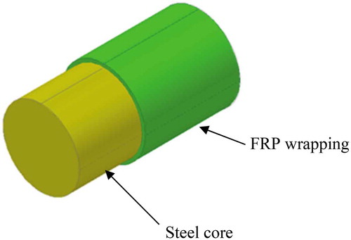
research studies (Toutanji and Saafi (Citation2000), Toutanji and Young (Citation2003), Masmoudi, Theriault, and Benmokrane (Citation2001)) have been conducted that investigated the influence of using FRP bars as reinforcement on the flexural behaviour of concrete beams. However, the use of FRP rebars for practical applications is limited primarily due to lower elastic modulus, brittle nature and high cost. In order to reduce the cost and achieve durable and ductile RC structures, researchers have proposed using combined steel and FRP bars as reinforcement (called hybrid reinforcement) in concrete members (Xu et al. (Citation2019), Sun et al. (Citation2019)). This type of reinforcement would reduce the cost of construction as compared to that incurred by using only FRP bars. While using hybrid reinforcement, FRP bars are placed near the outer surface of the concrete members (with lesser cover thickness) and steel bars are placed at inner areas (with higher cover thickness) thereby prolonging the time of initiation of corrosion and enhancing the lifespan of the structures. It is to be noted that, even though adopting hybrid reinforcement would increase the concrete cover for tension steel, steel stirrups that would have lesser cover would be used. Steel stirrups would therefore provide an electrical contact of the inner steel bars, and there are possibilities that the envisaged lifespan of the RC members might not be achieved. Towards improving the possibilities of combined use of steel bars and FRP bars for reinforcing concrete members, attempts have been made as early as the 1980s for developing rebars consisting of steel core and FRP wrapping around the core (herein called as steel-FRP composite bars (SFCB)). A typical photograph of SFCB is shown in . The FRP shielding would prevent or significantly reduce corrosion of steel core, thereby improving the lifespan of RC structures reinforced with SFCB and subjected to corrosive environment, especially in coastal regions.
Figure 1. Typical SFCB
Zhou et al. (Citation2019) have conducted experiments for studying the corrosion behaviour of SFCB using X-ray microcomputed tomography. Test results have showed that the type of fibre, micropore structure of the fibre coating layer and manufacturing process arethe factors that influenced the corrosion resistance of the rebars. The corrosion rate of SFCB was found to be significantly less than that of bare steel rebars. The authors have also found through tensile tests that the elastic modulus of the SFCB was more than that of GFRP and the tensile strength was more than that of steel rebars. Zhao et al. (Citation2020) have conducted experimental studies to determine the tensile properties of SFCB and their bonding performance in concrete. Test results have showed that SFCB with round steel core and FRP wrapping showed better tensile behaviour as compared to those with ribbed steel core and FRP wrapping. The authors have observed that the rule of mixtures can be used to describe the tensile behaviour of SFCB. The stress–strain curve of SFCB showed a bilinear trend. Bond strength of SFCB was influenced by the diameter and the surface treatment.
Fibre-reinforced concrete consisting of steel or synthetic fibres is reported to enhance the ductility of concrete, and it has also been shown that the addition of fibres improves the resistance of concrete to formation and propagation of cracks (Zhao et al. (Citation2016), Yehia et al. (Citation2016), Aldabagh, Abed, and Yehia (Citation2016), Farrag and Yehia (Citation2015), Yehia et al. (Citation2015), Yehia (Citation2012)).
In the literature, experimental research studies that determined the behaviour of concrete structural elements with SFCB are reported. However, experimental and numerical studies that investigated the flexural behaviour of fibre-reinforced concrete beams consisting of SFCB are not found to be reported. Numerical studies reported in the literature consisted of simulating the flexural behaviour of concrete beams with FRP bars as reinforcing elements or hybrid steel and FRP bars as reinforcing elements. Abed et al. (Citation2020) have carried out numerical simulations on the behaviour of concrete elements reinforced with FRP bars under different loading conditions. The authors have observed that the predicted behaviour of the elements compared well with the experimental results. Hawileh (Citation2014) conducted finite element studies to predict the load vs deflection behaviour of concrete beams reinforced with hybrid steel and FRP bars produced with aramid fibers. The authors observed that the load vs deflection behaviour could be predicted well using the model developed. The author also remarked that only limited numerical studies that investigated the behaviour of FRP-reinforced concrete elements are available in the literature. Bencardino, Condello, and Ombres (Citation2016) have carried out numerical studies on the behaviour of concrete beams with steel, FRP and hybrid FRP–steel reinforcements. The authors have observed that the tension stiffening model they have considered predicted the behaviour well for beams with low and normal reinforcement ratio; however, for beams with higher reinforcement ratio, the numerical predictions were not comparable to the test results. Similar numerical studies can be found elsewhere in the literature (Al-Rahmani and Abed (Citation2013), D D, Pisano, and Fuschi (Citation2014), Ferreira et al. (Citation2001), Rafi, Nadjai, and Ali (Citation2008), Nour et al. (Citation2007)). To the authors' knowledge, numerical simulation studies that predicted the flexural behaviour of concrete beams consisting of SFCB as reinforcing elements are not available in the literature.
The combined use of SFCB and steel fibres as reinforcement can be considered to be a novel technique for achieving higher durability and improved cracking resistance in concrete structural members. For developing design guidelines for practical applications, flexural behavior of concrete beams reinforced with SFCB and fibres has to be investigated experimentally and numerically, and that motivated the research presented in this paper.
In order to fill these gaps in the literature, in this paper, experimental studies are conducted to investigate the flexural behaviour of fibre-reinforced concrete beam specimens consisting of SFCB as tensile reinforcement. Two types of SFCB produced with glass fibers and carbon fibres are considered. The flexural behaviour of concrete beam specimens with SFCB is compared with control concrete beam specimens reinforced with conventional steel bars. The beam specimens are tested under 4-point bending with simply supported boundary conditions. Numerical analyses consisted of developing models of the tested beam specimens in general-purpose finite-element software ABAQUS and validating with test results.
2. Accelerated corrosion test
A pilot experimental study (Accelerated corrosion test) was conducted to determine the corrosion behaviour (gravimetric weight loss) of the proposed SFCB and compare it with that of conventional steel bars. It is known that corrosion of steel is an electrochemical process, and it involves anode, cathode and an electrolytic solution. The process of corrosion is shown in . (CitationURL-2).
Figure 2. Corrosion process (CitationURL-2)
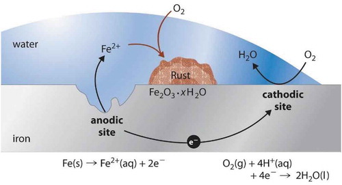
The corroding portion of steel is the anode and the un-corroded portion is the cathode. Electrolyte solution provides electrical contact between the anode and the cathode. Under favourable conditions, ferrous ions from anode (steel) enter into the electrolyte. The electrons that are released from the corroding part of the steel (anode) move towards the cathode and form hydroxyl ions by combining them with water and oxygen. These hydroxyl ions react with the ferrous ions that are released from the anodic portion of steel and form hydrated ferrous oxide. The ferrous oxide further gets oxidized to form ferric oxide which is known as the “red dust”.
Three bare specimens such as (i) steel, (ii) SFCB with glass fibers and (iii) SFCB with carbon fibers were considered for accelerated corrosion test. The SFCB were manufactured manually. Details of the manufacturing procedure of SFCB are available in the literature (Sivaraman and Chinnaraju Citation2019).
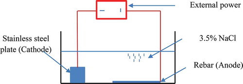
The acceleration of the corrosion process was achieved by impressing an anodic potential between the rebar anode and steel plate (Saraswathy and Song (Citation2008), Güneyisi, Özturan, and Gesolu (Citation2006), Song et al. (Citation2009)). The rebars were immersed in a 3.5% sodium chloride (NaCl) solution during the test. An impressed voltage of 10 V was applied to accelerate the corrosion process. The accelerated corrosion process was carried out for 24 h. The schematic diagram of the accelerated corrosion test setup is shown in .
Figure 3. Schematic diagram of accelerated corrosion test setup
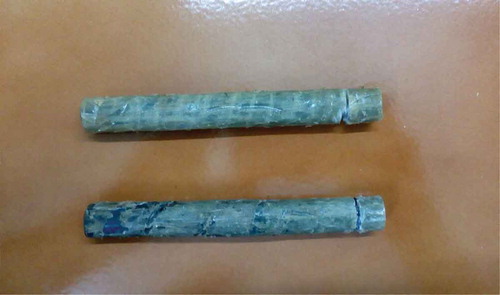
The SFCB specimens for the corrosion tests are shown in .
Figure 4. Rebars for accelerated corrosion test
The weight of steel and SFCB specimens was determined before the corrosion test and after the corrosion test and listed in . shows the steel and SFCB specimens after the accelerated corrosion test.
Figure 5. Rebars after accelerated corrosion test
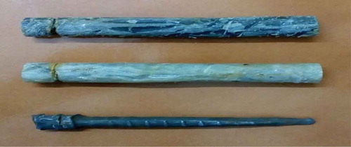
Table 1. Corrosion test results
It was observed from the test results that the conventional bare steel rebar lost most of its material due to corrosion. However, SFCB rebars with glass fibers or carbon fibers were found to be less affected. It was observed that the percentage loss of conventional steel rebar was very high as compared to the percentage loss of steel in SFCB with glass or carbon fibers. The corrosion test results showed that the durability of concrete structures could be improved enormously by using SFCB as reinforcing elements. It was noted that the accelerated corrosion tests were conducted on bare steel bars and SFCB. However, in practical applications, the steel reinforcement would be embedded in concrete. Further research studies on the corrosion behaviour of SFCB embedded in concrete are required to determine their actual corrosion behaviour.
3. Details of beam specimens and flexure test setup
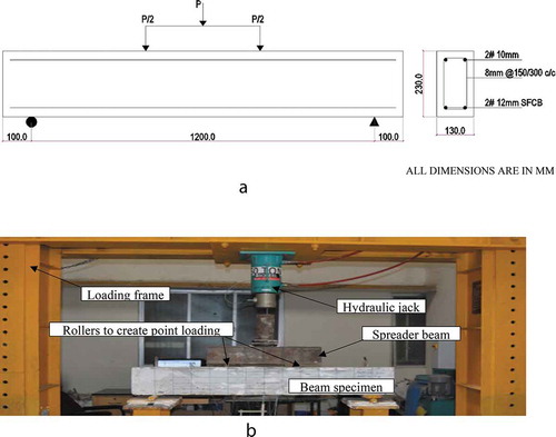
The experimental program consisted of testing six concrete beam specimens of dimension 130x230x1400mm (bxdxl) and reinforced with conventional steel rebars or SFCB with glass fibers (GFRP wrapping) or SFCB with carbon fibers (CFRP wrapping) in the tensile zone. In SFCB, GFRP or CFRP wrapping was provided over the entire length of the steel core. The diameter of the conventional steel rebars was 10 mm, and the diameter of SFCB produced by wrapping GFRP or CFRP for a thickness of 1 mm over the steel core of 10 mm diameter was 12 mm. Fe500 grade steel rebars were used. The hanger bars consisted of 2#10 mm diameter steel rebars, and stirrups were made of 8 mm steel rebars spaced at 150 mm c/c or 300 mm c/c. The effective cover for the tensile reinforcement was kept as 30 mm. Fibre-reinforced concrete with an average 28-day compressive strength of 26.3 was used for casting the specimens. The mix proportion of the concrete mix used was 1:1.51:2.77:0.45 in the order of cement (Portland Pozzolana Cement), fine aggregates (river sand) and coarse aggregates (20 mm gravel). Water–cement ratio of 0.5 was considered. Hooked type steel fibres with an aspect ratio of 60 were used in the concrete mix. The amount of fibres considered was 2% of cement content. The details of the beam specimens tested are given in .
Table 2. Beam specimen details
In , the effective reinforcement ratios are determined using the equation given below,
where ρs = As/bho, ρf = Af/bho, As is area of steel bars, Af is the area of FRP bars, b is section width, ho is section effective depth, fy is yield strength of steel, σcg or σcc is tensile strength of FRP using glass or carbon fiber. The corresponding balanced reinforcement ratio can be calculated as the ratio where concrete crushing and steel yield occur simultaneously given by ACI 440–1 R-06.
where ffu is tensile strength of FRP, εcu is ultimate strain in concrete, εfu is rupture strain of FRP bars, Ef is modulus of elasticity of FRP bars, β1 is the strength reduction factor taken as 0.85 for concrete strength up to 27.6 Mpa. This factor can be reduced if the strength is in excess of 27.6 Mpa, but it should not be taken less than 0.65.
The beams were subjected to 4-point bending. The beams were simply supported at both edges with a clear span of 1200 mm. The loading was applied using a 300 kN hydraulic jack and the load was transferred using a rigid transfer beam to form two point loads on the beam specimens. The distance between one of the loading points and the nearest support was 400 mm, and the shear span-to-depth ratio was kept as 1.95. A schematic diagram of the beam specimen with reinforcement details is shown in ) and a typical photograph of the test setup used is shown in ).
Figure 6. (a) Schematic diagram of specimen details. (b) Typical beam specimen in test setup
4. Details of numerical model
The FE model was validated first with beam specimens with conventional steel reinforcement () and only then used for modelling beam specimens with SFCB. Numerical models were developed for all the tested beams consisting of shear stirrups at a spacing of 150 mm in the finite element software ABAQUS. Concrete and reinforcement (steel and SFCB) were modelled as 3D parts using C3D8Relements. SFCB was modelled with a steel core of diameter 10 mm and GFRP/CFRP wrapping over the steel core for a thickness of 1 mm. The bond between the steel core and the GFRP/CFRP wrapping was assumed to be perfect, and it was achieved by using Tie constraint. Test results indicated that the tested beam specimens with SFCB as tensile reinforcement achieved lesser ultimate flexural load as compared to the beams specimens with conventional steel reinforcement. The reason for this observation was attributed due to the lesser bonding action between the SFCB and the surrounding concrete due to the smoother surface of the SFCB reinforcement (see Section 4.3). This behaviour was simulated in the model by specifying interaction property at the SFCB–concrete interface. Guo et al. (Citation2020) have observed that the friction coefficient at the steel–concrete interface could vary in the range 0.377–0.458. In this numerical model developed, the steel–concrete friction coefficient at the interface was kept as 0.3 for conventional steel reinforcement. For the beam specimens with SFCB, the friction coefficient of the SFCB–concrete interface was adjusted so as to get load–deflection curves comparable to that of test results. Iterations were made to get numerical load–deflection curves close to experimental load–deflection curves. Based on iteration, a friction coefficient of 0.1 was finalized as it resulted in numerical load–deflection curves close to experimental load–deflection curves.
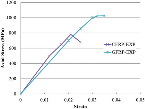
Unidirectional tensile test specimen was prepared according to ASTM D3916. UTM was used for the tensile test. The loading rate was 5 mm/min. After the rods are cured, additional epoxy resin impregnated glass fabrics were wrapped around the ends to increase their end diameter at least 1 mm to serve as tabs for gripping in a tensile testing machine. The rods are approximately 10 mm in diameter and 600 mm in length. The hybrid rebars using glass fibers consist of 30 numbers of glass fiber strands and hybrid rebars using carbon fibers consist of 14 numbers of carbon fiber strands. shows the tensile specimen and unidirectional test set up. shows the stress–strain graph of the hybrid rebars.
Figure 7. Tensile specimen and Unidirectional test setup
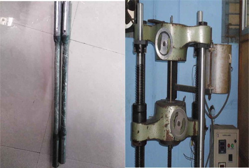
Figure 8. Stress–strain behaviour of hybrid rebars
The material property of steel was assumed to be bi-linear. An earlier study by Zhao et al. (Citation2020) indicated that the tensile strength of FRP based on the rule of mixtures was compared well with the experimental results.
In the present study, the yield strength of steel is 510 Mpa and the ultimate tensile strength of steel is 640 Mpa; tensile strength of GFRP and CFRP wrapping was obtained based on the rule of mixtures, and it was 1157MPa and 882MPa, respectively (Sivaraman and Chinnaraju Citation2019). The elastic modulus of GFRP and CFRP wrapping was also obtained based on the rule of mixtures and were found to be 37,920 MPa and 41,400 MPa, respectively (Sivaraman and Chinnaraju Citation2019).
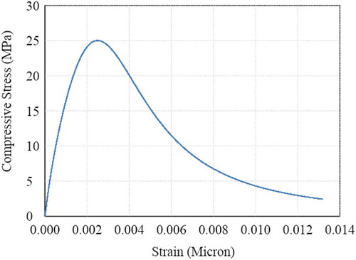
The constitutive relationship for concrete was modelled using Concrete Damaged Plasticity option available in ABAQUS. The uni-axial stress–strain curve of concrete in compression was modelled using the equation proposed by Saenz (Citation1964) and is shown in .
Figure 9. Stress–strain curve for concrete under Uni-axial compression
The behaviour of concrete under tension was modelled using the fracture energy criterion. The fracture energy of the concrete was calculated using Fib Model Code (Citation2010) equation as given below.
Fracture lab energy
The tensile strength of concrete was determined using the formula suggested by Graham and Scanlon (Citation1986) as given below.
Tensile strength,
The elastic modulus of concrete was arrived based on IS 456:Citation2000.
Elastic modulus,
where fck is the characteristic compressive strength and fcm is the mean compressive strength of concrete.
5. Test results and discussion
5.1. Failure mode
The photograph of the tested beam specimens is shown in .
It is observed from that the cracking pattern of the tested beam specimens was influenced by the type of reinforcement used and the spacing of shear stirrups. More number of flexural cracks occurred in the beam specimens BS150 and BS300 (as compared to other beam specimens tested), and the final failure was due to the opening of one flexural crack formed near the mid-span. The number of cracks in the beam specimen BS150 was more than that formed in the beam specimen BS300. It was also observed that, at failure, in beam specimen BS150, crushing of concrete in the compression zone occurred in the mid-span. The beam specimens BS150 and BS300 failed in flexural mode.
In the beam specimens HBG150 and HBG300, the number of cracks formed at failure was significantly influenced by the spacing of the shear stirrups. The number of cracks in the beam specimen HBG150 was more than that in the beam specimen HBG300. The beam specimen HBG150 failed by the widening of the crack formed in the shear span region. The crack was initially oriented vertically such that it occurred primarily due to flexural stress; however, it became inclined with an increased magnitude of applied flexural loading. The crack tended to join one of the loading points and the bottom edge of a cross-section that was located slightly away from the nearest support.
Figure 10. Tested beam specimens
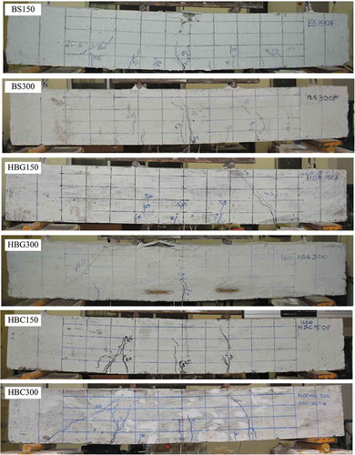
The beam specimen HBG300 failed due to an inclined shear crack that tended to join one of the loading points and the nearest support. At failure, the concrete in the compression zone of the beam specimen HBG300 also failed due to crushing. It is worth to note the difference in the observed failure modes of the beam specimens HBG150 and HBG300. The difference was that the inclined shear crack tended to join one of the loading points and bottom edge of the cross-section that was located slightly away from the support in the beam specimen HBG150 (called flexure–shear interaction failure mode); however, the inclined shear crack tended to join one of the loading points and the support in the beam specimen HBG300 (called as shear failure mode). The failure mode of the beam specimen HBG300 was exactly similar to the failure of deep beams. These observations clearly indicated that the spacing of shear stirrups influenced the failure mode of the beams reinforced using SFCB produced using glass fibre wrapping.
Except for the crushing failure of concrete in the compression zone in HBG300, the failure modes of the beam specimens HBC150 and HBC300 were similar to that of the beam specimens HBG150 and HBG300, respectively.
5.2. First crack load
The first crack load of the tested beam specimens is given in .
Table 3. Test results
It is observed from that the first crack load of all the tested beam specimens was influenced by the spacing of the shear connectors. For the beam specimens reinforced with conventional steel reinforcement, the first crack load increased with a decrease in the spacing of the shear connectors. However, for the beam specimens reinforced with SFCB, test results showed that the first crack load increased with an increased spacing of the shear connectors.
The first crack load of the beam specimen BS150 was 18% more than that of the beam specimen BS300. The first crack load of the beam specimens HBG300 and HBC300 were 100% and 35%, respectively, more than that of the beam specimens HBG150 and HBC150. This observation indicated that the first crack load was significantly influenced by the spacing of the shear stirrups in the beam specimens reinforced with SFCB produced using glass fibres as compared to those produced using carbon fibres.
5.3. Ultimate flexural load
The ultimate flexural load of the tested beam specimens are given in . It is observed from that the ultimate flexural load of the tested beam specimens (BS150, HBG150 and HBC150) with 150 mm shear stirrups spacing was 5%, 3% and 7%, respectively, more than that of the corresponding beam specimens (BS300, HBG300 and HBC300) with 300 mm shear stirrups spacing. This observation indicated that the ultimate flexural load of the tested beams specimens was not significantly influenced by the spacing of the shear stirrups considered in this study.
The beam specimens with conventional steel reinforcement achieved higher ultimate flexural load as compared to the beam specimens with SFCB are tensile reinforcement. The ultimate flexural load of the beam specimens HBG150 and HBC150 was nearly 50% of the ultimate flexural load of the beam specimen BS150. Similarly, the ultimate flexural load of the beam specimens HBG300 and HBC300 was nearly 50% of the ultimate flexural load of the beam specimen BS300. The reason for less ultimate flexural load of the tested beams specimens with SFCB as tensile reinforcement could be attributed to the following. Visual observations indicated that the surface of SFCB reinforcement was relatively smooth as compared to conventional steel reinforcement. Due to the smoother surface of the SFCB reinforcement, its bond with concrete could have been less as compared to that of conventional steel reinforcement, and this could have resulted in lesser ultimate flexural load.
5.4. Load–deflection behavior
The load–deflection curves of the tested beam specimens are shown in .
Figure 11. Load–deflection curves of tested beam specimens
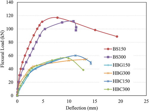
It is observed from that the load–deflection curves of all the tested beam specimens showed tri-linear behaviour. The stiffness of the tested beam specimens was found to be influenced by the type of reinforcement and spacing of the shear stirrups.
It is observed from that the initial stiffness of the tested beams BS150&, BS300, and HBC150 & HBC300 can be assumed to be nearly the same irrespective of the spacing of the shear stirrups. However, shows that the initial stiffness of the tested beams HBG150 and HBG300 was found to be influenced by the spacing of the shear stirrups. The initial stiffness of the beam specimen HBG300 was more than that of the beam specimen HBG150.
With the increase in the applied flexural loading beyond the first crack load of the tested beam specimens, the flexural stiffness of the tested beams decreased linearly due to the formation and widening of cracks. Critical observation of indicated that even with increased loading magnitude (beyond first crack load), the stiffness of the beam specimen HBG150 was more than that of the beam specimen HBG300 till ultimate load. However, test results () showed that, in general, the stiffness of the beam specimens HBG300 and HBC300 was more than the beam specimens HBG150 and HBC150, respectively. The reason for this observation could be attributed due to the difference in the failure modes of the beam specimens HBG300 and HBC300 as compared to that of the beam specimens HBG150 and HBC150. Since the failure mode of the beam specimens HBG300 and HBC300 was similar to that of deep beams, their behaviour was slightly stiffer (due to relatively less ductile behaviour) than the beam specimens HBG150 and HBC150, respectively.
5.5. Flexural toughness
The flexural toughness of the tested beam specimens was obtained as the area under the load–deflection curves and is given in . The variation in the flexural toughness of the tested beams is also shown in .
Figure 12. Variation in flexural toughness of tested beam specimens
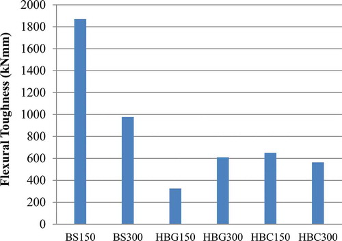
It is observed from and that, irrespective of spacing of shear stirrups, the flexural toughness of the beam specimens BS150 and BS300 with conventional steel reinforcement was more than that of other beam specimens consisting of SFCB as reinforcement. Among the beam specimens with SFCB as reinforcement, HBC150 achieved higher flexural toughness.
6. Numerical analysis results
Comparison of failure modes of beam specimens BS150, HBG150 and HBC150 obtained from the numerical simulation and experiment is shown in .
Figure 13. Comparison of failure modes
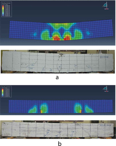
Figure 13. (Continued)
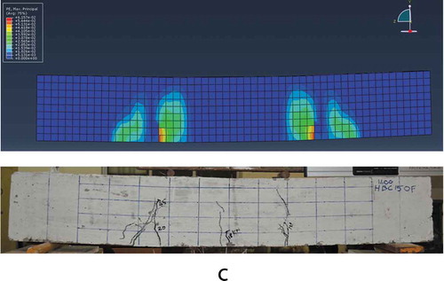
It is observed from that the numerical models developed are able to predict the flexural failure of beam specimen BS150 and failure due to combined shear-flexural stresses of the beam specimens HBG150 and HBC150. Comparison of load–deflection curves of the beam specimens BS150, HBG150 and HBC150 obtained from numerical simulation and experiment is shown in .
Figure 14. Comparison of load–deflection curves
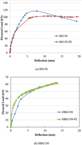
Figure 14. (Continued)
It is observed from ) that the load–deflection curves of beam specimen BS150 obtained from numerical analysis and experiment are comparable. However, it is observed from ) that the initial stiffness of the beam specimens HBG150 and HBC150 as obtained from the numerical analyses was more than that obtained experimentally. The deviation was more for beam specimen HBG150 than that for the beam specimen HBC150. Comparison of experimental ultimate flexural load and as obtained from the numerical analyses of the tested beams BS150, HBG150 and HBC150 is shown in .
Table 4. Comparison of ultimate flexural loads
It was observed from the predicted ultimate flexural load of beam specimen BS150 was 7% less than the experimental results. The predicted ultimate flexural load of the beam specimens HBG150 and HBC150 was 10% and 4%, respectively, more than the experimental results. In general, the results indicated that the predicted ultimate flexural load of the beam specimens was within ±10%.
7. Summary and conclusions
In this paper, experimental and numerical studies conducted on the flexural behaviour of fibre-reinforced concrete beams consisting of conventional steel bars or innovative hybrid bars in the tension zone were presented. Experimental study consisted of testing six concrete beam specimens with conventional steel bars, hybrid bars produced with glass fibres and hybrid bars produced with carbon fibres. Two different spacings of shear stirrups were considered. The conclusions based on the experimental and numerical studies presented in this paper are summarized below.
Hybrid reinforcement consisting of FRP wrapping over steel core area can be considered as a suitable alternative to conventional steel reinforcement towards improving the lifespan of reinforced concrete structures located in a corrosive environment.
The flexural behaviour of concrete beams specimens was influenced by the type of reinforcement used in the tension zone.
The beam specimens with hybrid reinforcement failed either due to shear-flexural stresses interaction or due to shear depending upon the spacing of the shear stirrups.
The numerical models developed were able to predict the ultimate flexural load comparable to the concrete beam specimens BS150, HBG150 and HBC150 with reasonable accuracy.
Further research is required in this area towards developing design guidelines.
Disclosure statement
No potential conflict of interest was reported by the authors.
Additional information
Notes on contributors
Sivaramakrishnan Subbaram
Sivaramakrishnan Subbaram, corresponding author, is working as a assistant professor in Sri Sairam Institute of Technology Chennai.
Chinnaraju Komarasamy
Chinnaraju Komarasamy, is working as Professor in College of Engineering Guindy. The first author is doing Ph.D under the guidance of second author.
References
- Abed, F., C. Oucif, Y. Awera, H. H. Mhanna, and H. Alkhraisha. 2020. “FE Modeling SFCB Reinforced Beams Can Be Very Useful in Marine Environment Where Chloride Induced Corrosion of Reinforcing Bars Form a Severe Threat to Durability of RCC Structures. Of Concrete Beams and Columns Reinforced with FRP Composites.” Defence Technology. doi:https://doi.org/10.1016/j.dt.2020.02.015.
- Aldabagh, S., F. Abed, and S. Yehia. 2016. “Effect of Fibers on the Flexural Behaviour of Concrete Beams Reinforced with MMFX Bars.” The 95th TRB Annual Meeting, Washington, DC, January 10-14.
- Al-Rahmani, A., and F. H. Abed. 2013. “Numerical Investigation of Hybrid FRP Reinforced Beams.” Proceedings of the fifth international conference on modeling, simulation and applied optimization (ICMSAO), Hammamet, Tunisia: IEEE, April 28 –30.
- Bencardino, F., A. Condello, and L. Ombres. 2016. “Numerical and Analytical Modeling of Concrete Beams with Steel, FRP and Hybrid FRP-steel Reinforcements.” Composite Structure 140 (40): 53–65. doi:https://doi.org/10.1016/j.compstruct.2015.12.045.
- D D, D., A. A. Pisano, and P. A. Fuschi. 2014. “FE-based Limit Analysis Approach for Concrete Elements Reinforced with FRP Bars.” Composite Structures 107: 594–603. doi:https://doi.org/10.1016/j.compstruct.2013.08.039.
- Farrag, S., and S. Yehia 2015. “Effect of Steel, Synthetic, and Hybrid Fiber Reinforcement on Properties of Self-compacted Concrete.”The 5th annual international conference on construction materials (CONMAT’15), Whistler, Canada, August 19-21.
- Ferreira, A. J. M., P. P. Camanho, A. T. Marques, and A. A. Fernandes. 2001. “Modelling of Concrete Beams Reinforced with FRP Re-bars.” Composite Structure 53 (1): 107–116. doi:https://doi.org/10.1016/S0263-8223(00)00182-3.
- Fib Model Code for Concrete Structures. 2010. Wiley.
- Graham, C. J., and A. Scanlon. 1986. Deflection of Reinforced Concrete Slabs under Construction Loading, SP-86. Detroit: American Concrete Institute.
- Güneyisi, E., T. Özturan, and M. Gesolu. 2006. Performance of Plain and Blended Cement Concretes against Corrosion Cracking, in Measuring, Monitoring and Modeling Concrete Properties - An International Symposium, pp. 189–198.
- Guo, Q., Q. Chen, Y. Xing, Y. Xu, and Y. Zhu. 2020. “Experimental Study of Friction Resistance between Steel and Concrete in Prefabricated Composite Beam with High-Strength Frictional Bolt.” Hindawi Advances in Materials Science and Engineering 13. doi:https://doi.org/10.1155/2020/1292513.
- Hawileh, R. 2014. “Finite Element Modeling of Reinforced Concrete Beams with a Hybrid Combination of Steel and Aramid Reinforcement.” Journal of Materials&Design. doi:https://doi.org/10.1016/j.matdes.2014.10.004.
- IS 456:2000. Indian standard Plain and Reinforced concrete/code of practice/Reaffirmed 2005
- Masmoudi, R., M. Theriault, and B. Benmokrane. 2001. “Flexural Behaviour of Concrete Beams Reinforced with Deformed Fiber Reinforced Plastic Reinforcing Rods.” ACI Structural Journal 95 (6): 665–676.
- Nour, A., B. Massicotte, E. Yildiz, and V. Koval. 2007. “Finite Element Modeling of Concrete Structures Reinforced with Internal and External Fibre-reinforced Polymers.” Canadian Journal of Civil Engineering 34 (3): 340–354. doi:https://doi.org/10.1139/l06-140.
- Rafi, M. M., A. Nadjai, and F. Ali. 2008. “Finite Element Modeling of Carbon Fiber-reinforced Polymer Reinforced Concrete Beams under Elevated Temperatures.” ACI Structural Journal 105 (6): 701–710.
- Saenz, L. P. 1964. “Discussion of Equation for Stress-strain Curve of Concrete.” ACI Structural Journal 61: 1229–1235.
- Saraswathy, V., and H. W. Song. 2008. “Evaluation of Cementitious Mortars for Corrosion Resistance.” Portugaliae Electrochimica Acta 26 (5): 417–432. doi:https://doi.org/10.4152/pea.200805417.
- Sivaraman, S., and K. Chinnaraju. 2019. “Flexural Behavior of Concrete Beams Reinforced with Innovative FRP Wrapped Steel Bars.” Journal of Structural Engineering (Madras) 46 (3): 200–212.
- Song, H. W., V. Saraswathy, S. Muralidharan, C. H. Lee, and K. Thangavel. 2009. “Corrosion Performance of Steel in Composite Concrete System Admixed with Chloride and Various Alkaline Nitrites.” Corrosion Engineering Science and Technology 44 (6): 408–415. doi:https://doi.org/10.1179/174327809X397848.
- Sun, Z., L. Fu, D. Feng, A. R. Vatuloka, Y. Wei, G. Wu, and B. Steel. 2019. “Experimental Study on the Flexural Behavior of Concrete Beams Reinforced with Bundled Hybrid steel/FRP Bars.” Engineering Structures 197: 109443. doi:https://doi.org/10.1016/j.engstruct.2019.109443.
- Toutanji, H. A., and D. Young. 2003. “Deflection and Crack-width Prediction of Concrete Beams Reinforced with Glass FRP Rods.” Construction and Building Material 17 (1): 69–74. doi:https://doi.org/10.1016/S0950-0618(02)00094-6.
- Toutanji, H. A., and M. Saafi. 2000. “Flexural Behaviour of Concrete Beams Reinforced with Glass Fiber-reinforced Polymer (GFRP) Bars.” ACI Structural Journal 97 (5): 712–719.
- URL-1. “Nace International, Corrosion Costs and Preventive Strategies in the United States.” Accessed 9 March 2020. http://impact.nace.org/documents/ccsupp.pdf
- URL-2. Accessed 19 May 2020. https://saylordotorg.github.io/text_general-chemistry-principles-patterns-and-applications-v1.0/s23-06-corrosion.html
- Xu, J., P. Zhu, Z. John, and W. Qu. 2019. “Fatigue Flexural Analysis of Concrete Beams Reinforced with Hybrid GFRP and Steel Bars.” Engineering Structures 199: 109635. doi:https://doi.org/10.1016/j.engstruct.2019.109635.
- Yehia, S. 2012. “Evaluation of Steel Fiber Distribution in a Concrete Matrix.” The ICCRRR 2012, Cape Town, South Africa, Sep 3–5, 2012, 506–507. CRC Press.
- Yehia, S., A. Douba, O. Abdullahi, and S. Farrag. 2016. “Mechanical and Durability Evaluation of Fiber-reinforced Self-compacting Concrete.” Construction and Building Materials 121: 120–133. doi:https://doi.org/10.1016/j.conbuildmat.
- Yehia, S., O. AbdelGhani, S. Farrag, A. Eltayib, and Z. Abdelrahim. 2015. “Impact of Synthetic Fibers on the Properties of Self-compacting Lightweight Concrete.” The 5th Annual International Conference on Construction Materials (CONMAT’15), Whistler, Canada, August 19-21.
- Zhao, D., J. Pan, Y. Zhou, L. Sui, and Z. Ye. 2020. “New Types of steel-FRP Composite Bar with Round Steel Bar Inner Core: Mechanical Properties and Bonding Performances in Concrete.” Construction and Building Materials 242: 118062. doi:https://doi.org/10.1016/j.conbuildmat.2020.118062.
- Zhao, Q., J. Yu, G. Geng, J. Jiang, and X. Liu. 2016. “Effect of Fiber Types on Creep Behavior of Concrete.” Construction and Building Materials 105: 416–422. doi:https://doi.org/10.1016/j.conbuildmat.
- Zhou, Y., B. Zheng, L. Sui, F. Xing, P. Li, and H. Sun. 2019. “Effects of External Confinement on Steel Reinforcement Corrosion Products Monitored by X-ray Microcomputer Tomography.” Construction and Building Materials 222: 531–543. doi:https://doi.org/10.1016/j.conbuildmat.2019.06.119.