
 ?Mathematical formulae have been encoded as MathML and are displayed in this HTML version using MathJax in order to improve their display. Uncheck the box to turn MathJax off. This feature requires Javascript. Click on a formula to zoom.
ABSTRACT
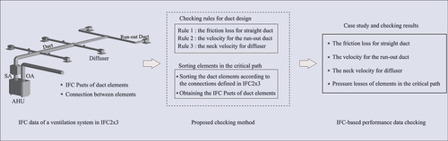
With the development of Building information modelling (BIM) tools, the non-geometric attributes of duct elements, such as size, flow rate, and pressure loss, can be exported directly. BIM has been used in numerous building projects. However, there is no clarity in checking the performance data in mechanical, electrical, and plumbing design using the Industry Foundation Classes (IFC) data. In this study, the IFC definitions for duct system, element, distribution port, and user-defined IFC-property set (Pset) according to the IFC2x3 specification are introduced. Based on the design criteria for ventilation system, three checking rules for friction loss, duct velocity, and the diffuser’s neck velocity are extracted. A sorting algorithm for duct elements in the ventilation system is proposed by searching the connections between duct elements and the related distribution ports. Furthermore, the critical path is determined by comparing path lengths from different diffusers to the AHU. Therefore, the IFC-based performance data checking for the duct design is proposed. A case study is also presented. The results show that the performance data of the duct elements in the critical path meet the design criteria, and the total pressure loss of the ventilation system is calculated.
Graphical abstract
1. Introduction
Building information modelling (BIM) has been used in numerous construction and facility management projects. The essential characteristic of BIM is how to use the attributes of building elements, which can be divided into two types: geometric and non-geometric forms. The geometric attributes are the size, volume, shape, height, and orientation, whereas the non-geometric attributes are the system data, performance data, regulatory compliance, specifications, and cost (Building and of Singapore CA Citation2013a). The Industry Foundation Classes (IFC) specification developed by buildingSMART has been accepted as an ISO standard (ISO16739:2013) since March 2013 (NBS Citation2018). It is a platform-neutral, open-file format specification for data exchange in the building industry.
Using IFC mapping files, BIM tools can export or import IFC files for building models. BIM model checkers, such as Solibri Office (Solibri Citation2020), BIMVision (Datacomp Citation2021), and Navisworks Manage (Autodesk Citation2020), can deal with the IFC data, visualise the 3D model, and display the IFC attributes of building elements. In the BIM survey completed by the UK National Building Specification (NBS) in 2020, 62% of the surveyed professionals stated “exchanging information in IFC format” (NBS Citation2020). Clash detections between mechanical, electrical, and plumbing (MEP) models as well as architectural and structural models can be implemented using the geometric IFC data of building elements.
However, there are few applications in using non-geometric IFC data, especially the attributes of the MEP systems. Sandy stated that ductwork had a significant impact on the total cost and performance of an air distribution system (Jorens, Verhaert, and Sörensen Citation2018). Brent compared the 15-year life cycle cost in two houses and demonstrated that lower pressure ductwork systems generally had small cost savings than the higher-pressure systems (Stephens Citation2014). The duct design, especially the pressure loss calculation, is crucial in duct systems. In contrast, noise control in the occupied zone is also significant. The air velocities at the neck of the supply diffusers or return registers should be checked against the velocities recommended by the American Society of Heating, Refrigerating, and Air-Conditioning Engineers (ASHRAE) or other duct design guides. The maximum recommended air velocity at the neck of the supply diffuser is 2.8 m/s in the office room with a noise rating of RC[N]40 (ASHRAE Citation2019, Citation2017). The MEP designer should calculate the total pressure loss carefully to ensure the air volume at the most remote diffuser from the fan and check the friction loss and duct velocity simultaneously.
With the development of BIM tool, the non-geometric attributes of MEP elements, including the performance data of duct elements, such as size, flow rate, and pressure loss, can be exported as IFC-property sets (Psets) (Autodesk Citation2021). In this study, a data checking solution for duct design is studied using the Psets exported by a BIM tool.
2. Literature review
2.1. BIM-based data check
There are many pilot projects and practices for BIM-based data checking. CORENET e-submission system is the most famous Government to Business (G2B) internet-based system (Building and of Singapore CA Citation2016c), which enables industry professionals to submit project-related electronic plans and documents to regulatory authorities for approval in Singapore. It has also extended its service to accept voluntary BIM e-submissions in native BIM format since October 2016 (for architectural plans) and October 2017 (for civil, structural, and MEP engineering plans) (Building and of Singapore CA Citation2016a). According to the MEP requirements for air-conditioning and mechanical ventilation system/environmental control systems in the code of practice for BIM e-submission (Building and of Singapore CA Citation2016b), full BIM 3D models for all systems in public shelters should be submitted, including the related rooms, equipment, accessories, and service routings. Using the BIM tool Revit, sizing MEP elements, including duct sizing and pressure loss calculation, are suggested in the BIM Essential Guide for MEP Consultants (Building and of Singapore CA Citation2013b). However, the details of the non-geometric attributes for BIM elements are not discussed.
ByggSøk is the Norwegian solution for electronic communication in building application processing, with the first version launched in 2003. The builder can fill out the application and send it via the Internet to the Norwegian Building Authority for approval. In the future, complete e-submission will be realised at the development progress of Step 4, and then the attachment will be computer analysed (Hjelseth Citation2015). The KBim Assess-Lite is an IFC-based BIM quality assessment tool. Based on Korean building regulations and codes, BIM models can be reviewed for building code compatibilities and general errors from the early design phase until submissions (Choi and Kim Citation2017).
What properties or BIM information should or can be used? Different designers/constructors have other responses during different phases of a building project. In the Level of Development (LOD) Specification 2019 released by BIMForum (AGC Citation2019), LOD 400 elements are modelled with sufficient detail and accuracy information for fabrication and installation, for example, size, shape, location, quantity, and orientation. Detailed non-graphic information has not been specified even in the LOD 500.
Construction operations building information exchange (COBie) is a performance-based specification for facility asset information delivery, focused on the operation and maintenance of equipment (US ARMY Corps of Engineers et al. Citation2021). Based on the COBie framework, a fire safety equipment inspection and maintenance system was proposed by combining BIM information and augmented reality (AR) environments (Chen, Lai, and Lin Citation2020). The UK National Building Specification (NBS) developed a BIM object standard based on information, geometry, and function requirements. It provides a BIM library from building fabric systems to mechanical and electrical objects (NBS Citation2019). Users can download the BIM templates for the air handling unit (AHU), diffuser, and other equipment, including the specified IFC Psets. Therefore, one can use Psets of BIM objects.
Regarding the BIM project objective described in the Singapore BIM Guide (Building and of Singapore CA Citation2013a), in the detailed design phase, a generalised building component or system with accurate dimensions, shape, location, orientation, and quantity should be provided, including the non-geometric properties. It also points out that although BIM model authors have checked the model’s accuracy and quality before sharing it with model users, the model users should use the BIM model for reference, as well as verify and confirm the accuracy of the model. This also shows that there is a clear need for checking the BIM model from the industry.
2.2. Duct design criteria for ventilation system
The duct design aims to construct an air distribution system without objectionable noise and to realise the minimum life-cycle cost (LCC). Noise can be controlled by limiting the duct velocity to the values recommended by ASHARE. Referring to the recommended maximum duct velocities listed in , in general offices, the air velocity in the main duct is lower than 7.5 m/s, and lower than 3.5 m/s in the run-out duct.
Table 1. Recommended maximum duct velocities and noise rating for low-pressure ductwork system.
The design criteria listed in were used in this study to check the performance data of the duct elements.
Table 2. Performance data of duct elements checked.
For low-pressure systems, the values for the constant pressure loss rate are in the range of 0.8–1.2 Pa/m (CIBSE Citation2016). Consequently, the maximum pressure loss rate was set to be 1 Pa/m. The LCC of a duct system depends on the electricity consumption of the AHU/fan, which is mainly affected by the total pressure and flow rate. It is important to check the related performance data of a duct system. According to the BIM model exported by Revit, the IFC definitions of duct, fitting and diffuser, including the Psets were exemplified, which shows that these property data of duct elements are available for duct design (Xu Citation2020). However, until now, there have been few applications in checking these performance data.
Focused on the following research questions, IFC-based performance data checking for ventilation systems is proposed:
How to use the Psets to check the performance data?
How about the algorithm of checking?
The proposed checking algorithm for duct design forms the critical contribution of this study.
3. Basic knowledge of IFC data for ventilation system
3.1. Definitions of duct elements and systems
According to the IFC2x3 specification (buildingSMART Citation2007), duct elements in a ventilation system including the fan or AHU are defined by the sub-types of IfcDistributionFlowElement class shown in .
Table 3. Sub-types of IfcDistributionFlowElement for duct elements.
Depending on the BIM tool used, the damper, silencer, fan, or AHU can also be exported as the IfcBuildingElementProxy class.
The Psets of a duct element is defined by the IfcRelDefinesByProperties class, which can be searched from the INV: IsDefinedBy (inverse attribute with the name of IsDefinedByFootnote1) of the element. The related properties, such as flow rate, pressure drop, and ventilation velocity can be exported. As Pset of an element can be defined by the user or vendor of BIM tool, it is also called the user-defined Pset or property.
A system is defined by the IfcRelAssignsToGroup, which has the following obligatory attributes:
RelatedObjects attribute defines a set of IfcElements contained in the system.
RelatingGroup attribute defines the name and object type of the system.
3.2. Connection between duct elements
The connection between duct elements is defined by the IfcRelConnectsPortToElement class, which can be obtained from the INV:HasPorts (inverse attribute with the name HasPorts) of the duct element. IfcRelConnectsPortToElement has a RelatingPort attribute, which is a port and defines the air flow direction of the duct element (buildingSMART Citation2013). When the FlowDirection attribute of port is “SOURCE”, it means outgoing flow, whereas “SINK” means incoming flow.
When the duct element has only one IfcRelConnectsPortToElement, it is a diffuser or louvre. When it has two IfcRelConnectsPortToElements, there are two ports, one is at the inlet and the other is at the outlet. When it has more than two IfcRelConnectsPortToElements, there are diverging or merging flows, which means it is a tee or cross fitting.
illustrates an instance of tee (named Tee) and the connected ducts upstream and downstream in a supply air (SA) system. Tee is defined by IfcFlowFitting(#7734Footnote2) and There are three ports connected with this tee, among which only one port has a different flow direction. The flow direction of IfcDistributionPort(#10253) is “SINK”, which is different from the other two. Therefore, IfcDistributionPort(#10253) is the upstream port of Tee. The upstream IfcRelConnectsPorts(#10267), IfcDistributionPort(#10262), IfcRelConnectsPortToElements(#10264), and the upstream duct (Upstream Duct0) defined by IfcFLowSegment(#5890) are also illustrated.
Figure 1. Instance of tee and the connected ducts upstream and downstream.
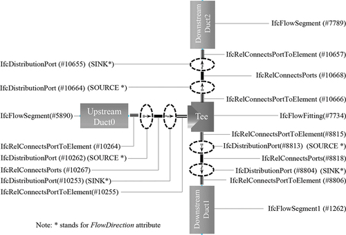
There are two diverging flows at Tee. One goes to Downstream Duct1 defined by IfcFlowSegement(#1262), and the other to Downstream Duct2 defined by IfcFlowSegement(#7789). There are two paired ports between Tee and Downstream Duct1, one is IfcDistributionPort(#8813), and the other is IfcDistributionPort(#8818).
4. Algorithm of IFC-based duct design criteria checking
4.1. Checking rules for duct design
Based on the design criteria for duct systems listed in , thePsets of duct elements shown in are used in this study, which are exported by the BIM tool.
Table 4. Psets exported by the BIM tool.
Referring to the design criteria listed in , three checking rules for duct design were established. For a general office building with low-pressure duct systems and the maximum allowable noise rating (NR) of 35–40. The details are shown as follows:
Rule 1: The friction loss for straight duct is smaller than 1 Pa/m.
With Psets of pressure loss and length of a straight duct, the friction loss Floss (Pa/m) can be calculated using EquationEquation 1(1)
(1) :
Here,
ΔP is the pressure loss of a straight duct;
L is the length of a straight duct.
Rule 2: The duct velocity for the run-out duct is lower than 3 m/s, for a branch lower than 5.5 m/s, and for a main duct lower than 6 m/s.
The duct velocity is obtained from the Pset of velocity.
Rule 3: The neck velocity for the diffuser is lower than 2.8 m/s.
From the Psets of neck/collar dimension and flow rate of a diffuser, the neck velocity of the diffuser Vneck (m/s) can be calculated using EquationEquation 2(2)
(2) :
Here,
Q is the flow rate of the diffuser;
ANeck is the neck or collar area of the diffuser.
4.2. Sorting the duct elements in the critical path
The pressure loss of the ventilation system is calculated by adding up all the losses caused by friction and dynamic losses at all duct elements in the duct path. First, it is essential to sort the duct elements from the AHU to the most remote diffuser.
Using the IFC data of a ventilation system exported by the BIM tool, the sorting algorithm of duct elements in the SA system is expressed as follows:
Step 1: Search each IfcRelAssignsToGroup
Search each IfcRelAssignsToGroup in the IFC file and obtain the system name and object type from the RelatingGroup attribute and the related duct elements from the RelatedObjectsattribute. For supply system, the object type will be “Supply”, while it is “Outdoor” for OA system.
Step 2: Sort the elements in a duct path from each diffuser to the AHU
As the path begins from a diffuser and ends with the AHU, referring to the connection between the duct elements explained in Section 3.2, the sequence of elements for each duct path can be sorted as shown i12n .
Figure 2. Flowchart for sorting the elements in a duct path.
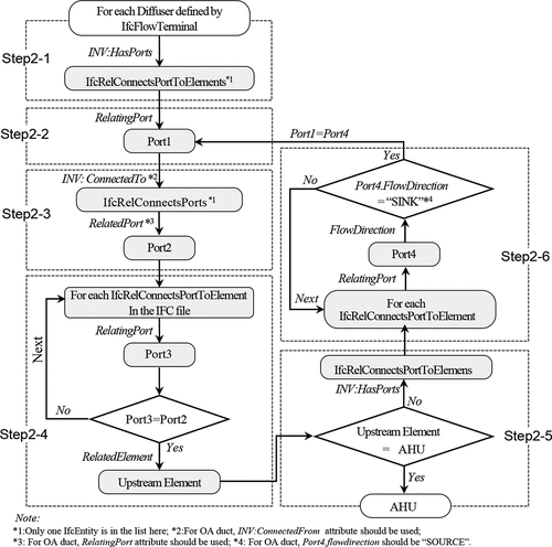
Step 2–1: Search an IfcFlowTerminal among the related duct elements obtained in Step 1. From the INV:HasPorts of the IfcFlowTerminal, we obtain IfcRelConnectsPortToElement.
Step 2–2: From the RelatingPort attribute of IfcRelConnectsPortToElement, we obtain Port1 defined by the IfcDistributionPort class.
Step 2–3: From the INV:ConnectedTo of Port1, first obtain the IfcRelConnectsPorts. Then, from the RelatedPort attribute, we obtain Port2.
Step 2–4: Search each IfcRelConnectsPortToElement in the IFC file and set its RelatingPort attribute to be Port3 until Port3 is equal to Port2. From the RelatedElement attribute of the IfcRelConnectsPortToElement searched, we obtain the upstream element (name Upstream Element) and its “Mechanical-Flow” Pset.
Step 2–5: If the upstream element is equal to the AHU, it comes to the end of the path. If not, from the INV:HasPorts of Upstream Element, we obtain a collection of IfcRelConnectsPortToElements.
Step 2–6: Search each IfcRelConnectsPortToElement in IfcRelConnectsPortToElements acquired in Step 2–5 and set its RelatingPort attribute to be Port4 until the flow direction of Port4 is equal to “SINK”. Subsequently, Port1 is set to be Port4.
For an OA system, the flow direction is “SOURCE”.
Continuing from Step 2–2 to Step 2–4, all the other duct elements can be found until the upstream element is the AHU. Therefore, all Elements with Psets in the same path are sorted.
Step 3: Continue the sorting process described in Step 2 until all the paths are sorted.
Step 4: Determine the critical path
Compare the length of each duct path obtained in Step 3 to determine the critical path. Add up each straight duct’s length in each path, and the longest one is the critical path.
As for the OA system, in Step 2–3, from the INV:ConnectedFrom of Port1, the related IfcRelConnectsPorts is obtained. Use, the RelatingPort attribute of the acquired IfcRelConnectsPorts to obtain Port2. In Step 2–6, the value of Port4.FlowDirection (FlowDirection attribute of Port4) is “SOURCE”. Therefore, all elements in the OA system can be sorted.
4.3. Implementation of the checking rules
With the three rules proposed in Section 4.1, the performance data of the elements in the critical path were checked. The total pressure loss of the system was calculated using EquationEquation 3(3)
(3) :
Here,
is the Pset of pressure loss of element i in the critical path of SA;
is the Pset of pressure loss of element i in the critical path of OA;
m is the total number of elements in the critical pathof SA;
n is the total number of elements in the critical path of OA.
The IFC-based performance data checking for duct design is implemented by C# (Microsoft) programming, along with IFCsvr.300, a free ActiveX component for handling IFC data developed by SECOM Co., Ltd.
5. Case study
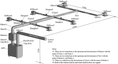
5.1. IFC data of a ventilation system
An instance of a ventilation system shown in was designed using a BIM tool (Revit 2020 with the plug-in MagiCAD). It comprises of an OA system and a supply system with six diffusers, a silencer, an AHU, and an external louvre. The flow rate of each diffuser was 0.03 m3/s. The ventilation system is supposed to be installed in a general office building with the noise rating of NR 35–40.
Figure 3. Instance of a ventilation system.
5.2. Psets exported by a BIM tool
The duct sizes and pressure drops of all duct elements are designed within MagiCAD (MagiCAD Group Citation2019).According to the IFC setup option of “IFC2x3 Coordinate View 2.0” provided by the BIM tool, Psets shown in were exported. The length, flow rate, and pressure loss are in meter, cubic meter per second, and pascal.
5.3. Checking results
There are six SA paths and one OA path in this ventilation system. Referring to the three rules proposed in Section 4.1, the duct systems were checked using the Psets exported by the BIM tool. According to the sorting method proposed in Section 4.2, the critical path for SA starts from the AHU and ends at Diffuser1. The checking results and performance data of the elements in the critical path are listed in , including the identification number (P21id) of each IfcElement.
Table 5. Performance data of duct elements in the critical path and the checked results.
The detailed checking results are shown as follows:
The maximum friction loss for a straight duct is 0.85 Pa/m, which is smaller than 1 Pa/m, the value described in Rule 1.
The duct velocity of Duct1 (the run-out duct) is 2.4 m/s, which is lower than 3 m/s, the value described in Rule 2.
The neck velocity of Diffuser1 is 1.49 m/s, which is lower than 2.8 m/s, the value described in Rule 3.
According to EquationEquation 3(3)
(3) , the pressure losses of elements in the critical path are added up. The system’s total pressure loss is 165.9 Pa, 96.6 Pa for SA, and 69.3 Pa for OA. The pressure drop for each element is also listed in .
6. Discussion and conclusions
6.1. Discussion
Referring to the proposed checking algorithm, the performance data a ventilation system are checked using the IFC data. Results of case study show that this system meets the three checking rules proposed. The elements in the critical path are determined by the the sorting method proposed, and the total pressure loss in the critical path is calculated using the Pset of pressure loss of each element.
The pressure losses of the straight duct agree with the values from the ASHRAE fitting database (ASHRAE Citation2016), but the total pressure loss calculated from Psets was approximately 16% larger. The reasons are provided below.
Larger pressure loss of the cross in Pset.
The pressure losses at Cross1 (inlet Φ250, outlet Φ250, branch1 Φ125, branch2 Φ125, including Reduc.2: inlet Φ250, outlet Φ160) differ with the flow directions. According to the ASHRAE fitting database, the loss in the main direction is 1 Pa, and 6 Pa in each branch direction. However, the BIM tool used in this study only exports one pressure loss in the Pset, with the value of 4.3 Pa.
Larger pressure of the elbow in Pset.
The pressure loss of Elbow1 (Φ125, 90 degrees, r/D = 1.5) is 3.1 Pa, while it is 1 Pa from ASHRAE. The BIM tool uses the data from the manufacturer, which are larger than those in the ASHRAE database.
Therefore, a more detailed Pset of pressure loss for fitting should be defined, especially the pressure losses in the main flow direction and the branch direction should be distinguished. There are 317 types of property sets (Psets) defined in the IFC2x3 specification, among which the pressure loss of fitting is defined by the Pset_DuctFittingPHistory with the name of lossCoefficient. For a diverging or junction fitting, the pressure losses differed in the flow directions. It is necessary to define the detailed pressure losses for duct fittings. Furthermore, the source and the reliability of the values in Psets should be clearly stated, which is an essential factor in MEP design.
6.2. Conclusions
The key feature of BIM is how to use the attributes of the building elements. The literature reviewed has no clarity regarding how to check the performance data in the MEP design. In this study, the IFC definitions for duct system, element, distribution port, and user-defined Pset according to the IFC2x3 specification were introduced. Based on the design criteria for duct systems, three checking rules for friction loss, duct velocity, and the diffuser’s neck velocity were extracted. A sorting algorithm for duct elements in the ventilation system was developed by searching the connections between duct elements and the related distribution ports. The critical path was determined by comparing the path length. Therefore, the IFC-based performance data checking for duct design was proposed using these Psets of duct elements in the critical path.
A case study utilised the IFC Psets to check the performance data for a simple ventilation system in a general office building was presented. The results show that the performance data of the duct elements meet the design criteria, and the total pressure loss of the whole system is calculated from Psets. Although the the pressure loss is larger than the value calculated using the ASHRAE fitting database, the differences are also identified. Therefore, the source and the reliability of the performance data defined in Psets should be clarified.
Psets are user-defined properties, however, there is no standard rule to define the IfcPropertySets related to duct design. In the future, these duct design criteria related to Psets should be standardised, which will save time to search the properties and improve the quality of MEP design. The standardisation of user-defined Psets is also expected in the activities of buildingSMART International. Furthermore, the IFC-based performance data checking proposed in this study will be updated according to the IFC4 specification.
Disclosure statement
No potential conflict of interest was reported by the author(s).
Additional information
Funding
Notes on contributors
Lei Xu
Dr. Lei Xu is a Professor at the Faculty of Architecture, Tohoku Institute of Technology. He received his BSc degree from East China Institute of Technology, Nanjing in 1992, MSc degree from Tongji University, Shanghai in 1998, and PhD degree from Waseda University, Tokyo in 2003.
Yoshinobu Adachi
Dr. Yoshinobu Adachi is a Senior Manager at Office of BIM Development, KAJIMA Corporation. He has been active in openBIM establishment in buildingSMART International since 1998, contributing to the development of the Industry Foundation Classes (IFC) standard. In 2017 he was awarded a buildingSMART Fellow.
Notes
1 Italic word, such as RelatedObjects refers to the attribution name of IfcEntity.
2 #Num is the line number of the IfcEntity in the IFC file, which is also called the P21id of STEP file.
References
- AGC. 2019. “Level of Development (Lod) Specification Part 1 & Commentary for Building Information Models and Data.” Accessed 20 February 2021. https://bimforum.agc.org/wp-content/uploads/sites/27/2020/04/3.12.20-LOD-Spec-2019-Part-I-and-Guide-2019-04-29.pdf
- ASHRAE. 2016. ASHRAE Duct Fitting Database (version: 6.00.05.10). ASHRAE software.
- ASHRAE. 2017. “Duct Design.” In ASHRAE Handbook-Fundamentals (SI ed., 21,22). Atlanta: ASHRAE.
- ASHRAE. 2019. “Noise and Vibration Control.” In ASHRAE Handbook-HVAC Applications (SI ed., 49,15). Atlanta: ASHRAE.
- Autodesk. 2020. “Navisworks 2021 Learning.” Accessed 5 February 2021. https://help.autodesk.com/view/NAV/2021/ENU/
- Autodesk. 2021. “About Revit and Ifc.” Accessed 20 May 2021. https://knowledge.autodesk.com/support/revit-products/learn-explore/
- Building and of Singapore CA. 2013a. “Singapore BIM Guide Version 2.” Accessed 26 February 2021. https://www.corenet.gov.sg/media/586132/Singapore-BIM-Guide_V2.pdf
- Building and of Singapore CA. 2013b. “BIM Essential Guide for MEP Consultants.” Accessed 20 February 2021. https://www.corenet.gov.sg/media/586155/Essential-Guide-MEP.pdf
- Building and of Singapore CA. 2016a. “Changes to Building Information Modelling (BIM) E-submission Requirements for Plan Submission to Bca.” Accessed 5 February 2021. https://www.corenet.gov.sg/media/2032998/circular-on-bim-e-submission-for-plan-submission-to-bca.pdf
- Building and of Singapore CA. 2016b. “Code of Practice for Building Information Modelling (Bim) E-submission: Mechanical, Electrical & Plumbing (Mep) Requirements.” Accessed 23 May 2021. https://www.corenet.gov.sg/media/2157491/4_cp_for_bim_esubmission_mep_v11.pdf
- Building and of Singapore CA. 2016c. “Corenet Esubmission System Faqs.” Accessed 5 February 2021. https://www.corenet.gov.sg/general/corenet-e-submission-system/corenet-e-submission-system-faqs.aspx#FAQ_final_1_1
- buildingSMART. 2007. “Ifc2x edition 3 technical corrigendum 1.” Accessed 5 April 2021. https://standards.buildingsmart.org/IFC/RELEASE/IFC2x3/TC1/HTML
- buildingSMART. 2013. “Definition of Ifcbuildingelementproxy in IFC4.” Accessed 6 February 2021. https://standards.buildingsmart.org/IFC/RELEASE/IFC4/ADD1/HTML
- Chen, Y. J., Y. S. Lai, and Y. H. Lin. 2020. “Bim-based Augmented Reality Inspection and Maintenance of Fire Safety Equipment.” Automation in Construction 110: 103041. doi:10.1016/j.autcon.2019.103041.
- Choi, J., and I. Kim. 2017. “A Methodology of Building Code Checking System for Building Permission Based on Openbim.” In: ISARC. Proceedings of the International Symposium on Automation and Robotics in Construction. Taipei, Taiwan, volume 34, IAARC Publications, 945–950.
- CIBSE. 2016. “Ventilation and Ductwork.” In CIBSE Guide B2, 2–42,2–47. London: CIBSE.
- Datacomp. 2021. BIMVision: User Manual, Datacomp IT Sp. z o.o.
- Hjelseth, E. 2015. “Public BIM-based Model Checking Solutions: Lessons Learned from Singapore and Norway. Building Information Modelling (BIM) in Design.” Construction and Operations 149: 421–436.
- Jorens, S., I. Verhaert, and K. Sörensen. 2018. “Design Optimization of Air Distribution Systems in Nonresidential Buildings.” Energy and Buildings 175: 48–56. doi:10.1016/j.enbuild.2018.07.018.
- MagiCAD Group. 2019. MagiCAD for Revit 2020 User Guide, MagiCAD Group Oy.
- NBS. 2018. “Iso 16739-1:2018 industry foundation classes (ifc) for data sharing in the construction and facility management industries-part 1: Data schema.” Accessed 8 April 2021. https://www.iso.org/standard/70303.html
- NBS. 2019. “NBS BIM Object Standard V2.1.” Accessed 5 April 2021. https://www.nationalbimlibrary.com/en/nbs-bim-object-standard
- NBS. 2020. “10th National BIM Report.” Accessed 6 February 2021. https://www.thenbs.com/knowledge/national-bim-report-2020
- Solibri. 2020. “Solibri Puts You in Control of Model Quality.” Accessed 6 February 2021. https://www.solibri.com/our-offering
- Stephens, B. 2014. “The Impacts of Duct Design on Life Cycle Costs of Central Residential Heating and Air-conditioning Systems.” Energy and Buildings 82: 563–579. doi:10.1016/j.enbuild.2014.07.054.
- US ARMY Corps of Engineers et al. 2021. “Construction Operations Building Information Exchange (Cobie).” Accessed 15 April 2021. https://www.wbdg.org/bim/cobie
- Xu, L. 2020. “Information Analysis by Using the Ifc Data of Duct Systems.” Transactions of the Society of Heating, Air-Conditioning and Sanitary Engineers of Japan 283: 55–61.