
ABSTRACT
Current elevator landing door safety retainers are able to prevent fall accidents from an inadvertent bump against the door, as they are designed to endure a kinetic energy of 450 J. However, the recent increase in fall accidents among people in electric wheelchairs indicates that retainers are required to sustain stronger external shocks to prevent fall accidents against elevator landing doors. The purpose of this study is to develop elevator landing door safety retainers capable of enduring 1,000 J to prevent fall accidents of electric wheelchairs at the landing doors of elevators. In this study, crash analysis simulations were conducted after designing new scenarios that are not stated in the current regulations, considering the collision behavior of an electric wheelchair against an elevator landing door. The side hook was confirmed to play an important role in withstanding a collisional energy of 1,000 J. Crash analysis yielded different results according to the shape of the guide shoe. The analysis simulations were verified by performing experiments on various established scenarios. This study also confirmed the reliability of the developed safety retainers by implementing more realistic experiments on the crash of electric wheelchairs instead of the impactor proposed in the current regulations.
1. Introduction
The presence of architecture and building engineers is crucial for the creation of structures, particularly ones equipped with elevators, to guarantee the safety, convenience, and welfare of people (Jia et al. Citation2021; Lu-Xi et al. Citation2023; Xianmin et al. Citation2021; ZHANG et al. Citation2021, Citation2022). Ejection and fall accidents in elevator landing doors caused by external factors continue to occur and can lead to fatality. Hence, countermeasures against them should be identified. The European Union enacted the EN 81–20, 81–50 New European standard for lifts (BS EN 81–20 Citation2014; BS EN 81–50 Citation2014) and enforced it from 1 September 2017. The regulation mandates passing an impact test where a 45 kg soft-body pendulum is dropped from a height of 0.8 m, and a landing door assembly part should not generate a crack exceeding 0.12 m inside the elevator shaft. In the United States, ASME A17.1–2016 (ASME 17.1 Citation2016) does not allow an elevator door to develop a crack exceeding 20 mm at the top and bottom of the door when 5,000 N of impact is applied in the area range of 300 mm × 300 mm. It is assumed that a person weighing 111 kg can generate 5,000 N when the force is applied to the back, corresponding to a collision impact of 500 J when a person crashes at a speed of 3 m/s. With the adoption of safety inspection criteria for elevators in Korea, elevators installed after 10 September 2008, are required to have retainers in landing doors. The regulation mandates passing an impact test where a 45 kg soft-body pendulum is dropped from a height of 1.02 m, corresponding to a collision impact of 450 J. A landing door assembly part should not generate a crack exceeding 0.12 m inside the elevator shaft.
However, there is a growing need for safety retainers withstanding 1,000 J of impact. Currently, they can endure up to 450 J and are not able to ensure the safety of users considering the increasing use of electric wheelchairs. An impact energy of 1,000 J is generated when a person weighing 70 kg on a 100 kg electric wheelchair collides at a speed of 12 km/h. Despite importance, however, only a handful of safety retainers that can withstand 1,000 J of external impact have been developed globally. To develop a safety retainer that endures an energy of 1,000 J, the design capability should be improved using simulations. Simulations are being used in many engineering fields because they enable engineers to predict and analyze complex phenomena, which leads to the development of safer, more reliable, and innovative solutions (CAO et al. Citation2022; CHEN et al. Citation2021; Fei et al. Citation2022; HE et al. Citation2021; HUANG, LU, and ZHANG Citation2022; LI et al. Citation2021; WU et al. Citation2022; ZHAO et al. Citation2022; ZHIGUO et al. Citation2022). Several studies on elevator development have been carried out based on analysis simulations. Hubalovsky (HUBALOVSKY Citation2013) conducted a case study using the commercial finite element program SolidWorks for elevator cabs and enhanced the design efficiency of an elevator cab. Giagopoulos et al (GIAGOPOULOS, CHATZIPARASIDIS, and SAPIDIS Citation2018). utilized numerical analysis to optimize the design of elevators that operate under harsh conditions. They completed the optimization of the design by configuring a numerical model of elevators under harsh conditions. A comparison of the numerical and experimental data verified that the proposed “mixed computational-experimental” analysis method was quite reliable. Onur et al (ONUR and İ̇mrak Citation2012). applied finite element analysis to the design of an elevator car frame. The article presents the stress and deformation values of the car frame components and describes the optimal car frame design under the given conditions. Ahn et al (AHN, Jung, and Kim Citation2022). improved safety retainers by performing a crash analysis so that they could withstand strong external impacts. By proposing optimal values of the major design parameters of the guide shoe, the authors have presented a safety retainer that can withstand 1000 J of impact. However, an experimental verification of the developed crash analysis was not performed.
This study establishes new scenarios that are not stated in the current regulations considering the collision behavior of an electric wheelchair against an elevator landing door. Crash analysis simulations were conducted in these scenarios. The results of crash analysis simulations were verified through crash experiments. The final objective of this study was to secure the reliability of elevator landing door safety retainers by carrying out crash experiments with actual electric wheelchairs.
2. Model definitions
2.1. Landing door safety retainers
demonstrates the model of safety retainers selected for this study. shows a picture of the guide shoe and stopper. Guide shoes are attached to the bottom of an elevator door, and a stopper is installed inside the landing sill. When the door is closed, guide shoes are inserted between the stoppers to prevent detachment of the elevator door, as the guide shoe and stopper are interlocked if any impact is applied to the elevator door. There is no interference between the guide shoe and stopper when the door is opening and closing. shows a side hook installed on the side of the door. When the door is deformed owing to an impact, the side hook helps withstand the impact, as it is designed to be interlocked in the jamb to prevent the detachment of the landing door. Numerous researchers have recognized the significance of choosing appropriate materials to develop products with the desired performance, and they have undertaken investigations aimed at creating advanced materials (EQI et al. Citation2023; GAO et al. Citation2023; TONG et al. Citation2023; ZHAO et al. Citation2022). In this study, SUS304 materials with high tensile strength and elongation at break values were selected as the landing door safety retainers needed to effectively absorb a significant amount of energy without experiencing any damage or breakage.
Figure 1. Installation of elevator door safety retainers: (a) Guide shoe and stopper and (b) Side hook (ESEMS Website, Citation2023).
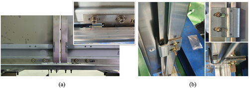
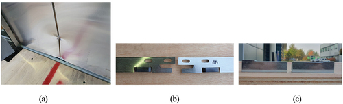
As shown in , flat- and hook-type guide shoes were used in this study. The flat-type in prevents the detachment of the guide shoe with the frictional force of the guide shoe and stopper, and the hook-type in helps prevent the detachment by inducing interlocking between the actual hook and the stopper.
Figure 2. Two types of guide shoes: (a) Flat-type and (b) Hook-type.
2.2. Safety rules for landing door safety retainers
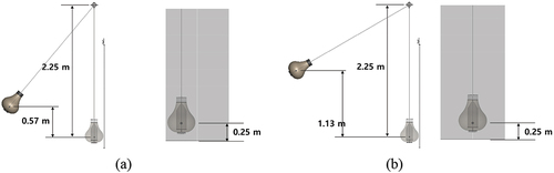
Collision scenarios for electric wheelchairs have been established following the study purpose of developing a safety retainer that prevents a landing door detachment by electric wheelchairs. First, assuming that a 70 kg person is on a 110 kg electric wheelchair, the weight of the colliding object was estimated to be 180 kg. Two collision scenarios were examined in this study. The first scenario in demonstrates the case in which an electric wheelchair crashes into the center of one side of the door. Considering the maximum speed of the electric wheelchair, the collision speed was set to 3.33 m/s. Accordingly, the drop height was 0.57 m, and the collision point of the electric wheelchair was 0.25 m considering the shape of the wheelchair. Under this condition, the impact energy generated from the dropped object was 1,000 J. In the second scenario shown in , the impact energy was set at 2,000 J, and it was assumed that an electric wheelchair hit the center of both doors.
Figure 3. Impact test scenarios: (a) Scenario A: 1,000 J at the center of one door and (b) Scenario B: 2,000 J at the center of both doors.
3. Numerical simulation
3.1. Finite element modeling
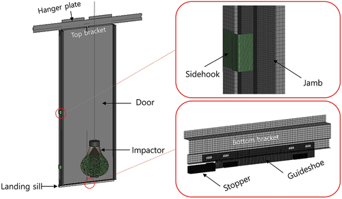
shows the finite element model of an elevator door with landing door safety retainers. The door is connected to a hanger plate, and brackets are located at the top and bottom of the door. The door is 800 mm in width and 2,100 mm in height and has a 1.5 mm thickness. A guide shoe is installed in the bottom bracket of the door, and the rubber attached to the guide shoe reduces vibration. A stopper is placed on the landing sill to induce interlocking with the guide shoe. A side hook is attached to the side of the door. The behavior of the impactor immediately before colliding with the door was not analyzed. Assuming that all potential energy is converted into kinetic energy immediately before collision, an initial velocity was applied to the leather bag filled with lead beads in the direction perpendicular to the door. A commercial finite element analysis solver, LS-DYNA, was utilized to conduct a crash analysis simulation. A constant stress solid element of 1 mm size was used in the guide shoe, stopper, side hook, and rubber because stress concentration was expected. A Belytschko Tsay shell element of 5 mm size was applied to the door, brackets, jamb, and landing sill. Given that a leather bag filled with lead beads was used as an impactor in the actual test, the individual behavior of lead was simulated using the discrete element method to create a similar behavior for analysis. Static and kinetic friction coefficients of 0.3 and 0.2 were applied, respectively.
Figure 4. Finite element model of an elevator door with elevator door safety retainers.
3.2. Results and discussion
In this study, Simulations were performed in the four scenarios listed in . Three scenarios were selected where an impact was applied to the center of one side door, and one scenario – where the object collided at the center of both doors. demonstrates the deformed shape of the door immediately after collision in each scenario. shows the deformed shapes of the stoppers and guide shoes for each scenario. Although the side hook plays an important role in preventing the detachment of doors, it could not be examined, as the degree of its deformation was small. The difference between scenarios A1 and A2 is in the side hook installation. The results show that the guide shoe detached from the stopper without a side hook, whereas with the side hook, the guide shoe did not detach from the stopper. Scenarios A1 and A3 both do not have a side hook; however, the type of guide shoe is different. In the case of the hook-type, the guide shoe did not detach from the stopper even without the side hook, unlike the flat-type. Given that scenario B1 assumes a case similar to the actual electric wheelchair collision, it is the result of applying a 2,000 J impact at the center of both doors considering the safety factors, and no detachment occurred.
Figure 5. Deformed shape of a door after impact: (a) A1, (b) A2, (c) A3, and (d) B1.
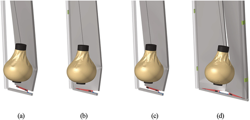
Figure 6. Deformed shape of a guide shoe and stopper after impact: (a) A1, (b) A2, (c) A3, and (d) B1.
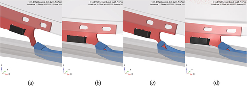
Table 1. Summary of each scenario.
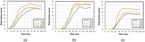
demonstrates the deformation of the main parts over time in each scenario. shows the deformation of the door. In scenarios A2 and B1 with the side hook, the amount of deformation is larger than in A1, and more collision energy is absorbed when the door is fixed. In scenario A3, the door is further deformed while being fixed by the hook-type guide shoe, and more collision energy is absorbed. shows the deformation of the guide shoe. As demonstrated by the deformation amount of the door, the deformation amount is larger while stably absorbing collision energy with the side hook. For the hook-type guide shoe, the deformation is noticeable as the guide shoe does not detach from the stopper without a side hook. shows the deformation of the stopper. In A3, the deformation amount of the stopper is the largest owing to the interlocking of the hook-type guide shoe and stopper. Although there is some oscillation, it can be seen that the deformation converges after about 60 ms.
Figure 7. Deformation of each part: (a) Door, (b) Guide shoe, and (c) Stopper.
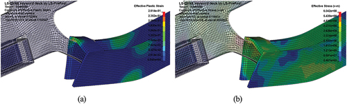
is the contour plot of guide shoe stress and strain in scenario B1, and is that of the stress and strain of the stopper. It can be seen that strain and stress are locally concentrated in the contact region of the guide shoe and stopper. Although some damage may be caused to the material, it is not to the extent that will affect the test result; thus, the fracture of the material was not considered in this study.
Figure 8. Contour plot of guide shoe: (a) Strain and (b) Stress.
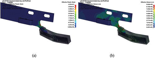
Figure 9. Contour plot of stopper: (a) Strain and (b) Stress.
4. Experimental verification
4.1. Impact test setup
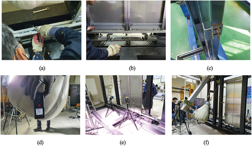
An impact test with 1,000 J has not been carried out at home or abroad. To conduct an impact test with 1,000 J in this study, test equipment and an impactor were manufactured, as demonstrated in . The landing doors to be tested were mounted in the impact test equipment, whereas the guide shoe and side hook were installed in the landing doors. By measuring the height of a 180 kg impactor, the energy at the collision point was assessed while observing the deformation behavior with a high-speed camera.
Figure 10. Impact test setup: (a) Installment of the stopper, (b) Installment of the guide shoe, (c) Installment of side hook, (d) Impactor height setup, (e) High-speed camera, and (f) Total impact test setup.
4.2. Comparison with the numerical simulation
The results of the impact tests and simulations were then compared. compare the experiment and simulation of the deformation behavior of the stopper and guide shoe, respectively, after the impact test in scenario A2. The results demonstrate that the deformation has been generated in a highly similar shape. Furthermore, it is confirmed that the guide shoe is well interlocked with the stopper, preventing detachment, similar to the expected result in the simulation.
Figure 11. Deformation shape of the stopper after impact: (a) Experiment and (b) Simulation.
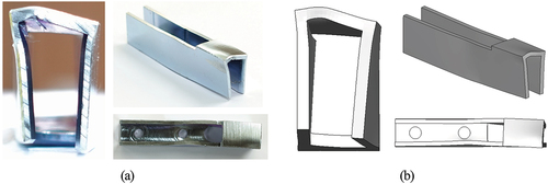
Figure 12. Deformation shape of the guide shoe after impact: (a) Experiment and (b) Simulation.
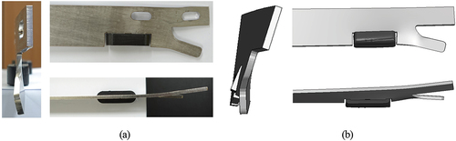
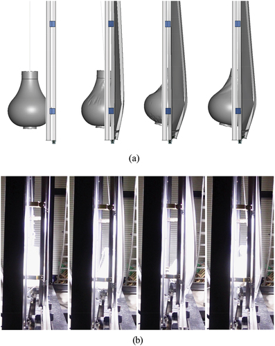
shows the numerically simulated and experimentally observed deformation behaviors in scenario B1. These two results are similar. Furthermore, the guide shoe has not been detached from the stopper even with a 2,000 J impact energy as expected in the simulation.
Figure 13. Comparison of the deformation behavior in impact scenario B1: (a) Numerical simulation and (b) Experiment.
4.3. Effect of the hook-type guide shoe
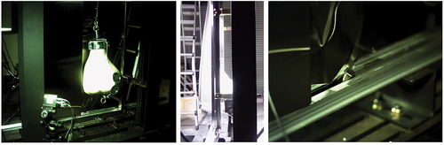
The test results of scenarios A1 and A3 were compared, as shown in . The same 1,000 J collision energy was applied to the door without a side hook. After carrying out impact tests with both flat- and hook-type guide shoes, the results were compared. shows the deformation behavior in impact scenario A1 with the flat-type guide shoes, and shows the deformation behavior in impact scenario A3 with the hook-type guide shoes. Although the same energy was applied, it was found that the guide shoe detached from the stopper when the flat-type guide shoe was used, whereas the guide shoe did not detach from the stopper with the hook-type. This is because the mechanism of physically induced interlocking by an actual hook is more efficient than the interlocking caused by simple friction between the guide shoe and stopper.
Figure 14. Deformation behavior in the impact scenario with flat-type guide shoes.
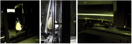
Figure 15. Deformation behavior in the impact scenario with hook-type guide shoes.
4.4. Impact test with an electric wheelchair
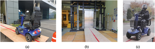
As a final verification of the safety retainers developed based on the collision test research with an impactor, an impact test was conducted using an electric wheelchair. It was assumed that an electric wheelchair was more likely to collide with the center of both doors, considering the size of conventional elevator doors and electric wheelchairs. As tested in scenario D1, the safety retainers did not detach when facing a 2,000 J impact energy, as both doors absorbed the energy that hit the two doors simultaneously. When applying a flat-type guide shoe, the mass of the electric wheelchair was 125 kg, and that of the person in the vehicle was 75 kg. When colliding at a speed of 13 km/h, approximately 1,300 J of the impact energy was generated. demonstrates the preparation of the impact test and the electric wheelchair used in the test.
Figure 16. Setup for the impact test with an electric wheelchair: (a) Electric wheelchair, (b) Impact test equipment, and (c) Electric wheelchair with a driver.
shows the behavior of the electric wheelchair immediately after collision in the impact test. Immediately after the impact, the vehicle and rider’s body move forward, and the front wheels are lifted while rotating until the braking system starts to work. Given that the braking system does not activate instantly, it is highly likely that a fall accident will occur if the door safety retainers are not properly installed. demonstrates the deformed shape of the door, guide shoe, and stopper after collision. Because both doors simultaneously absorb energy, the door deformation is not significant, and the safety retainers work perfectly without detachment.
Figure 17. Behavior of the impact test with an electric wheelchair.
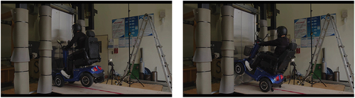
Figure 18. Deformed shape of each part after the impact test: (a) Door, (b) Guide shoe, and (c) Stopper.
5. Conclusion
In this study, elevator landing door safety retainers capable of withstanding 1,000 J were developed to prevent elevator landing door fall accidents of electric wheelchairs. The results were predicted through crash analysis simulations for various scenarios and were experimentally verified. The key conclusions of this study are as follows:
Crash analysis simulations were conducted after building scenarios that are not stated in the current regulations, considering the behavior of colliding electric wheelchairs into elevator landing doors.
It was found that different results were generated according to the shape of the guide shoe, and the hook-type demonstrated higher reliability than the flat-type. It is also confirmed that the side hook plays a critical role in withstanding a 1,000 J impact energy, and even a 2,000 J collision energy is absorbed when hitting the center of both doors.
Crash analysis simulations were verified by conducting actual tests on various established scenarios. A high conformity between the crash analysis simulations and test results was observed.
As a final confirmation, the reliability of the developed landing door safety retainers was verified with an impact test where a rider on an electric wheelchair collided with an impact energy of 1,300 J.
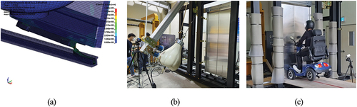
The main conclusions above are shown in . Landing door safety retainers based on the current regulations are unable to prevent fall accidents of electric wheelchairs. Therefore, the reliability of door safety retainers can be secured by conducting tests based on more feasible proposed scenarios. The conclusions of this study can provide basic data to improve regulations for preventing fall accidents of electric wheelchairs in elevator landing doors.
Figure 19. Conclusions of this study: (a) Reliable crash analysis simulation, (b) Verification using impactor test, and (c) Final verification using wheelchair test..
Disclosure statement
No potential conflict of interest was reported by the author(s).
Additional information
Funding
References
- LSTC, LS-DYNA Theory Manual. 2015. Michigan: Livermore Software Technology Corporation.
- ESEMS Website. Door Safety Retainers (Accessed January 10, 2023), http://esems.kr/sub03_01_01.php.
- AHN, S., H.-S. Jung, and J.-S. Kim. 2022. “Crash Analysis of Elevator Door Safety Retainers.” Journal of the Korea Academia-Industrial Cooperation Society 23 (1): 456–461. https://doi.org/10.5762/KAIS.2022.23.1.456.
- ASME 17.1. 2016. Safety Code for Elevators and Escalators: Includes Requirements for Elevators, Escalators, Dumbwaiters, Moving Walks, Material Lifts, and Dumbwaiters with Automatic Transfer Devices.
- BS EN 81-20. 2014. Safety Rules for the Construction and Installation of Lifts - Lifts for the Transport of Persons and Goods, Part 20: Passenger and Goods Passenger Lifts.
- BS EN 81-50. 2014. Safety Rules for the Construction and Installation of Lifts - Examinations and Tests - Part 50: Design Rules, Calculations, examinations and tests of lift components.
- CAO, X.-Q., F. Xiao, X.-Y. Zou, Y.-Q. Wang, Z.-X. Zhang, Z.-W. Lyu, J. Wang, G. Zhou, and X.-J. Lyu. 2022. “Synthesis of Cetylpyridinium Chloride/keggin-Al 30 Modified Montmorillonite: Experimental and Molecular Simulation Investigation.” Advanced Composites and Hybrid Materials 5 (1): 278–203. https://doi.org/10.1007/s42114-021-00339-5.
- CHEN, W., Y. Zhao, S. Yang, D. Zhang, and H. Hou. 2021. “Three-Dimensional Phase-Field Simulations of the Influence of Diffusion Interface Width on Dendritic Growth of Fe-0.5 Wt.% C Alloy.” Advanced Composites and Hybrid Materials 4 (2): 371–378. https://doi.org/10.1007/s42114-021-00215-2.
- EQI, M., C. Shi, J. Xie, F. Kang, H. Qi, X. Tan, Z. Huang, J. Liu, and J. Guo. 2023. “Synergetic Effect of Ni-Au Bimetal Nanoparticles on Urchin-Like TiO2 for Hydrogen and Arabinose Co-Production by Glucose Photoreforming.” Advanced Composites and Hybrid Materials 6 (1): 5. https://doi.org/10.1007/s42114-022-00580-6.
- Fei, H. U., L. Wang, Y. Liu, M. M. Hessien, I. H. E. Azab, S. Jing, A. Y. Elnaggar, S. M. El-Bahy, M. Huang, and R. Zhang. 2022. “Molecular Dynamics Simulation and Experimental Study of 3, 5-Difluoro-2, 4, 6-Trinitroanisole/2, 4, 6, 8, 10, 12-Hexanitrohexaazaisowurtzitane Mixed Components.” Advanced Composites and Hybrid Materials 5 (2): 1307–1318. https://doi.org/10.1007/s42114-022-00506-2.
- GAO, F., Y. Liu, C. Jiao, S. M. El‐Bahy, Q. Shao, Z. M. El‐Bahy, H. Li, et al. 2023. “Fluorine‐Phosphate Copolymerization Waterborne Acrylic Resin Coating with Enhanced Anticorrosive Performance.” Journal of Polymer Science. https://doi.org/10.1002/pol.20230108.
- GIAGOPOULOS, D., I. CHATZIPARASIDIS, and N. S. SAPIDIS. 2018. “Dynamic and Structural Integrity Analysis of a Complete Elevator System Through a Mixed Computational-Experimental Finite Element Methodology.” Engineering Structures 160:473–487. https://doi.org/10.1016/j.engstruct.2018.01.018.
- HE, B., Y. Xu, J. Zhu, and X. Zhang. 2021. “Effects of the Doping Density of Charge-Transporting Layers on Regular and Inverted Perovskite Solar Cells: Numerical Simulations.” Advanced Composites and Hybrid Materials 4 (4): 1146–1154. https://doi.org/10.1007/s42114-021-00343-9.
- HUANG, J., X. LU, and X. ZHANG. 2022. “Transient Computational Fluid Dynamics Simulation of Pulse Feed in Vacuum Membrane Distillation Process.” Advanced Composites and Hybrid Materials 5 (3): 2515–2526. https://doi.org/10.1007/s42114-022-00502-6.
- HUBALOVSKY, S. 2013. “Modeling, Simulation and Visualization of Static Mechanical Properties of Frame of Elevator Cab.” International Journal of Mathematical Models and Methods in Applied Sciences 7 (6): 666–675.
- Jia, Y. A. N., Y. Niu, C. Wu, Z. Shi, P. Zhao, N. Naik, X. Mai, et al. 2021. “Antifungal Effect of Seven Essential Oils on Bamboo.” Advanced Composites and Hybrid Materials 4 (3): 552–561. https://doi.org/10.1007/s42114-021-00251-y.
- LI, L., M. He, Y. Feng, H. Wei, X. You, H. Yu, Q. Wang, et al. 2021. “Adsorption of Xanthate from Aqueous Solution by Multilayer Graphene Oxide: An Experimental and Molecular Dynamics Simulation Study.” Advanced Composites and Hybrid Materials 4 (3): 725–732. https://doi.org/10.1007/s42114-021-00310-4.
- Lu-Xi, L. U., X.-L. Wang, S.-L. Li, Y. Tang, and X.-M. Mai. 2023. “Thermal Performance of Lonicera Rupicola Grass as a Building Insulation Composite Material.” Advanced Composites and Hybrid Materials 6 (1): 8. https://doi.org/10.1007/s42114-022-00578-0.
- ONUR, Y. A., and C. E. İ̇mrak. 2012. “Reliability Analysis of Elevator Car Frame Using Analytical and Finite Element Methods.” Building Services Engineering Research and Technology 33 (3): 293–305. https://doi.org/10.1177/0143624411413168.
- TONG, Y., L. Wang, B. Wang, Y. Hu, Z. Cai, J. Ren, J. Liu, et al. 2023. “Microstructure and Mechanical Behavior of Carbon Fiber Reinforced Carbon, Silicon Carbide, and Copper Alloy Hybrid Composite Fabricated by Cu-Si Alloy Melt Infiltration.” Advanced Composites and Hybrid Materials 6 (1): 25. https://doi.org/10.1007/s42114-022-00612-1.
- WU, N., B. Zhao, X. Chen, C. Hou, M. Huang, A. Alhadhrami, G. A. M. Mersal, M. M. Ibrahim, and J. Tian. 2022. “Dielectric Properties and Electromagnetic Simulation of Molybdenum Disulfide and Ferric Oxide-Modified Ti3C2TX MXene Hetero-Structure for Potential Microwave Absorption.” Advanced Composites and Hybrid Materials 5 (2): 1548–1556. https://doi.org/10.1007/s42114-022-00490-7.
- Xianmin, M. A. I., J. Mai, H. Liu, Z. Liu, R. Wang, N. Wang, X. Li, et al. 2021. “Advanced Bamboo Composite Materials with High-Efficiency and Long-Term Anti-Microbial Fouling Performance.” Advanced Composites and Hybrid Materials 5 (2): 1–8. https://doi.org/10.1007/s42114-021-00380-4.
- ZHANG, H., J. Mai, S. Li, J. T. Althakafy, H. Liu, A. K. Alanazi, S. M. El-Bahy, et al. 2022. “Multi-Functional Phase Change Materials with Anti-Liquid Leakage, Shape Memory, Switchable Optical Transparency and Thermal Energy Storage.” Advanced Composites and Hybrid Materials 5 (3): 2042–2050. https://doi.org/10.1007/s42114-022-00540-0.
- ZHANG, H., J. Zhong, Z. Liu, J. Mai, H. Liu, and X. Mai. 2021. “Dyed Bamboo Composite Materials with Excellent Anti-Microbial Corrosion.” Advanced Composites and Hybrid Materials 4 (2): 294–305. https://doi.org/10.1007/s42114-020-00196-8.
- ZHAO, Y., K. Liu, H. Zhang, X. Tian, Q. Jiang, V. Murugadoss, H. Hou, et al. 2022. “Dislocation Motion in Plastic Deformation of Nano Polycrystalline Metal Materials: A Phase Field Crystal Method Study.” Advanced Composites and Hybrid Materials 5 (3): 2546–2556. https://doi.org/10.1007/s42114-022-00522-2.
- ZHAO, Z., P. Liu, H. Dang, Y. Chen, C. Zhang, and A. Pagani. 2022. “Understanding the Critical Role of Boundary Conditions in Meso-Scale Finite Element Simulation of Braided Composites.” Advanced Composites and Hybrid Materials 5 (1): 39–49. https://doi.org/10.1007/s42114-021-00284-3.
- ZHIGUO, M., S. Xianzhang, H. Yulong, Z. Jun, H. Ming, L. Yongzhi, L. Chuntai, et al. 2022. “Co-Simulation Technology of Mold Flow and Structure for Injection Molding Reinforced Thermoplastic Composite (FRT) Parts.” Advanced Composites and Hybrid Materials 5 (2): 960–972. https://doi.org/10.1007/s42114-021-00407-w.