
 ?Mathematical formulae have been encoded as MathML and are displayed in this HTML version using MathJax in order to improve their display. Uncheck the box to turn MathJax off. This feature requires Javascript. Click on a formula to zoom.
ABSTRACT
STFE(structural, transparent, fluorinated, envelope) membrane material is a new type of transparent architecture membrane material. Compared with general architecture membrane materials, which have the disadvantage of cannot balance strength and transparency, STFE has both high transparency and certain tensile strength. In this study, tensile strength tests were conducted on this new type of membrane material, and data obtained from different test methods, such as clamping test, winding test, and dumbbell-shaped test, were compared, and the mechanism for the differences was analyzed. The results showed that the winding-type test with smooth surface contact yielded the highest and most accurate strength data, clamping tests due to the tendency of the specimen to slip out of the clamping end, dumbbell tests due to the stress concentration effect, and winding tests with rough surface contact due to material damage caused by pressure, all reduce the measured tensile strength values. The measured tensile strength of STFE membrane material was 4241N/5 cm in the warp direction and 4335N/5 cm in the weft direction. This indicates that STFE membrane material has sufficient strength to be used in tensile membrane structures.
1. Introduction
Architecture membrane material is an important and common type of building material and the main component of membrane structure buildings. Since the 1950s, various membrane structure buildings have emerged, and the application of membrane materials in buildings has become increasingly widespread (Dinh Citation2016; Forster and Mollaert Citation2004; Llorens Citation2015; Otto Citation1973; Zhang Citation2019). Membrane materials can be used as the external enclosure of large buildings, such as the roof of sports stadiums, the ceiling of transportation facilities, the curtain wall of public buildings, etc. They can also be used as the main component of landscape architecture, such as tents or horn-shaped architectural pieces, various landscape pavilions, and so on. The characteristics of building membrane materials are lightweight, high strength, easy to tension during construction, good plasticity of shape, and ability to endow buildings with lightweight and varied shapes. Moreover, the construction process does not produce a large amount of construction waste, which conforms to the concept of green and low-carbon environmental protection.
The development of membrane structure architecture is inseparable from the innovation of architecture membrane materials (Zhang et al. Citation2018). Currently, the main forms of membrane structure architecture include tensioned membrane structures, skeleton supported membrane structures, cable supported membrane structures, and inflated membrane structures, among which, inflated membrane structures are divided into different types such as air supported, air rib, and cushion membrane structures. The commonly seen building membrane materials on the market are mainly divided into two categories: coated fabric membrane materials and polymer membrane materials. Coated fabric membrane materials are made by weaving high-strength polyester or glass fibers into a base cloth, and then covering it with a polymer protective coating. Polymer membrane materials are generally made by directly extruding one or more polymers to a certain thickness. Different production processes give the membrane materials different physical properties: coated fabric membrane materials mainly resist external force with fiber strength, so it has high tensile strength and tear strength, but the multilayer structure of fiber base cloth + coating + surface layer makes it thick (generally 0.3–1.5 mm), and can only transmit light to a certain extent, without transparency (Wang Citation2010; Yu Citation2020; Zhang et al. Citation2014, Citation2019; Zhou Citation2019); polymer membrane materials have a single composition and thinner texture (generally 0.05–0.3 mm), with high light transmittance and transparency, which means you can see the opposite scenery through the material, but due to their simple structure and thin thickness, the strength of these membrane materials is relatively lower than that of fabric membrane materials (Charbonneau, Polak, and Penlidis Citation2014; Hu et al. Citation2015; Wu, Mu, and Liu Citation2008).
Different membrane materials are suitable for different membrane structures. Coated fabric membrane materials, due to their high strength and excellent mechanical properties, can be used in various large span tensile, skeleton, and air supported membrane structures. One well-known example is the Shanghai Stadium (as shown in ). However, these materials are generally white and opaque, and their external appearance is relatively simple, making it difficult to meet the transparency requirements of some buildings. Polymer membrane materials have a highly transparent appearance and can be used to achieve a bright and transparent effect on some building facades. Their higher natural light utilization rate also makes buildings more energy-efficient. One example of such materials is the Eden Project greenhouse in the UK (as shown in ). However, these materials have too low strength and modulus of elasticity and cannot be used in large-span tensile membrane structures or air supported membrane structures. They can often only be used as accessories to building facades in the form of air cushions or air balloons. Currently, tempered glass is mainly used for various buildings with transparent facades or roofs, especially in high-rise office buildings, greenhouse gardens, airports, train stations, and other buildings. However, tempered glass has disadvantages such as heavy weight, difficulty in fitting curved surfaces with its hard texture, complex waterproofing joint, and especially the certain safety risk of self-explosion when subjected to extreme temperature changes, which brings sharp fragments that can cause injuries. Additionally, for these large-span light-weight structures, they are sensitive to vibrations, the dynamic problem of this structure under different hazards such as wind and earthquake is critical (Wang et al. Citation2020, Citation2022; Wang, Shi, and Zhou Citation2022), while tuned mass damper is a popular vibration absorber used generally in rigid structures (Wang et al. Citation2023; Wang, Zhou, and Shi Citation2023a, Citation2023b), its potential applications in flexible structures needs to be investigated in the future (Wang et al. Citation2020, Citation2021, Citation2023).
Figure 1. The coated fabric membrane structure- Shanghai Stadium.
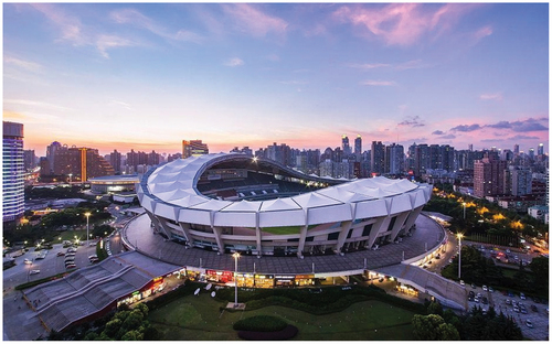
Figure 2. The polymer membrane structure - Eden Project greenhouse.

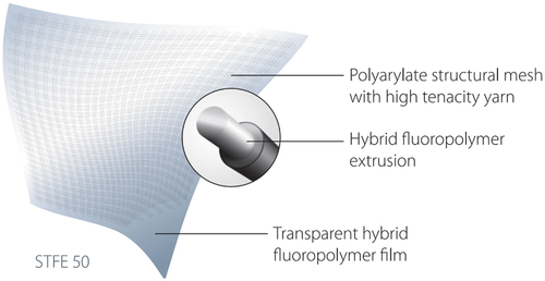
In order to expand the application of membrane materials in large-span transparent tensile membrane structures and various building curtain walls, Serge Ferrari Co., Ltd has developed and produced a new type of architectural membrane material named STFE-50. “S” stands for structural, “T” stands for transparent, “F” stands for fluorinated, “E” stands for envelope, and “50” represents its light transmittance is about 50%. The basic composition of the STFE membrane material is shown in . This material can be regarded as a fiber-reinforced composite polymer material. In the composition of the material, the thin film portion is a fluorinated polymer similar to the ETFE membrane, and the reinforced fiber is a high-strength white fluoropolymer yarn, which is coated with a black protective layer on the outside of the yarn. The material mainly relies on the structural mesh to bear the tension load weaved with the yarn, and the transparent hybrid fluoropolymer film plays the role of protection for the mesh. The yarn mesh and the transparent membrane are bonded together with glues, and the bonding strength is above 18.5 meters of water column, which is sufficient to ensure that the two materials do not peel off.
Figure 3. The basic composition of the STFE membrane material.
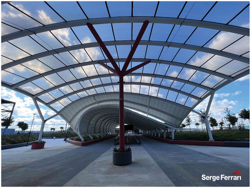
The transparency of STFE membrane material comes from the sparse arrangement of its polymer fibers, as shown in . The fibers are interwoven along the warp and weft directions, with three fibers in each group and a relatively long distance between adjacent groups of fibers, approximately 8.5 mm. Within each group, the distance between fibers is about 2 mm, and the diameter of a fiber is about 1 mm. When light passes through the material, some of it is blocked by the black fibers, while the rest can directly penetrate the transparent film and enter the interior space. Through a simple projection calculation, the light transmission area of the membrane material is slightly more than 50%, resulting in a light transmittance of about 50%. The arrangement of fibers in STFE membrane material is determined by the high strength of the polymer fibers, which are stronger than general polymer or glass fibers. Therefore, sufficient overall material strength can be achieved with a relatively small number of fibers. In addition, the transparency of STFE membrane material has certain limitations. When viewed up close, the fibers in the material are clearly visible, but when viewed from a distance of 5–10 meters or more, the fibers become basically invisible, and the overall appearance of the material is similar to that of a semi-transparent material. shows the application of the STFE material in the pedestrian walkway of the Istanbul Airport-Metro pedestrian road cover, where the stretched STFE membrane structure presents a lightly blurry effect (Istanbul Airport – Metro Pedestrian Road cover in STFE Citation2023).
Figure 4. The sparse arrangement of STFE membrane fibers.
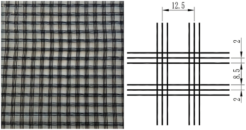
Figure 5. The blurry effect of STFE membrane in structures.
For this new type of architecture membrane material to be applied in the design of membrane structure buildings, its mechanical parameters must first be determined, among which tensile strength is a particularly distinguishing aspect of this material from transparent polymer membranes and requires precise measurement. There have been many related experiments on the tensile strength of coated fabric membranes and polymer membranes, including clamp tests, dumbbell-shaped tests, and winding tests. However, the material composition of STFE membrane material is different from these two general membrane materials, so it is necessary to compare the results of different tests and study which test scheme yields data that is closer to the material’s true mechanical properties. This paper tests the tensile strength of STFE membrane material using the test methods mentioned above, compares the test results, analyzes how the result data is affected by the test scheme, and determines the best test scheme for testing the tensile strength of STFE membrane material.
2. Materials and methods
In testing standards around the world, there are different requirements for the tensile strength testing of architecture membrane materials, and generally, the testing methods and requirements for coated fabric membranes and polymer membranes are also different (Li, Zhang, and Xue Citation2021; Standard for inspection of membrane structures: DG/TJ08–Citation2020; Xu et al. Citation2022). For coated fabric membranes, there are two methods for testing strength: uniaxial and biaxial (Xu et al. Citation2019; Xu, Zhang, and Xue Citation2017). The biaxial test is closer to the stress state of the material in the structure, but the test is prone to failure at the cutting edge of the specimen, and the strength measurement may be affected by specimen processing (Shi et al. Citation2019; Zhang and Zhang Citation2013). The uniaxial test is the more widely recognized strength testing method for coated fabric membranes, including clamping and winding test, and generally, membrane materials with rougher surfaces and higher friction coefficients are tested with the clamping method, such as PVC and PVDF membrane materials, while those with smoother surfaces and lower friction coefficients are tested with the winding method, such as PTFE membrane materials. For ETFE membrane materials, according to standard requirements (Standard for inspection of membrane structures: DG/TJ08–Citation2020), most use the dumbbell-shaped test method, while some use the rectangular strip test method with equal width and length.
This article mainly refers to the existing testing standards for the tensile strength of coated fabric membrane material, and designs uniaxial clamping and winding tests. At the same time, referring to the testing methods of polymer film materials, two specifications of dumbbell-shaped tests are designed. The specific test plans are as follows.
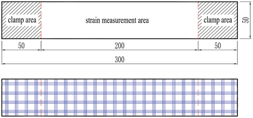
The uniaxial clamping test for STFE membrane material uses a rectangular shaped specimen with dimensions specified in the standard, which is 300 ± 1.0 mm in length and 50 ± 0.5 mm in width. The specimen has two clamping ends of 50 mm in length, which are fixed on the clamping fixture by frictional force. The middle section of the specimen is a 200 mm long strain measurement area, which is used to measure and calculate the material’s elongation at break. Coincidentally, one basic unit of the STFE membrane material (as shown in ), which is a pattern repeatedly arranged on the film surface, has a size of about 12.5 mm square. Therefore, within the 50 mm width range, four sets of fibers can be arranged, which ensures that the fiber density within the specimen width range (50 mm) is basically consistent with the fiber density within the entire membrane material width range, making the strength measurement representative of the overall material. Similarly, it is necessary to arrange the fiber distribution reasonably in the length direction. When cutting the specimen from the membrane, it should be ensured that the specimen is not cut in the middle of a set of fibers so that each set of fibers is evenly distributed in the middle of the specimen in the length direction. The schematic diagram of the specimen cutting is shown in , where the blue line represents the position of the fiber.
Figure 6. The dimension of the clamping test specimen.
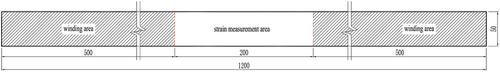
The winding test is a type of test method recognized by the testing organization as relatively accurate for determining the tensile strength of materials, which has good applicability for various types of coated fabric membranes. Compared to the clamping test which can be easily for the sliding out type destruction from the fixture, the winding test can ensure that the specimen is fractured in the middle position of the strain measurement area of the specimen, making the data obtained closer to the true strength of the material. The test specimen for the winding test is shown in . The specimen width is also 50 ± 0.5 mm, the length is 1200 mm, and the middle is a 200 mm strain measurement area, with a 500 mm winding area on each side. The principle of the winding test is to repeatedly wind and fix the winding area of the specimen on the winding fixture, with the specimen pressing against the cylindrical surface of the fixture and the specimen itself. During the stretching process, as the tensile force increases, the pressure and friction between these contact surfaces also increase. Therefore, the friction force of the fixture can be kept matching the stress of the specimen throughout the test, and the specimen will not slide off the fixture. It is also for this reason that the winding test requires a longer winding and fixing area, consequently, the winding test specimen consumes four times the amount of material compared to the clamping test specimen. Like the clamping test, the winding test also needs to ensure that there are four groups of fibers within the width and avoid cutting in the middle of a fiber group during specimen cutting.
Figure 7. The dimension of the winding test specimen.
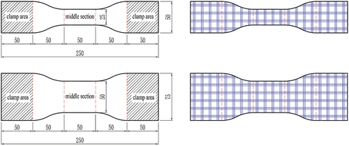
Dumbbell-shaped test is a special type of clamping test method, commonly used for strength testing of polymer membranes such as ETFE, and sometimes used for coated fabric membranes. The dumbbell-shaped test is mainly designed to address the issue of materials with smooth surfaces slipping out of the fixture during loading. The specimen is processed into a dumbbell shape with wider clamping ends and a narrower middle section to ensure that the fixture can provide sufficient frictional force, and that the failure mode of the specimen is breaking in the middle. The dumbbell-shaped test specimen for ETFE film is narrow, with a middle section only 6 mm wide. When designing the dumbbell-shaped test for STFE film, it is necessary to consider that the fracture location in the middle of the specimen must contain fibers to obtain the strength measurement. Therefore, two different sizes of test specimens were cut. The narrower one has an end width of 50 mm, containing four groups of fibers, and a middle section width of 25 ± 0.5 mm, containing two groups of fibers; the wider one has an end width of 75 mm, containing six groups of fibers, and a middle section width of 50 ± 0.5 mm, containing four groups of fibers. The dimensions of the two dumbbell-shaped test specimens are shown in , with a length of 50 mm for the clamping ends, which are clamped in the fixture, and a middle length of 50 mm, which is designed to fail, with a certain arc transition between the clamping ends and the middle section.
Figure 8. The dimension of the dumbbell-shaped test specimen.
The uniaxial tensile test is conducted on an electronic universal testing machine, which can perform displacement-based or load-based constant speed stretching. Different fixtures can be installed on the testing machine to apply loads to different specimens. Clamping fixtures are clamped on the specimen by rotate the screws, and in order to increase the frictional force, the clamping surface is often made into a wavy or serrated shape. The winding fixture gradually generates frictional force during the stretching process. The winding fixture in this paper has two cylindrical winding ends. The outer cylinder generates a frictional force on the surface of the specimen, and the inner cylinder changes the direction of the specimen and acts as a fixed support.
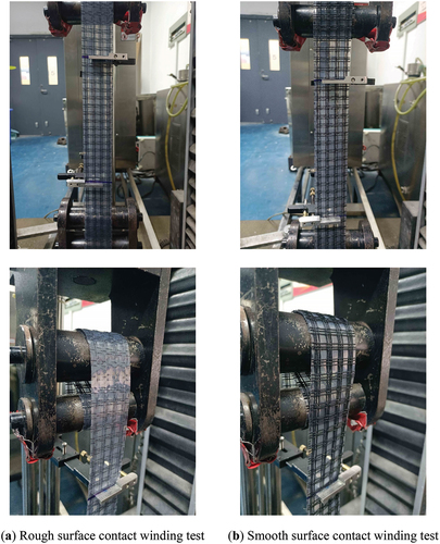
The testing device is shown in . depicts a typical uniaxial clamping test, with the specimen fixed on a wavy clamping fixture. shows two dumbbell-shaped specimens with different widths, clamped separately on wavy and serrated fixtures. illustrates the uniaxial winding test, which can be divided into two methods depending on the way friction is generated: the smooth surface winding test and the rough surface winding test. Due to the different properties of the two sides of the STFE membrane, the frictional performance they generate also differs. The side with fibers is very rough and is more likely to generate friction due to the effect of fibers pressing and resist the sliding against each other. The side with the polymer film is relatively smooth, and although it also has a surface with irregularities under pressure, the overall friction coefficient is much smaller than that of the fiber side.
Figure 9. The general clamping test device.
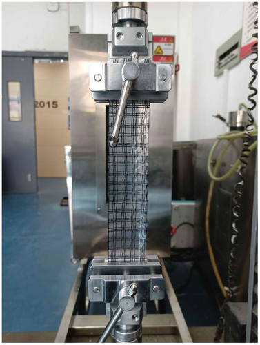
Figure 10. The dumbbell-shaped clamping test device.
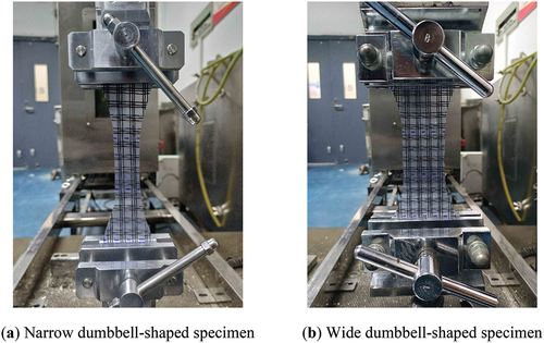
Figure 11. The winding test device.
In the test, the tensile force is measured by a load sensor connected to the machine via the fixture, and the method of displacement measurement depends on the test mode. For the clamping test, the displacement sensor of the machine can be used directly to measure the displacement of the fixture. For the winding test, as the specimen will undergo certain sliding displacement relative to the fixture due to generate frictional force, the displacement of the specimen must be measured using an extensometer. Two linear extensometers are fixed at the upper and lower clamping lines of the strain measurement section, and the stress-strain curve and fracture strain can be obtained by recording the relative displacement of the two extensometers during the stretching process and calculating, as shows.
The test is conducted at a temperature of (20 ± 2) ℃ and a relative humidity of (65 ± 4)%. The test is performed by displacement loading at a speed of 100 mm/min, which is according to DG/TJ08–2019–2019. For the aforementioned five test schemes (general clamping test, dumbbell-shaped test specimens with two fiber groups, dumbbell-shaped test specimens with four fiber groups, rough surface contact winding test, and smooth surface contact winding test), two types of specimens in the warp and weft directions are respectively cut and tested for each scheme. In each set of tests, five specimens are tested repeatedly to calculate the average value of their data.
3. Results and discussion
Through the various tests described above, data on the tensile strength, elongation at break, stress-strain curves, and other properties in both the warp and weft directions of the STFE membrane can be obtained. In this section, an analysis and discussion of these data will be presented.
3.1. Tensile strength
Tensile strength is the focus of this series of experiments and one of the most important parameters of STFE membrane. The tensile strength in the warp and weft directions measured by the above tests is shown in . It can be seen that the strength measured by different test schemes varies greatly, and there are also significant differences in the warp and weft strengths measured in a single test scheme. It is undeniable that the test results of STFE membrane data have certain discreteness due to various differences and uncertainties in the production process.
Table 1. The tensile strength of STFE membrane with different test methods (N/5 cm).
Comparing the tensile strength results from various tests, the data from the winding test is the highest, while the general clamping test yields lower results, and the strength results of the two types of dumbbell-shaped specimens are the lowest. On average, only the winding test with smooth surface contact is able to achieve tensile strength values above 4000N/5 cm for both the warp and weft directions.
3.1.1. Analysis of the general clamping test results
Firstly, analyze the results of the general clamping test. The reason for the lower results of the clamping test is that the main failure mode of this type of test is the slippage of the clamped end out of the fixture, rather than the fracture of the measuring area in the middle of the specimen. The mechanism of this type of failure is that the static friction provided by the fixture cannot resist the stress of the specimen, causing the specimen to be pulled out of the fixture. When the failure occurs, the middle of the specimen has not yet reached its strength, so the measured data is underestimated. In addition to the failure mode of specimen slippage, the clamping test also exhibits a failure mode where the fiber in the clamping area breaks and extends to the middle area of the specimen. This is because the clamping fixture applies a lot of pressure to the specimen, causing the warp and weft fibers to be tightly compressed. Some fibers are damaged under pressure and thus fail earlier than the middle area. shows photos of the failure mode of the clamping test specimen. It can be seen that whether it is failure due to slippage or damage caused by compression, the failure position of the specimen occurs in the clamping area In particular, in the position near the clamping line, a form of damage occurs in which the protective layer is neatly broken and the inner fibers are exposed by folding due to the damaging effect of the wavy fixture on the fibers. Therefore, the data of this type of test is underestimated and cannot be used as the measured value of the STFE membrane’s tensile strength.
Figure 12. The failure mode of the clamping test specimen.
The difference in failure mode also distinguishes the results of the general clamping test from those of other tests. The results of other tests show that the breaking force of the weft direction specimen is greater than that of the warp direction specimen, while only the general clamping test shows that the breaking force of the warp direction specimen is greater than that of the weft direction specimen. This result is due to the difference in the warp and weft direction caused during the production of STFE membrane material. During the production of the base fabric, the weft fibers are first stretched straight, and then the warp fibers are waved up and down through the weft fibers to form a mesh. Therefore, in the STFE film fabric, the weft fibers are relatively straight, while the warp fibers are more curved. When the failure mode is due to the fiber reaching the strength limit, the warp fibers must be straightened first and then loaded until they fracture, during which damage is caused by the resistance of the weft fibers. The weft fibers themselves are straight, and are less affected by the warp fibers during the loading process, so their breaking force is higher. However, when the failure mode is that the specimen slips out from the clamping fixture, the situation is just the opposite: the warp fibers are more curved, so they provide higher frictional force in the clamping area, while the straight weft fibers provide lower frictional force, leading to earlier slippage.
3.1.2. Analysis of the dumbbell-shaped clamping test results
The tensile strength obtained from the dumbbell-shaped test is the lowest among various tests, which is related to the shape of the specimen used in the dumbbell-shaped test. The dumbbell shape design ensures that the specimen breaks at the middle position, but at the same time, it causes uneven stress distribution, leading to premature failure of the specimen. The uneven stress distribution within the specimen is not only caused by the overall shape of being wide at both ends and narrow in the middle, but also by the sparse and grouped arrangement of fibers within the specimen, which makes the stress concentration effect of STFE membrane material more severe in the dumbbell-shaped test than in general woven membrane materials.
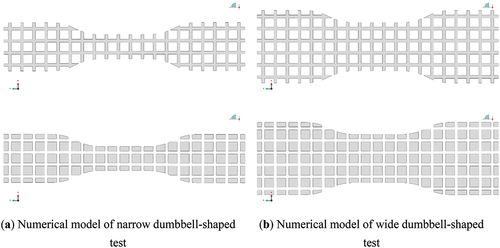
To investigate the stress concentration effect of dumbbell-shaped specimens, a numerical analysis model of this type of specimen was established in the general finite element software ABAQUS, and finite element simulation was carried out. As shown in , simulations were performed on both narrow and wide specimens. Certain simplifications were made during modeling, and three fibers in a group were merged into a single elongated strip, with a width of 3 mm and a thickness of 1 mm. The strips were woven into a mesh at the center position of the fibers, with mesh sizes consistent with those of STFE membrane material. The remaining transparent film pieces were modeled as various polygons of different sizes, which were connected to the main force resistance strip mesh, and deformed with the mesh, with a thickness of 0.25 mm. In the finite element calculation, because the main purpose of the finite element calculation is to examine the way of tension transmission between the groups of fibers and the stress concentration effect caused by them, so the results obtained by using a plane model can fully reflect these details of the examination, and the fibers and film are established as a plane model in the numerical calculation, and the fibers and the transparent diaphragm are modeled with shell elements. Tie constraints are used between the fiber element and the film element to bind the peripheral displacements of the film region with the fibers, so that the film region can follow the fiber region movement and deformation. In the calculation, the tensile force loading is used, and the boundary conditions are fixed by uniaxial tensile boundary fixed as the loading in the test, i.e., three-axis translational constraints are used at one end, and two-axis translational constraints are used at the other end except for the tensile direction.
Figure 13. The numerical model of the dumbbell-shaped test.
In finite element numerical simulations, the constitutive model for the fiber region is assumed to be an orthotropic mechanical model. The stress-strain relationships in the longitudinal and transverse directions are represented by Equation 1. The constitutive parameters for the material include the elastic modulus in the warp and weft directions (Ex, Ey) and the Poisson’s ratios in the warp and weft directions (νx, νy). Under the assumption of an orthotropic mechanical model, the overall elastic moduli and Poisson’s ratios of the material are calibrated through biaxial tests, in addition, the shear modulus is calibrated from a picture frame shearing experiment. Then, based on the proportion of fibers within the material width, the mechanical parameters of the fiber material can be approximately derived, as shown in . The portion of the film part of STFE membrane can provide very little resistance and its texture is similar to that of the ETFE polymer membrane, so the mechanical properties of the ETFE membrane was used as an approximate substitute in the numerical simulations, which the elastic modulus of 200kN/m and Poisson’s ratio of 0.3.
Table 2. The mechanical parameters of the fiber material.
In ideal conditions, stress should be uniformly transmitted from the clamped ends of the specimen to the narrower middle section, with each fiber experiencing equal stress. Assuming maximum stress of 4000N/5 cm for the specimen, the narrow specimen is subjected to a tension force of 2000N, while the wider specimen is subjected to a tension force of 4000N. Considering that fibers are the main load-bearing component, the proportion of tensile force borne by the thin film is small. For the narrow specimen, there are four groups of fibers in the clamping area, with a stress of:
2000N/(4 × 3 mm2) ≈ 167Mpa
There are two groups of fibers in the middle area, with a stress of:
2000N/(2 × 3 mm2) ≈ 333Mpa
For the wider specimen, there are six groups of fibers in the clamping area, with a stress of:
4000N/(6 × 3 mm2) ≈ 222Mpa
There are four groups of fibers in the middle area, with a stress of:
4000N/(4 × 3 mm2) ≈ 333Mpa
According to the above calculation, when we take the tensile strength of the specimen to be 4000N/5 cm, assuming that the tensile strength is all borne by the fiber and the stress is uniformly distributed in the cross-section, the fiber stress (in this model) of the two dumbbell-shaped specimens is about 333Mpa.
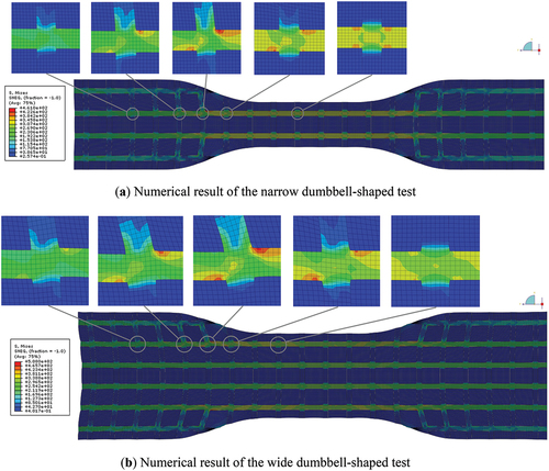
The Mises stress distribution of the dumbbell-shaped test simulated in ABAQUS is shown in . It can be seen that for both types of specimens, the stress is mainly borne by the fibers, and the stress level in the transparent film area is very low. In the wider clamping area at both ends, the stress of the fibers is lower. Comparatively, the stress of the fibers on the outer side is slightly lower than that of the directly connected fibers in the middle. In the narrower failure area in the middle, the stress of the fibers is higher than that at both ends, which is consistent with the design of the fibers to fracture in this area. In terms of the displacement of the entire specimen, the fibers on the outer sides of the throughout fibers mainly pulled the three sets of transverse fibers near the central area, and transmitted the tensile force to the throughout fibers in the middle through this pulling effect. The two groups of fibers on the outer side of the narrower specimen transmitted the tensile force to the two groups of fibers in the middle, and the stress of the two groups of fibers in the middle is basically the same. The two groups of fibers on the outer side of the wider specimen transmitted the tensile force to the two groups of fibers on the second outer side, and then indirectly to the two groups of fibers in the middle. Therefore, the stress of the two groups of fibers on the second outer side is slightly higher than that of the two groups of fibers in the middle, and the distribution of stress is uneven. High-stress zones and slightly lower stress zones can be clearly seen on the stripes.
Figure 14. The numerical result of the dumbbell-shaped test.
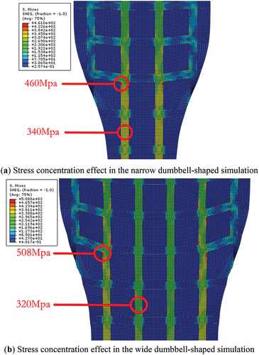
As shown before, the specimen wouldn’t be destroyed in the high stress zone of the central throughout the fiber, contrary to the experimental design. As shown in , the stress detail cloud map of the width transition zone of the specimen can be seen, and it can be seen that in the transition zone, due to the action of the fibers on both sides transferring tensile force to the middle fiber, the area of stress concentration appears at the intersection of the fiber mesh. By extracting the stress of the stress uniformity unit position and the stress concentration area in the model, we will find the stress concentration effect is very obvious. For narrow specimens, the uniform stress of their throughout fibers is about 340Mpa, but the highest stress at the stress concentration position reaches 460Mpa, and the stress concentration factor reaches 1.35. For wide specimens, the uniform stress of their throughout fibers is about 320Mpa, but the highest stress at the stress concentration location reaches 508Mpa, and the stress concentration factor reaches 1.59. When the tensile force is transmitted to the central area, the average stress is close to the ideal state calculated as 333Mpa, but in the local area connected to the outer fibers, the stress may be 30% or even 50% higher than the average stress. Therefore, during the tensile process of the test, these local areas may reach the failure stress before the average stress of the fiber reaches the failure stress, resulting in premature failure of the specimen.
Figure 15. The stress concentration effect in dumbbell-shaped numerical simulation.
The stress concentration factor of the dumbbell-shaped test can be calculated based on the test results. Assuming that the tensile strength of the STFE membrane material in the warp and weft directions is 4000N/5 cm, the stress concentration factor can be obtained by dividing 4000 by the average value of the dumbbell-shaped test results in . The stress concentration factors in the warp and weft directions of the narrow specimens are calculated to be 1.49 and 1.25, and those of the wide specimens are calculated to be 1.38 and 1.24. These values are close to the stress concentration factors obtained by numerical simulation. Therefore, if the existence of the stress concentration effect is taken into account, the failure strength of the STFE membrane material should be close to or exceed 4000N/5 cm.
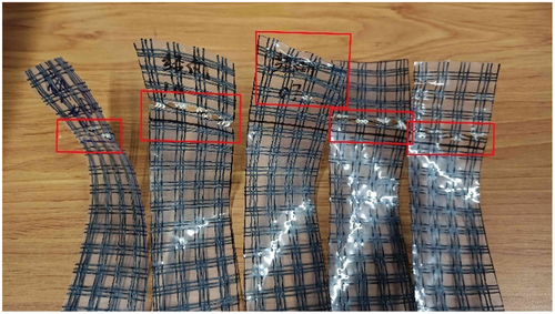
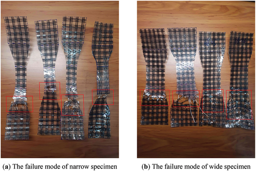
Obviously, this kind of stress concentration is a characteristic of the dumbbell-shaped test. For specimens with the same width, there is no process of tensile force transmission from the outer fibers, and the stress distribution will be relatively uniform, without such a big stress concentration factor. As can be seen from the failure mode of the dumbbell-shaped test shown in , the failure basically occurs in the transition zone from wide to narrow of the specimen, rather than at the narrowest position in the middle. This is consistent with the results of numerical simulation. It is easy to find that the tensile deformation of the fiber mesh and the shear fold of the transparent film sheet appeared in the destructive position of the dumbbell-shaped test, which reflects the stress transition and concentration phenomenon of the two sides of the fiber tensile force transfer to the middle fiber, which is in good conformity with the results of numerical simulation, and indicates that there are indeed some defects in the dumbbell-shaped test applied to the determination of tensile strength of the STFE membrane material.
Figure 16. The failure mode of the dumbbell-shaped specimen.
3.1.3. Analysis of the winding test results
Compared with other methods, the tensile strength data obtained from winding tests are the highest. This is because the winding test can cause the specimen to fail at the middle position without stress concentration effects, and the strength measured represents the state when uniform stress is transferred to the specimen to reach the failure point. However, there can be differences in the results obtained from winding tests depending on the specific test method used. Rough surface contact winding tests may result in lower strength values compared to smooth surface contact winding tests, and this can be analyzed by considering the impact of the winding process on the material fibers.
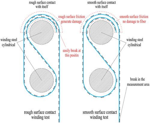
is a cross-sectional view of the upper fixture in the winding test, from which the difference between the two types of winding tests is clearly visible, and a complete understanding of the mechanism of frictional force generation in the winding test can be obtained. When the fixture moves upward, as shown in the red dashed box in , pressure and friction forces are generated between the specimen and itself in a semi-circular contact surface. This friction force can prevent the end of the specimen from sliding out of the gap below the contact surface, thus firmly fixing the specimen. During the loading process, the pressure and friction forces on the contact surface are constantly increasing. In order to maintain the changes in these interfacial forces, some sliding will occur on the contact surface. It is easy to see that when there is relative sliding between the upper and lower specimens, for rough surface contact tests, the transverse fibers in the cross-section will be squeezed against the loading direction fibers, which can easily cause damage to the fibers in the loading direction at that location. However, for smooth surface contact tests, there are two layers of transparent film between the fibers of the upper and lower specimens, which play a protective and lubricating role. The interaction between the two layers of fibers is very small and will not cause damage to the loading direction fibers.
Figure 17. The comparison of rough and smooth surface contact winding test.
In the experiment, it can also be observed that the two types of winding tests have different effects on the specimens. In the rough surface contact test, a “crackling” sound can be heard as a result of fiber compression and friction. During the test, some specimens experienced fiber damage, resulting in fractures at the friction location. As a result, the data obtained from these specimens were lower than those of other specimens, for example, as shown in , the value 5 in the warp direction and the value 3 in the weft direction. These unreasonable data reduced the average tensile strength. In contrast, in the smooth surface contact test, the relative sliding of the specimen was slower and more stable, and all specimens were fractured in the middle strain measurement zone. Therefore, the obtained data was more uniform, with both warp and weft tensile strength values above 4000N/5 cm. Moreover, despite the smooth surface contact, sufficient resistance was provided under pressure to prevent the specimen from slipping out of the fixture.
In a winding test, such differences in results appear for the first time. For generally coated fabric membranes, both sides are covered with smooth coatings, so no matter how they are winded, the results of the test are the same. However, the STFE membrane has different properties on both sides, with one side smooth and the other side rough. The side without surface protection is easily affected by the loading method during the test. Therefore, when conducting a winding tensile strength test, this should be taken into account as much as possible to avoid damage from the rough side being squeezed during the test.
3.2. Fracture elongation
The fracture elongation of STFE membrane material was determined using data from both general clamping tests and smooth surface contact winding tests. Since the data from the rough surface contact winding test was very close to that from the smooth contact winding test, no further comparison was made. The results of the fracture elongation test for the two aforementioned tests are shown in .
Table 3. The fracture elongation of STFE membrane with different test methods.
Obviously, the fracture elongation measured by the clamping test is significantly higher than that measured by the winding test, with average values in both the warp and weft directions exceeding 40% higher. In principle, the fracture elongation measured by the winding test is more accurate because linear extensometers are used to measure displacement in this type of test. The extensometers are clamped at both ends of the strain measurement area, and the displacement measured is the true displacement of the area. The reason why the clamping test measures much greater displacement than the winding test is that the displacement of the fixture is used as the displacement of the strain measurement segment, which leads to measurement errors. The slippage effect of STFE film material is not only manifested as the specimen slipping out of the fixture when it is broken, but also as a small sliding of the specimen during the test under load. Before failure, the relative sliding between the specimen and the fixture is approximately 2-6 mm. For some coated fabrics with fracture elongation of 10%-20%, this effect is not significant, but for STFE film materials with already low fracture elongation, such sliding will result in significant errors. Therefore, when measuring the fracture elongation of STFE membrane materials, the results of the winding test measured by the extensometer should be used as the standard.
3.3. Stress-strain curve
The stress-strain curve is a comprehensive reflection of the uniaxial tensile process. We have chosen the results of both the clamping test and the winding test to plot the stress-strain curve, as shown in , where the stress-strain curves in the warp and weft directions are separately drawn, reflecting the differences in the stress-strain relationships of STFE film materials in the warp and weft directions. By comparing the results of the tests in the warp and weft directions, it can be found that the stress-strain relationship in the warp direction is nonlinear, with the stress changing slowly at first and then quickly with the strain, and the curve approximating a quadratic function; while the stress-strain relationship in the weft direction is approximately linear, with the stress changing relatively uniformly with the strain, and the curve approximating a linear function. By comparing the results of the clamp test and the winding test, it can be found that regardless of whether it is in the warp or weft direction, the shapes of the curves in both tests are similar, but the proportions of the curves are different. The strain in the clamp test curve is much larger than that in the winding test curve at the same stress level, and the ultimate strain value at fracture is also greater than that in the winding test. On the other hand, at the same strain level, the stress in the winding test is much larger than the data from the clamp test, and the ultimate tensile strength at failure is also greater than that in the clamp test.
Figure 18. The stress-strain curve of clamping test and winding test.
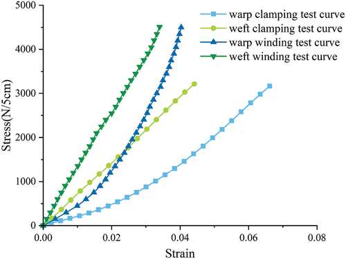
From the curves, it can also be seen that the difference between the results of the clamping test and the winding test does not appear suddenly at a certain strain or stress level, but gradually appears and changes with the loading process. This indicates that the sliding of the specimen in the clamping test also develops gradually rather than suddenly occurring at a certain degree of tension. This is also consistent with the mechanism of frictional force in the clamping test: as the load increases, the interfacial frictional force continuously increases and slowly undergoes tiny sliding. The above analysis shows that the stress-strain curve is indeed a good reflection of the mechanical differences in the testing methods.
3.4. Evaluation of STFE membrane tensile strength
According to the above analysis, the reasons for the lower tensile strength of the STFE membrane measured by various testing methods can be determined, and the conclusion that the smooth surface contact winding test results is the most accurate can be obtained. The obtained tensile strength of the STFE membrane in the warp and weft directions are 4241N/5 cm and 4335N/5 cm, respectively, which is strong enough compared to the strength of other general building membranes.
provides the tensile strength test results of some commonly used membrane materials, including both the warp and weft tensile strength and the elongation at break. From the table, it can be seen that the tensile strength of STFE membrane material is close to that of coated fabric membrane materials (Wang Citation2018; Xu Citation2018). In the tensile membrane structures where coated fabric membrane materials are used, the strength of STFE membrane material can also meet the requirements. The strength of ETFE membrane material (Wu et al. Citation2008) is much lower than that of STFE membrane material and coated fabric membrane materials (such as PVC and PTFE), and the strength calculated by width is only about 1/8 of that of STFE membrane material. In comparison, the higher strength of STFE membrane material and coated fabric membrane material can both be applied in large-span tensile membrane structures. The low strength of ETFE membrane material cannot guarantee its safety when used in tensile membrane structures.
Table 4. The results of different membrane materials in tensile test.
The difference in fracture elongation is more obvious than that in tensile strength. The warp and weft fracture elongation of STFE membrane is the smallest among all the membranes, indicating its highest elastic modulus and deformation resistance. PTFE membrane, due to the use of glass fiber, also has a relatively large elastic modulus, with a fracture elongation within 10%. PVC membrane, which uses polyester fibers, has a greater deformation compared to the two mentioned membranes, with an elongation at break reaching two digits. The elongation at break of ETFE film exceeds 300%, indicating that its texture is very soft and the deformation that occurs when stretched to break is more than twice the original length. The hardness of the material determines its suitability for different scenarios in construction. Materials that are too soft will experience excessive deformation when used for tension, which is unfavorable for maintaining structural shape and long term load bearing capacity.
4. Conclusions
As a summary of the analysis and discussion above, this article comes to the following conclusions:
In this paper, three types of tensile strength tests for STFE membrane materials were designed and conducted: the clamping test, the dumbbell shaped test with two different widths, and the winding test (categorized as smooth contact and rough contact). The results show that the winding test with smooth contact is the most accurate, and the measured tensile strength of STFE membrane shows that this type of membrane can be applied to large-span tensile membrane structures.
The mechanisms that produce differences in the results of different tests for determining tensile strength are compared; the clamping test will cause the specimen to slip out of the fixture, the dumbbell-shaped clamping test will produce stress concentrations on the specimen, and the winding test with rough contact will introduce damage at the contact location, these tests will result in lower strength results. The errors generated by these test methods are qualitatively analyzed and numerically simulated, and recommendations for test testing are made for STFE-like membrane materials.
Acknowledgements
The Serge Ferrari Shanghai Co., Ltd, is acknowledged for the materials donations.
Disclosure statement
No potential conflict of interest was reported by the authors.
Additional information
Funding
Notes on contributors
Ye Yuan
Ye Yuan, male, born in 1997, is currently a Ph.D. student in the College of civil engineering, Tongji University, China. His research area is cable and membrane structures.
Qilin Zhang
Qilin Zhang, male, born in 1962, is currently a Professor in the College of civil engineering, Tongji University, China. His research area is steel structures, aluminum structures, spatial structures, structural health monitoring, etc.
Xiaoqun Luo
Xiaoqun Luo, male, born in 1976, is currently an Associate Professor in the College of civil engineering, Tongji University, China. His research area is aluminum structures, cable and membrane structures, structural health monitoring, etc.
Yong Huang
Yong Huang, male, is currently the General manager of Serge Ferrari Shanghai Co., Ltd. His research area is membrane structures and membrane materials.
Ruijie Gu
Ruijie Gu, male, born in 1999, is currently a Master’s student in the College of civil engineering, Tongji University, China. His research area is membrane structures and membrane materials.
References
- Charbonneau, L., M. Polak, and A. Penlidis. 2014. “Mechanical Properties of ETFE Foils: Testing and Modelling.” Construction and Building Materials 60:63–72. https://doi.org/10.1016/j.conbuildmat.2014.02.048.
- Dinh, T. 2016. Numerical Analysis for Tension Membrane Structures and Multiscale Modeling for the Applied Coated Fabrics. Ghent, Belgium: Ghent University.
- Forster, B., and M. Mollaert. 2004. European Design Guide for Tensile Surface Structures. Brussels, Belgium: Tensinet.
- Hu, J., W. Chen, B. Zhao, and Wang K. 2015. “Uniaxial Tensile Mechanical Properties and Model Parameters Determination of Ethylene Tetrafluoroethylene (ETFE) Foils.” Construction and Building Materials 75:200–207. https://doi.org/10.1016/j.conbuildmat.2014.10.017.
- Istanbul Airport – Metro Pedestrian Road cover in STFE. Accessed March 26, 2023. https://www.sergeferrari.com/references/iga-istanbul-airport-metro-pedestrian-road-cover.
- Li, X., Z. Zhang, and S. Xue. 2021. “Summary of Experimental Research on Mechanical Properties of Architectural Membrane.” Building Structure 51 (Suppl.1): 588–593.
- Llorens, J. 2015. Fabric Structures in Architecture. Cambridge, The United Kingdom: Woodhead Publishing. ISBN 978-1782422334
- Otto, F. 1973. Tensile Structures: Design, Structure, and Calculation of Buildings of Cables, Nets, and Membranes. Cambridge, United States: The MIT Press. ISBN 978-0262150132
- Shi, T., W. Chen, C. Gao, J. Hu, B. Zhao, P. Wang, and M. Wang. 2019. “Biaxial Constitutive Relationship and Strength Criterion of Composite Fabric for Airship Structures.” Composite Structures 214:379–389. https://doi.org/10.1016/j.compstruct.2019.02.028.
- Standard for inspection of membrane structures: DG/TJ08-2019-2019. 2020. Shanghai: Tongji University Press.
- Wang, H. 2010. “Study on Evaluation Methods for Fiberglass Fabric Architectural Membranes.” Fiber Glass 235 (6): 18–25.
- Wang, T. 2018. Research on the Tensile and Tearing Properties of Architectural Coated Fabric, 18–27. Harbin, China: Harbin Institute of Technology.
- Wang, L., S. Nagarajaiah, W. Shi, and Zhou Y. 2020. “Study on Adaptive‐Passive Eddy Current Pendulum Tuned Mass Damper for Wind‐Induced Vibration Control.” The Structural Design of Tall & Special Buildings 29 (15): e1793. https://doi.org/10.1002/tal.1793.
- Wang, L., S. Nagarajaiah, W. Shi, and Zhou Y. 2021. “Semi-Active Control of Walking-Induced Vibrations in Bridges Using Adaptive Tuned Mass Damper Considering Human-Structure-Interaction.” Engineering Structures 244:112743. https://doi.org/10.1016/j.engstruct.2021.112743.
- Wang, L., S. Nagarajaiah, W. Shi, and Zhou Y. 2022. “Seismic Performance Improvement of Base-Isolated Structures Using a Semi-Active Tuned Mass Damper.” Engineering Structures 271:114963. https://doi.org/10.1016/j.engstruct.2022.114963.
- Wang, L., S. Nagarajaiah, Y. Zhou, and Shi W. 2023. “Experimental Study on Adaptive-Passive Tuned Mass Damper with Variable Stiffness for Vertical Human-Induced Vibration Control.” Engineering Structures 280:115714. https://doi.org/10.1016/j.engstruct.2023.115714.
- Wang, L., W. Shi, Q. Zhang, and Y. Zhou. 2020. “Study on Adaptive-Passive Multiple Tuned Mass Damper with Variable Mass for a Large-Span Floor Structure.” Engineering Structures 209:110010. https://doi.org/10.1016/j.engstruct.2019.110010.
- Wang, L., W. Shi, and Y. Zhou. 2022. “Adaptive-Passive Tuned Mass Damper for Structural Aseismic Protection Including Soil–Structure Interaction.” Soil Dynamics and Earthquake Engineering 158:107298. https://doi.org/10.1016/j.soildyn.2022.107298.
- Wang, L., Y. Zhou, S. Nagarajaiah, and W. Shi. 2023. “Bi-Directional Semi-Active Tuned Mass Damper for Torsional Asymmetric Structural Seismic Response Control.” Engineering Structures 293:116744. https://doi.org/10.1016/j.engstruct.2023.116744.
- Wang, L., Y. Zhou, and W. Shi. 2023a. “Seismic Control of a Smart Structure with Semiactive Tuned Mass Damper and Adaptive Stiffness Property.” Earthquake Engineering and Resilience 2 (1): 74–93. https://doi.org/10.1002/eer2.38.
- Wang, L., Y. Zhou, and W. Shi. 2023b. “Seismic Response Control of a Nonlinear Tall Building Under Mainshock-Aftershock Sequences Using Semi-Active Tuned Mass Damper.” International Journal of Structural Stability and Dynamics. https://doi.org/10.1142/S0219455423400278.
- Wu, M., J. Liu, T. Mu, and Zhang QL. 2008. “Uniaxial Tensile Properties of ETFE Foils.” Journal of Building Materials 48 (2): 241–247.
- Wu, M., T. Mu, and J. Liu. 2008. “Cycle Loading and Creep Tests of ETFE Foil.” Journal of Building Materials 11 (6): 690–694.
- Xu, J. 2018. Constitutive Model of Building Coated Fabrics, 77–94. Xuzhou, China: China University of Mining and Technology.
- Xu, J., Y. Zhang, M. Wu, and Zhao Y. 2019. “Experimental Analysis of Off-Axis Mechanical Behaviors of PVC Coated Fabrics Subjected to Cyclic Loading.” Polymer Testing 80:106090. https://doi.org/10.1016/j.polymertesting.2019.106090.
- Xu, J., Y. Zhang, and J. Xue. 2017. “Off-Axial Failure Analysis of Polytetrafluoroethylene-Coated Woven Glass Fibers Under Different Loading Rates.” Journal of Industrial Textiles 47 (3): 310–330. https://doi.org/10.1177/1528083716647198.
- Xu, J., Y. Zhang, Q. Yu, and L. Zhang. 2022. “Analysis and Design of Fabric Membrane Structures: A Systematic Review on Material and Structural Performance.” Thin-Walled Structures 170:108619. https://doi.org/10.1016/j.tws.2021.108619.
- Yu, Q. 2020. Mechanical Properties of Coated Fabric and Its Effect on Structure. Shanghai, China: Shanghai JiaoTong University.
- Zhang, Q. 2019. “Application Review and Future Development of Membrane Structures in China.” Building Structure 49 (19): 55–64. https://doi.org/10.19701/j.jzjg.2019.19.007.
- Zhang, Y., J. Xu, Y. Zhou, Zhang Q, and Wu F. 2019. “Central Tearing Behaviors of PVC Coated Fabrics with Initial Notch.” Composite Structures 208:618–633. https://doi.org/10.1016/j.compstruct.2018.09.104.
- Zhang, Y., and Q. Zhang. 2013. Mechanical Properties of Coated Fabric Architectural Membrane Materials. Xuzhou, China: China University of Mining and Technology Press.
- Zhang, Y., Q. Zhang, K. Lei, and K. Bei-Lei. 2014. “Experimental Analysis of Tensile Behaviors of Polytetrafluoroethylene-Coated Fabrics Subjected to Monotonous and Cyclic Loading.” Textile Research Journal 84 (3): 231–245. https://doi.org/10.1177/0040517513494259.
- Zhang, Y., Q. Zhang, Y. Xiao, and Lei K. 2018. “Advances in Mechanical Properties of Coated Fabrics in Civil Engineering.” Journal of Industrial Textiles 48 (1): 255–271. https://doi.org/10.1177/1528083716679159.
- Zhou, H. 2019. Study of Biaxial Warp Knitted Fabric Membrane Material Deformation and Tear Damage Mechanical Properties. Nanjing, China: Nanjing University Of Science And Technology.