
ABSTRACT
The number of visually impaired people continues to increase as the global population grows and ages, making the provision of textured guide blocks on the floor surfaces of public spaces increasingly critical. However, these blocks can also be obstacles for people with walking difficulties, wheelchairs, luggage, strollers, and other wheeled equipment. This study experimentally measured the vibration levels generated when passing a wheeled bogie over various convex curved guide block protrusions. The curved shape characteristics that induced less vibration in wheeled equipment while still effectively guiding the visually impaired were subsequently identified. The results indicated that curved shapes with widths greater than 13.5 mm and heights less than 5.0 mm exhibited reduced maximum vibration levels compared to the Japanese Industrial Standard (JIS) guide block. Even with a width and height matching those of the JIS block (27.0 mm and 5.0 mm, respectively), the curved shape induced less vibration. However, the maximum vibration level induced by the curved shape was greater than that induced by the JIS block when the height of the former was greater than 5.0 mm, regardless of width. Finally, the faster the bogie passing speed, the greater the maximum vibration level following an approximately linear relationship.
1. Introduction
The World Health Organization (Citation2022) has reported that at least 2.2 billion people worldwide suffer from myopia or hyperopia. Bourne et al. (Citation2017) noted that although the prevalence of blindness and visual impairment continues to decline, the number of people affected by visual impairment is substantially increasing owing to the growth and aging of the global population. The aging of the population is also expected to increase the number of people who use canes, assistive shopping carts, and wheelchairs owing to their declining physical functions. Indeed, the Cabinet Office of the Government of Japan (Citation2022) reported that approximately 30% of the Japanese population is 65 years or older (the aging rate), and that this percentage is expected to increase in the future.
According to the Japan Federation of the Visually Impaired (Citation2014), guide blocks for the visually impaired are blocks (or plates) provided on the ground or floor that have protrusions on their top surfaces that help to safely guide the visually impaired through the recognition of the tactile sensation on the soles of their feet. These guide blocks represent critical equipment enabling the visually impaired to move independently and safely to their destinations. Though guide blocks such as the JIS T 9251 are inexpensive and easy to install, they have been shown to act as barriers or trip hazards for pedestrians, present difficulties for baby strollers and wheeled suitcases on sidewalks, and hinder the movement of stretchers and medical equipment in welfare facilities and hospitals (Japan Federation of the Visually Impaired Citation2014; Yamada and Yamazaki Citation2019). Furthermore, large vibrations can be uncomfortable for wheelchair users and even potentially damage mobile electronic equipment in casters. Therefore, an effective convex protrusion shape for guiding the visually impaired is required that induces less vibration in wheeled equipment than the prismatic projections of JIS blocks.
This study accordingly investigated a curved guide block protrusion geometry to provide a more suitable traveling surface for wheeled equipment by investigating the vibrations generated when a wheeled device passed over a series of fabricated curved protrusion shapes. By analyzing the vibration levels and evaluating the vibration characteristics corresponding to the different curved protrusion surfaces, the most desirable protrusion shapes were identified considering the comfort and safety of all users. The results of this study can inform the development of smooth guide blocks that provide subtle unevenness to guide the visually impaired while ensuring the comfortable operation of wheeled equipment. The identified block geometry can thereby reduce the labor costs incurred by requiring receptionists and attendants to guide visually impaired and wheelchair-bound people through facilities and improve the experiences of all users of public spaces.
2. Literature review
There have been several published reviews of studies on guiding the visually impaired. Fernandes et al. (Citation2017) reviewed the assistive technologies proposed by researchers in recent years to address mobility limitations owing to visual impairment. They reported that the visually impaired often require not only information describing their location but also associations between their current location and the features present in the surrounding environment. El-Taher et al. (Citation2021) reported that a variety of assistive devices have been studied and developed over the past decade to help the visually impaired move more safely and independently.
Specific findings have been reported regarding the obstacles and problems faced by the visually impaired when moving: Pigeon et al. (Citation2019) stated that walking without vision imposes a cognitive load, and the more complex the environment, the greater this load; Riazi et al. (Citation2016) suggested that as sidewalks can be among the most dangerous places for the visually impaired, proper urban maintenance is beneficial; Park and Chowdhury (Citation2018) reported that the primary barriers hindering the movement of the visually impaired include inadequate information presentation and obstacles on sidewalks; and Low et al. (Citation2020) evaluated the travel experiences of visually impaired individuals in public transportation, reporting limited access to information, inconsistent infrastructure, and lack of staff support as their primary concerns. Furthermore, Tokuda (Citation2001) reported on specific barriers encountered by people with mobility difficulties, particularly the visually impaired and wheelchair users, highlighting sidewalk steps, obstacles on sidewalks, uneven sidewalks, steep slopes, and improperly laid guide blocks. These results all illustrate the need for pedestrian space improvement to accommodate a wide range of mobilities.
As a result, various studies have investigated the installation of guide blocks to help the visually impaired navigate pedestrian spaces. Tanaka and Iwata (Citation1997) stated that differences in facility planning and philosophies of guide block installation can have unintended effects on users. Indeed, Mizuno et al. (Citation2008) reported that warning blocks (dotted blocks) were often not installed at the intersections of guide blocks (linear blocks) or were improperly installed such that they impeded the movement of people in wheelchairs. Pembuain, Priyanto, and Suparma (Citation2020) stated that the primary problems associated with existing guide block installations included poor connectivity, unsafe routes, inconsistent installation, and sidewalk facilities that were unfriendly to the visually impaired. In addition, Padzi, Ibrahim, and Karim (Citation2013) stated that the arrangement of guide blocks and the user’s level of experience were frequently responsible for the deviation of the visually impaired from guide block pathways.
Other studies (Lu, Siu, and Xu Citation2008; Øvstedal, Lindland, and Lid Citation2005) investigated the practices and guidelines governing the installation of guide blocks for the visually impaired in different countries. The tactile walking surface indicator (TWSI), which was invented in Japan in 1965, was published as ISO 23599 in March 2012 to facilitate the independent mobility of the visually impaired (Fujisawa and Sueda Citation2012). The publication of an international standard for TWSIs is expected to promote the global use of guide blocks and contribute to the safety and convenience of the visually impaired in Japan (Ohno, Mizukami, and Tauchi Citation2014). Ma et al. (Citation2021) confirmed that guide blocks for the visually impaired can help them remain within straight crosswalks, avoid changes of direction, shorten crossing times, and improve the regularity and symmetry of their gait. However, various criticisms of TSWI design effectiveness have been frequently aired in the decades since they were widely implemented (Lu, Siu, and Xu Citation2008).
Studies have accordingly evaluated the effectiveness of different guide block shapes by conducting walking experiments using visually impaired subjects (Courtney and Chow Citation2000; Øvstedal, Lid, and Lindland Citation2005; Ranavolo et al. Citation2011). Suzuki et al. (Citation2001) reported that the height of the subject, their degree of visual impairment, and differences in test simulations affected the stride length and walking speed of visually impaired people when walking on guide blocks in everyday spaces. Pluijter et al. (Citation2015) stated that future guide block designs should focus on providing directional cues and a more stable surface.
Indeed, findings have been reported concerning the tactile and perceptual information required to guide the visually impaired. Takamiya and Hamada (Citation1998) found that the visually impaired confirm their location when walking using information such as the transient sounds and smells of nearby stores, as well as constants such as roadside facilities and the shape of the sidewalk; however, the visually impaired could become confused if there were many audio guidance points. Parkin and Smithies (Citation2012) reported that the visually impaired can identify different types of surfaces and boundaries and that shared space planning should maintain safe areas for pedestrians. In addition, Rey-Galindo et al. (Citation2020) stated that hearing, touch, and smell are critical sources of information for the visually impaired, demonstrating the need for a signal design that considers these senses. Thus, a contrasting and rich physical environment should be provided that includes tactile surfaces, color contrast, enhanced sounds, and other sensory cues. In this vein, various sensor-based navigation solutions for the visually impaired have been proposed in recent years (Kuriakose, Shrestha, and Sandnes Citation2020).
Using a systematic study conducted from 1996 to 2000, Mitani et al. (Citation2007) measured the ease with which the visually impaired could detect and recognize guide blocks using a white cane. The results demonstrated that the white cane can easily detect JIS blocks with a ridge height of 5 mm. Indeed, Yanagihara, Kuwahata, and Hara (Citation2013) reported that the rate of detecting projecting shapes using a white cane was 100% in the straight-ahead direction, even with a vertical projection as small as 1 mm. Fujinami et al. (Citation2005) found that a typical guide block width of 300 mm was effective. Takeda et al. (Citation2006) found that linear guide blocks exhibited a higher directional function in a perpendicular arrangement than in a parallel arrangement. In addition, research has investigated the use of orientation blocks attached to guide blocks near crosswalks (Inagaki et al. Citation2017), the depth of warning blocks suitable for recognition with a white cane (Ståhl et al. Citation2010), the design and development of guide blocks for navigation in the home environment (Vijaya Prakash and Taduri Citation2019), and the materials and corresponding recognition of guide blocks for the visually impaired (da Silva et al. Citation2015; Giordano et al. Citation2012; Kobayashi et al. Citation2008; Lee et al. Citation2016).
Other studies have reported findings concerning the effects of passing over guide blocks. Kobayashi et al. (Citation2003) reported that when clear-sighted people walk on a guide block, they perform certain movements to avoid falling. Encounters with guide blocks have been found to cause the elderly to alter their walking motion (Kobayashi et al. Citation2006; Thies et al. Citation2011); there are even indications that the elderly are inconvenienced when walking over guiding blocks (Ormerod et al. Citation2015). Kobayashi et al. (Citation2005) further stated that a newly designed guide block for the visually impaired, equipped with an indented tactile surface, was effective in reducing extra movement during walking. Furthermore, Mitani et al. (Citation2006) investigated riding comfort when using a wheelbarrow or wheelchair on the Japanese Industrial Standard (JIS) and other guide block geometries, and Bentzen et al. (Citation2020) studied the effects of crossing sidewalk guide blocks installed perpendicular and parallel to the direction of travel on people using various mobility aids. Similarly, Okamura (Citation2008) evaluated wheelchair riding comfort on a tiled surface using vibration levels to clarify the relationship between the tile joint width and wheelchair comfort. Finally, Methods have been developed for the quantification of pedestrian (Wang et al. Citation2021), wind (Wang et al. Citation2020a), and seismically (Wang et al. Citation2022) induced vibrations in bridges and buildings; various tuned-mass dampers have been developed for controlling such vibrations that can inform the development of products subjected to many different types of vibration (Wang et al. Citation2019, Citation2020b, Citation2020c, Citation2023; Wang, Shi, and Zhou Citation2022).
Previous studies have gained considerable insight into pedestrian recognition and comfort when encountering guide blocks for the visually impaired. For example, research has been conducted to optimize the characteristics of the JIS shape by changing its arrangement and dimensions. Other research has evaluated the effectiveness of guide block shapes by surveying visually impaired subjects to identify the most recognizable shapes. However, no research has been conducted to determine the most desirable guide block shape to minimize the vibration of passing wheelchairs and other wheeled equipment. Though previous studies have investigated the vibration level when a wheelchair travels on a floor surface to evaluate riding comfort, the vibration induced by the protrusions of multiple guide blocks for the visually impaired has not been investigated nor have the vibration levels for different block protrusions been compared.
3. Materials and methods
The evaluated test specimens comprised 10 types of linear protrusions: nine convex curved shapes and the prismatic JIS shape, with the cross sections detailed in . All test specimens were made of acrylonitrile butadiene styrene and fabricated using a 3D printer. The floor surface surrounding the test specimens was made of urethane-coated linden plywood. Each test specimen was attached to the floor surface using double-sided tape in an orientation such that the long side of the specimen was perpendicular to the travel direction of the bogie.
Table 1. Cross-sectional shapes of the 10 test specimens evaluated in this study.
The bogie vibration measurement device developed by the Floor Construction Working Group of the Architectural Institute of Japan, YukaKoji WG (Citation2020a, Citation2020b) is shown in ; the Floor Construction Working Group describes its operation as follows: “The device consists of a bogie with three wheels that is placed on the floor. The vertical vibration generated in the wheels are measured when the bogie is run at a constant speed by winding a rope with a constant speed motor. The measurement is obtained by an accelerometer mounted in the center of the caster.”
Figure 1. Specifications of the bogie vibration measurement device proposed by the floor Construction Working Group of the Architectural Institute of Japan, YukaKoji WG (Citation2020a, Citation2020b).
Based on this description, an experimental bogie with one front wheel and two rear wheels was fabricated from stainless steel as shown in and used to measure the vertical vibration level LV generated when it passed over each test specimen. The determined LV represents a logarithmically expressed value of the measured vibration acceleration with human vibration sensory correction (Onosokki Citation2002). This study used LV to evaluate the sensation of vibration experienced by people with strollers or luggage or riding in wheelchairs.
Figure 2. Experimental setup.
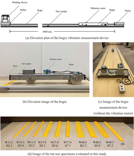
The bogie was placed on the floor and both its front and rear wheels were pulled over the specimen at a speed of 200 mm/s, 400 mm/s, or 600 mm/s by a rope wound using a constant-speed motor; the resulting LV was measured every 100 ms by a vibration meter (RION VM-55, RION Co., Ltd Citation2023) attached to the center of the bogie, as shown in . To investigate the significance of the differences among the vibrations induced by the various test specimens using the Kruskal – Wallis test (as presented in Section 4.2), each test was performed 30 times to obtain the average maximum vibration level (LVavg.max), defined as the average of the 30 maximum LV values for each specimen type (identified as the larger spike in ).
Figure 3. An example vibration level (LV) measurement (27.0 mm wide by 5.0 mm high curved specimen shown).
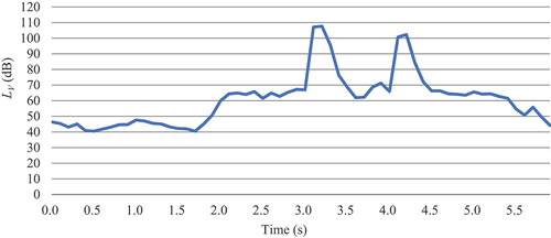
The types of vibrations that floor surfaces can induce in wheeled equipment include the constant vibration that occurs when wheels travel over gravel or tiled surfaces or the momentary vibration that occurs when wheels encounter a ledge. The maximum vibration level was used for the evaluation in this study because it best describes the temporary vibration that occurs when wheels pass over guide blocks. In the results, reference to “higher levels” or “greater values” indicate that the referenced vibration was more severe than that of the guide block under comparison, whereas “lower levels” or “lesser values” indicate the opposite.
4. Results
4.1. Vibration level
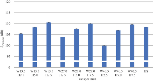
shows an example LV measurement. The two spikes in the curve represent the LV values when the front and rear wheels of the bogie passed over the test specimen. compares the LVavg.max values. Clearly, the larger the width and lower the height of the test specimen, the lower the LVavg.max. The lowest LVavg.max occurred for the 40.5 mm wide by 2.5 mm high specimen, and the highest LVavg.max occurred for the 13.5 mm wide by 7.5 mm high specimen. Comparing vibrations for the JIS specimen with those of the curved specimen of the same width (27.0 mm) and height (5.0 mm), the LVavg.max of the former was obviously higher.
Figure 4. Comparison of the average maximum vibration level (LVavg.max) values.
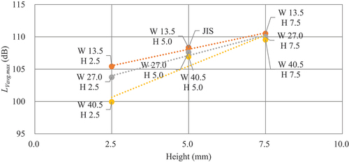
depicts the relationships between the width of the curved specimen and LVavg.max, indicating a negative linear relationship at any given height. For heights of 5.0 and 7.5 mm, the slopes of these relationships are comparable, but the slope is notably steeper for a height of 2.5 mm. shows the relationships between the height of the curved specimen and LVavg.max, indicating a positive linear relationship at any given width; the wider the specimen, the greater the decrease in LVavg.max as the height decreased. Together, demonstrate that LVavg.max was lower for six specimens with curved protrusion heights of 2.5 mm and 5.0 mm than for the JIS specimen.
Figure 5. Relationship between the width of the curved protrusion and average maximum vibration level (LVavg.max).
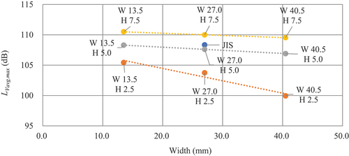
Figure 6. Relationship between the height of the curved protrusion and average maximum vibration level (LVavg.max).
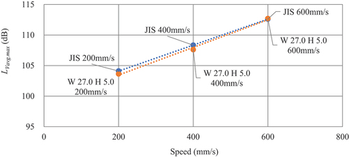
illustrates the relationship between speed and LVavg.max for the 27.0 mm wide by 5.0 mm high curved specimen, which match the width and height of the JIS specimen. For both specimens, the higher the speed, the higher the LVavg.max following a positive linear relationship. However, the slope of this relationship is steeper for the curved specimen than for the JIS specimen.
Figure 7. Relationship between the bogie passing speed and average maximum vibration level (LVavg.max).
4.2. Kruskal – Wallis test and multiple comparisons
A series of Kruskal – Wallis tests (ScienceDirect Topics Citation2023), which are used to determine the significant differences between three or more groups with no correspondence, was conducted to further analyze the differences between the LVavg.max values for the test specimens. In this study, multiple comparisons were made between the JIS and curved specimens using Dunnett’s test (Dunnett Citation1955) in a non-parametric manner (synonymous with Steel’s multiple comparison test). presents the resulting comparison of the LVavg.max values (using the JIS specimen tested at a passing speed of 400 mm/s as the Group 1 basis). In these multiple comparisons, the significant differences were below 1% for all curved shapes except for the 13.5 mm wide by 5.0 mm high specimen. The LVavg.max values of all 7.5 mm high specimens were greater than those of Group 1.
Table 2. Multiple comparisons of LVavg.max (using the JIS specimen at a passing speed of 400 mm/s as the Group 1 basis).
provides multiple comparisons of the LVavg.max values for the JIS specimen and the 27.0 mm wide by 5.0 mm high curved specimen (using the JIS specimen tested at a passing speed of 400 mm/s as the Group 1 basis). The significant differences were below 1% for all comparisons, and the LVavg.max values for the curved specimens tested at a passing speed of 600 mm/s were all greater than those for Group 1.
Table 3. Multiple comparisons of LVavg.max at different speeds for the JIS specimen and the 27.0 mm wide by 5.0 mm high curved specimen (using the JIS specimen at a passing speed of 400 mm/s as the Group 1 basis).
provides multiple comparisons of the LVavg.max values (using the 27.0 mm wide by 5.0 mm high curved specimen tested at a passing speed of 400 mm/s as the Group 1 basis). The significant differences were below the 1% level for all comparisons. The LVavg.max values for 13.5 mm wide by 5.0 mm high curved specimen, all three 7.5 mm high curved specimens, and the JIS specimen were all greater than those for Group 1. The LVavg.max values for all three 2.5 mm high curved specimens and the 40.5 mm wide by 5.0 mm high curved specimen were less than those for Group 1.
Table 4. Multiple comparisons of LVavg.max (using the 27.0 mm wide by 5.0 mm high curved specimen at a passing speed of 400 mm/s as the Group 1 basis).
provides multiple comparisons of the LVavg.max values for the JIS specimen and the 27.0 mm wide by 5.0 mm high curved specimen tested at different passing speeds (using the 27.0 mm wide by 5.0 mm high curved specimen tested at a passing speed of 400 mm/s as the Group 1 basis). The significant differences were below 1% for all comparisons, and the LVavg.max values for all curved specimens tested at a passing speed of 200 mm/s were less than those for Group 1.
Table 5. Multiple comparisons of LVavg.max at different speeds for the JIS specimen and the 27.0 mm wide by 5.0 mm high curved specimen (using the 27.0 mm wide by 5.0 mm high curved specimen at a passing speed of 400 mm/s as the basis).
5. Discussion
The results of this study can be applied to develop a projection shape for guide blocks that are able to effectively guide the visually impaired while inducing less vibration in passing wheeled equipment. The test specimens with curved protrusion heights of 5.0 mm or less, excluding the 13.5 mm wide by 5.0 mm high specimen, induced lower average maximum vibration levels than the JIS specimen. The average maximum vibration levels induced by the JIS and 13.5 mm wide by 5.0 mm high curved specimens can be considered comparable, as no significant differences were observed between them. Therefore, the shape that best suppresses the maximum vibration levels compared to the prismatic JIS protrusion is a convex curved protrusion 13.5 mm or more in width and 5.0 mm or less in height. When the height of the curved protrusion was 7.5 mm, the average maximum vibration level was consistently higher than that for the JIS protrusion even when the width was increased to 40.5 mm. Furthermore, the relationship between the passing speed and average maximum vibration level was generally linear, with higher speeds resulting in higher average maximum vibration levels.
Even when its width and height were 27.0 mm and 5.0 mm, respectively – the same as the prismatic JIS protrusion – the curved protrusion created a floor surface that induced less vibration in passing wheeled equipment. This geometry is likely to be acceptable for the guidance of visually impaired walkers as a previous study (Yanagihara, Kuwahata, and Hara Citation2013) found that the visually impaired can recognize a block with a linear protrusion 27.0 mm wide by 1.0 mm high provided for guidance. Thus, the curved projection shapes analyzed in this study can help to develop guide blocks that are easy for visually impaired persons to follow while providing a comfortable surface for the users of wheeled equipment. Future work should undertake experiments considering guide block material when evaluating the detection and discrimination abilities of visually impaired test subjects. In addition, the vibrations induced in different wheeled equipment types and configurations should be analyzed in detail. Finally, a survey to evaluate the sensation of passing over the proposed protrusion geometry is required to determine how much more comfortable people using wheeled equipment feel when passing over the proposed guide blocks compared to conventional guide blocks.
6. Conclusions
This study experimentally evaluated the vibration levels induced by the passage of wheels over different convex linear protrusion specimens representing guide blocks for the visually impaired. First, an experimental bogie device for measuring vibration levels was constructed and various test specimens were fabricated with a 3D printer. Vibration levels were measured as the bogie passed over these test specimens. A series of significant difference tests was subsequently conducted to analyze the differences in the average maximum vibration levels in detail, and the results indicated that curved shapes with widths greater than 13.5 mm and heights less than 5.0 mm exhibited reduced maximum vibration levels compared to the prismatic JIS guide block. However, the maximum vibration level induced by the curved shape was greater than that induced by the JIS block when the height of the former was greater than 5.0 mm, regardless of width. This quantitative evaluation indicated that making the linear projection of the guide block curved, widening its width, and lowering its height can significantly reduce the average maximum vibration level in wheeled equipment. Indeed, the results confirmed that a convex linear projection can have a smaller vibration impact on wheelchairs and other wheeled equipment while still effectively guiding the visually impaired. The findings of this study contribute to the development of guide blocks for the visually impaired that do not interfere with wheeled equipment and can serve as a guideline for future designs that ensure the comfortable use of walking spaces by both visually and non-visually impaired people.
Future studies should undertake experiments considering guide block materials when evaluating the detection and discrimination abilities of visually impaired test subjects. In addition, the vibrations induced in different types and configurations of wheeled equipment should be analyzed in detail.
Acknowledgements
This work was supported by JSPS KAKENHI Grant Number JP20K20126.
Disclosure statement
No potential conflict of interest was reported by the authors.
Additional information
Funding
Notes on contributors
Takashi Yamada
Takashi Yamada is a lecturer in the Department of Human Factors Engineering and Environmental Design, Kindai University, Japan. He received a Ph.D. from Keio University, Japan. His research covers human behavior modeling, simulation, and product design in buildings and urban spaces.
Atsuno Kuwabara
Atsuno Kuwabara received her B.E. from Kindai University. Her research interests include barrier free design and human behavior.
References
- Architectural Institute of Japan, YukaKoji WG. 2020a. “Floor Performance Evaluation Method and Performance Items with Recommended Values.” Accessed April 25, 2023. http://news-sv.aij.or.jp/zairyou/s10/YKWGindex1.html.
- Architectural Institute of Japan, YukaKoji WG. 2020b. “Vibration When Casters are Running.” Accessed April 25, 2023. http://news-sv.aij.or.jp/zairyou/s10/pdf/caster_shindou.pdf.
- Bentzen, B. L., A. C. Scott, R. W. Emerson, and J. M. Barlow. 2020. “Effect of Tactile Walking Surface Indicators on Travelers with Mobility Disabilities.” Transportation Research Record: Journal of the Transportation Research Board 2674 (7): 410–419. https://doi.org/10.1177/0361198120922995.
- Bourne, R. R. A., S. R. Flaxman, T. Braithwaite, M. V. Cicinelli, A. Das, J. B. Jonas, J. Keeffe, et al. 2017. “Magnitude, Temporal Trends, and Projections of the Global Prevalence of Blindness and Distance and Near Vision Impairment: A Systematic Review and Meta-Analysis.” The Lancet Global Health 5 (9): e888–e897. https://doi.org/10.1016/S2214-109X(17)30293-0.
- Cabinet Office, Government of Japan. “Annual Report on the Aging Society FY2021.” 2022. Accessed April 25, 2023. https://www8.cao.go.jp/kourei/whitepaper/w-2021/html/zenbun/s1_1_1.html.
- Courtney, A., and H. M. Chow. 2000. “A Study of Tile Design for Tactile Guide Pathways.” International Journal of Industrial Ergonomics 25 (6): 693–698. https://doi.org/10.1016/S0169-8141(99)00051-7.
- da Silva, F. M., L. A. Gachet Barbosa, R. C. Cecche Lintz, and A. E. P. G. A. Jacintho. 2015. “Investigation on the Properties of Concrete Tactile Paving Blocks Made with Recycled Tire Rubber.” Construction and Building Materials 91:71–79. https://doi.org/10.1016/j.conbuildmat.2015.05.027.
- Dunnett, C. W. 1955. “A Multiple Comparison Procedure for Comparing Several Treatments with a Control.” Journal of the American Statistical Association 50 (272): 1096–1121. https://doi.org/10.1080/01621459.1955.10501294.
- El-Taher, F. E., A. Taha, J. Courtney, and S. Mckeever. 2021. “A Systematic Review of Urban Navigation Systems for Visually Impaired People.” Sensors 21 (9): 3103. https://doi.org/10.3390/s21093103.
- Fernandes, H., P. Costa, V. Filipe, H. Paredes, and J. Barroso. 2017. “A Review of Assistive Spatial Orientation and Navigation Technologies for the Visually Impaired.” Universal Access in the Information Society 18 (1): 155–168. https://doi.org/10.1007/s10209-017-0570-8.
- Fujinami, K., N. Mizukami, H. Ohno, H. Suzuki, A. Shinomiya, O. Sueda, and M. Tauchi. 2005. “Tactile Ground Surface Indicator Widening and Its Effect on Users’ Detection Abilities.” Quarterly Report of RTRI 46 (1): 40–45. https://doi.org/10.2219/rtriqr.46.40.
- Fujisawa, S., and O. Sueda. 2012. “International Standard ISO 23599: 2012I Assistive Products for Blind and Vision Impaired Persons – Tactile Walking Surface Indicators.” Journal of Japanese Association for an Inclusive Society 14 (3): 21–27. https://doi.org/10.18975/jais.14.3_21.
- Giordano, B. L., Y. Visell, H.-Y. Yao, V. Hayward, J. R. Cooperstock, and S. McAdams. 2012. “Identification of Walked-Upon Materials in Auditory, Kinesthetic, Haptic, and Audio-Haptic Conditions.” The Journal of the Acoustical Society of America 131 (5): 4002–4012. https://doi.org/10.1121/1.3699205.
- Inagaki, T., S. Fujisawa, K. Takahashi, N. Ikeda, K. Takeuchi, H. Ogino, and S. Kobayakawa. 2017. “Experimental Observations on the Optimal Layout of Orientation Blocks for Safe Road Crossing by the Visually Impaired.” IATSS Research 41 (2): 82–88. https://doi.org/10.1016/j.iatssr.2017.06.005.
- Japan Federation of the Visually Impaired. 2014. “About Guidance Blocks for the Visually Impaired” Accessed June 25, 2023. http://nichimou.org/impaired-vision/barrier-free/induction-block/.
- Kobayashi, Y., Y. Mine, T. Takashima, and H. Fujimoto. 2006. “The Effect of Tactile Ground Surface Indicators to the Gait of Elderly with Normal Vision.” Transactions of the Japan Society of Mechanical Engineers Series C 72 (720): 2574–2579. https://doi.org/10.1299/kikaic.72.2574.
- Kobayashi, Y., R. Osaka, T. Hara, and H. Fujimoto. 2008. “How Accurately People Can Discriminate the Differences of Floor Materials with Various Elasticities.” IEEE Transactions on Neural Systems and Rehabilitation Engineering 16 (1): 99–105. https://doi.org/10.1109/tnsre.2007.910283.
- Kobayashi, Y., T. Takashima, M. Hayashi, and H. Fujimoto. 2003. “The Effect of Tactile Ground Surface Indicators to the Gait of Human with Normal Vision.” Transactions of the Japan Society of Mechanical Engineers Series C 69 (681): 1274–1280. https://doi.org/10.1299/kikaic.69.1274.
- Kobayashi, Y., T. Takashima, M. Hayashi, and H. Fujimoto. 2005. “Gait Analysis of People Walking on Tactile Ground Surface Indicators.” IEEE Transactions on Neural Systems and Rehabilitation Engineering 13 (1): 53–59. https://doi.org/10.1109/tnsre.2004.841880.
- Kuriakose, B., R. Shrestha, and F. E. Sandnes. 2020. “Tools and Technologies for Blind and Visually Impaired Navigation Support: A Review.” Iete Technical Review 39 (1): 3–18. https://doi.org/10.1080/02564602.2020.1819893.
- Lee, G.-W., K. Kim, C. J. Yoon, S. Yoon, and J.-H. Choi. 2016. “Development of Braille Block for Visually-Impaired Persons Using Unsaturated Polyester Resin.” Materials Today: Proceedings 3 (2): 99–103. https://doi.org/10.1016/j.matpr.2016.01.030.
- Low, W.-Y., M. Cao, J. De Vos, and R. Hickman. 2020. “The Journey Experience of Visually Impaired People on Public Transport in London.” Transport Policy 97:137–148. https://doi.org/10.1016/j.tranpol.2020.07.018.
- Lu, J., K. W. M. Siu, and P. Xu. 2008. “A Comparative Study of Tactile Paving Design Standards in Different Countries.” 2008 9th International Conference on Computer-Aided Industrial Design and Conceptual Design, November. Beijing, pp. 753–758. https://doi.org/10.1109/caidcd.2008.4730674.
- Ma, Y., X. Gu, W. Zhang, S. Hu, H. Liu, J. Zhao, and S. Chen. 2021. “Evaluating the Effectiveness of Crosswalk Tactile Paving on Street-Crossing Behavior: A Field Trial Study for People with Visual Impairment.” Accident Analysis & Prevention 163:106420. https://doi.org/10.1016/j.aap.2021.106420.
- Mitani, S., S. Fujisawa, O. Sueda, and T. Iwata. 2006. “Vibration Influence of Tactile Walking Surface Indicators on the Running of Manual Wheelchairs and Walking Frames.” IECON 2006 -32nd Annual Conference on IEEE Industrial Electronics, November. Paris, pp. 3910–3915. https://doi.org/10.1109/iecon.2006.347293.
- Mitani, S., S. Fujisawa, N. Yamada, M. Tauchi, T. Kato, and O. Sueda. 2007. “Detecting and Recognizing of Tactile Walking Surface Indicators by White Canes and by Foot-Sole.” Transactions of the Society of Instrument and Control Engineers 43 (3): 172–179. https://doi.org/10.9746/ve.sicetr1965.43.172.
- Mizuno, T., A. Nishidate, K. Tokuda, and K. Arai. 2008. “Installation Errors and Corrections in Tactile Ground Surface Indicators in Europe, America, Oceania and Asia.” IATSS Research 32 (2): 68–80. https://doi.org/10.1016/S0386-1112(14)60210-7.
- Ohno, H., N. Mizukami, and M. Tauchi. 2014. “International Standardization for Tactile Walking Surface Indicators(human Factors for Safety).” The Journal of Reliability Engineering Association of Japan 36 (2): 98–105. https://doi.org/10.11348/reajshinrai.36.2_98.
- Okamura, M. 2008. “Effect of Joint of Tile Pavement on Vibration of Wheel Chair and Comfort of Seated Person.” Doboku Gakkai Ronbunshuu E 64 (1): 237–246. https://doi.org/10.2208/jsceje.64.237.
- Onosokki. 2002. “Vibration Level Meter FAQ.” Accessed April 25, 2023. https://www.onosokki.co.jp/English/hp_e/c_support/faq/vr/vr6100_techterm.htm.
- Ormerod, M., R. Newton, H. MacLennan, M. Faruk, S. Thies, L. Kenney, D. Howard, and C. Nester. 2015. “Older People’s Experiences of Using Tactile Paving.” Proceedings of the Institution of Civil Engineers – Municipal Engineer 168 (1): 3–10. https://doi.org/10.1680/muen.14.00016.
- Øvstedal, L. R., I. M. Lid, and T. Lindland. 2005. “How to Evaluate the Effectiveness of a Tactile Surface Indicator System?” International Congress Series 1282:1051–1055. https://doi.org/10.1016/j.ics.2005.04.005.
- Øvstedal, L. R., T. Lindland, and I. M. Lid. 2005. “On Our Way Establishing National Guidelines on Tactile Surface Indicators.” International Congress Series 1282:1046–1050. https://doi.org/10.1016/j.ics.2005.04.004.
- Padzi, F. A., F. Ibrahim, and N. A. Karim. 2013. “Incongruent Installation of Tactile Ground Surface Indicator Toward Visual Impaired People’s Need: Masjid Jamek Station.” Procedia – Social & Behavioral Sciences 101:130–139. https://doi.org/10.1016/j.sbspro.2013.07.186.
- Park, J., and S. Chowdhury. 2018. “Investigating the Barriers in a Typical Journey by Public Transport Users with Disabilities.” Journal of Transport & Health 10:361–368. https://doi.org/10.1016/j.jth.2018.05.008.
- Parkin, J., and N. Smithies. 2012. “Accounting for the Needs of Blind and Visually Impaired People in Public Realm Design.” Journal of Urban Design 17 (1): 135–149. https://doi.org/10.1080/13574809.2012.646139.
- Pembuain, A., S. Priyanto, and L. B. Suparma. 2020. “The Evaluation of Tactile Ground Surface Indicator Condition and Effectiveness on the Sidewalk in Yogyakarta City, Indonesia.” IATSS Research 44 (1): 1–7. https://doi.org/10.1016/j.iatssr.2019.04.002.
- Pigeon, C., T. Li, F. Moreau, G. Pradel, and C. Marin-Lamellet. 2019. “Cognitive Load of Walking in People Who are Blind: Subjective and Objective Measures for Assessment.” Gait & Posture 67:43–49. https://doi.org/10.1016/j.gaitpost.2018.09.018.
- Pluijter, N., L. P. W. de Wit, S. M. Bruijn, and M. A. Plaisier. 2015. “Tactile Pavement for Guiding Walking Direction: An Assessment of Heading Direction and Gait Stability.” Gait & Posture 42 (4): 534–538. https://doi.org/10.1016/j.gaitpost.2015.08.009.
- Ranavolo, A., C. Conte, S. Iavicoli, M. Serrao, A. Silvetti, G. Sandrini, F. Pierelli, and F. Draicchio. 2011. “Walking Strategies of Visually Impaired People on Trapezoidal- and Sinusoidal-Section Tactile Groundsurface Indicators.” Ergonomics 54 (3): 246–256. https://doi.org/10.1080/00140139.2010.548533.
- Rey-Galindo, J. A., L. Rizo-Corona, E. L. González-Muñoz, and C. Aceves-González. 2020. “Environmental Information for People with Visual Impairment in Mexico – or What They Need and How They Use It.” Applied Ergonomics 85:103079. https://doi.org/10.1016/j.apergo.2020.103079.
- Riazi, A., F. Riazi, R. Yoosfi, and F. Bahmeei. 2016. “Outdoor Difficulties Experienced by a Group of Visually Impaired Iranian People.” Journal of Current Ophthalmology 28 (2): 85–90. https://doi.org/10.1016/j.joco.2016.04.002.
- RION Co., Ltd. 2023. “Vibration Level Meter VM-55.” Accessed April 25, 2023. https://svmeas.rion.co.jp/download/catalog/VM-55.
- ScienceDirect Topics. 2023. “Kruskal Wallis Test.” Accessed April 25, 2023. https://www.sciencedirect.com/topics/medicine-and-dentistry/kruskal-wallis-test.
- Ståhl, A., E. Newman, S. Dahlin-Ivanoff, M. Almén, and S. Iwarsson. 2010. “Detection of Warning Surfaces in Pedestrian Environments: The Importance for Blind People of Kerbs, Depth, and Structure of Tactile Surfaces.” Disability and Rehabilitation 32 (6): 469–482. https://doi.org/10.3109/09638280903171543.
- Suzuki, H., K. Fujinami, H. Ohno, N. Mizukami, O. Sueda, and M. Ide. 2001. “Stride Length and Speed of the Blind Walking Along Tactile Blocks in Their Daily Routines.” The Japanese Journal of Ergonomics 37 (4): 191–198. https://doi.org/10.5100/jje.37.191.
- Takamiya, S., and S. Hamada. 1998. “Information Used by Visually Impaired People While Walking.” Transportation Research Record: Journal of the Transportation Research Board 1636 (1): 104–109. https://doi.org/10.3141/1636-17.
- Takeda, M., Y. Watanabe, R. Takahashi, and M. Tauchi. 2006. “A Study for Directionality of Bar-Shaped, Tactile Walking Surface Indicator Examined by Vision Impaired Persons.” The Japanese Journal of Ergonomics 42 (3): 190–199. https://doi.org/10.5100/jje.42.190.
- Tanaka, N., and M. Iwata. 1997. “The Present Situation and Problems on the Tactile Warning Blocks from the View Point of Constructors and Users: Study on the Design of Guide Sign, Making Allowance for the Aged People in Welfare Town Planning.” Journal of Architecture and Planning (Transactions of AIJ) 62 (502): 179–186. https://doi.org/10.3130/aija.62.179_5.
- Thies, S. B., L. P. J. Kenney, D. Howard, C. Nester, M. Ormerod, R. Newton, R. Baker, M. Faruk, and H. MacLennan. 2011. “Biomechanics for Inclusive Urban Design: Effects of Tactile Paving on Older Adults’ Gait When Crossing the Street.” Journal of Biomechanics 44 (8): 1599–1604. https://doi.org/10.1016/j.jbiomech.2010.12.016.
- Tokuda, K. 2001. “Road Transport Barriers Encountered by People with Travel Difficulties in Japan.” IATSS Research 25 (1): 12–22. https://doi.org/10.1016/S0386-1112(14)60002-9.
- Vijaya Prakash, R., and S. Taduri. 2019. Safe Navigation for Elderly and Visually Impaired People Using Adhesive Tactile Walking Surface Indicators in Home Environment. Information and Communication Technology for Sustainable Development June Singapore: 771–778. https://doi.org/10.1007/978-981-13-7166-0_77.
- Wang, L., S. Nagarajaiah, W. Shi, and Y. Zhou. 2020a. “Study on Adaptive-Passive Eddy Current Pendulum Tuned Mass Damper for Wind-Induced Vibration Control.” The Structural Design of Tall & Special Buildings 29 (15): e1793. https://doi.org/10.1002/tal.1793.
- Wang, L., S. Nagarajaiah, W. Shi, and Y. Zhou. 2021. “Semi-Active Control of Walking-Induced Vibrations in Bridges Using Adaptive Tuned Mass Damper Considering Human-Structure-Interaction.” Engineering Structures 244:112743. https://doi.org/10.1016/j.engstruct.2021.112743.
- Wang, L., S. Nagarajaiah, W. Shi, and Y. Zhou. 2022. “Seismic Performance Improvement of Base-Isolated Structures Using a Semi-Active Tuned Mass Damper.” Engineering Structures 271:114963. https://doi.org/10.1016/j.engstruct.2022.114963.
- Wang, L., S. Nagarajaiah, Y. Zhou, and W. Shi. 2023. “Experimental Study on Adaptive-Passive Tuned Mass Damper with Variable Stiffness for Vertical Human-Induced Vibration Control.” Engineering Structures 280:115714. https://doi.org/10.1016/j.engstruct.2023.115714.
- Wang, L., W. Shi, X. Li, Q. Zhang, and Y. Zhou. 2019. “An Adaptive-Passive Retuning Device for a Pendulum Tuned Mass Damper Considering Mass Uncertainty and Optimum Frequency.” Structural Control and Health Monitoring 26 (7): e2377. https://doi.org/10.1002/stc.2377.
- Wang, L., W. Shi, Q. Zhang, and Y. Zhou. 2020c. “Study on Adaptive-Passive Multiple Tuned Mass Damper with Variable Mass for a Large-Span Floor Structure.” Engineering Structures 209:110010. https://doi.org/10.1016/j.engstruct.2019.110010.
- Wang, L., W. Shi, and Y. Zhou. 2022. “Adaptive-Passive Tuned Mass Damper for Structural Seismic Protection Including Soil–Structure Interaction.” Soil Dynamics and Earthquake Engineering 158:107298. https://doi.org/10.1016/j.soildyn.2022.107298.
- Wang, L., W. Shi, Y. Zhou, and Q. Zhang. 2020b. “Semi-Active Eddy Current Pendulum Tuned Mass Damper with Variable Frequency and Damping.” Smart Structures and Systems 25 (1): 65–80. https://doi.org/10.12989/sss.2020.25.1.065.
- World Health Organization. 2022. “Blindness and Vision Impairment.” Accessed April 25, 2023. https://www.who.int/news-room/fact-sheets/detail/blindness-and-visual-impairment.
- Yamada, T., and T. Yamazaki. 2019. “A Basic Study of Flat-Topped Tactile Walking Surface Indicators on Floors.” AIJ Journal of Technology and Design 25 (60): 609–614. https://doi.org/10.3130/aijt.25.609.
- Yanagihara, T., K. Kuwahata, and Y. Hara. 2013. “Tile Design for Tactile Guiding Patterns Easily Detectable Using a White Cane.” Journal of Architecture and Planning (Transactions of AIJ) 78 (683): 19–24. https://doi.org/10.3130/aija.78.19.