
 ?Mathematical formulae have been encoded as MathML and are displayed in this HTML version using MathJax in order to improve their display. Uncheck the box to turn MathJax off. This feature requires Javascript. Click on a formula to zoom.
ABSTRACT
In this study, the influence of different factors on pure bending members of recycled large-aggregate self-compacting concrete-filled steel tubes (RLA-SCCFSTs) was analyzed. Seven RLA-SCCFST members and one SCCFST member were designed to study their failure under a pure bending load and the influence of the steel tube wall thickness, RLA strength, and RLA particle size. The flexural bearing capacity was calculated using various codes. Based on the test results, ABAQUS and MIDAS FEA NX finite element analysis software were used to simulate and verify the test conditions. The results showed that under a pure bending load, the failure process of the RLA-SCCFSTs was much the same as that of an ordinary concrete-filled steel tube. Moreover, changes in the influencing factors resulted in different degrees of improvement in the flexural bearing capacity of the RLA-SCCFSTs. The factors most affecting the flexural members of the RLA-SCCFSTs – from large to small – included the steel tube wall thickness, RLA strength, and RLA particle size. The finite element simulation shows that the model based on the modified constitutive relation of core concrete was in good agreement with the experimental results. Among the various calculation methods for the bearing capacity, the results using the DBJ13-51-2003 specification were in good agreement with the test results. This study provides a reference for the reuse of waste concrete.
1. Introduction
Concrete-filled steel tubes are widely used in practical engineering as composite structures offering excellent performance. In fact, in many cities in China and abroad, concrete-filled steel tubes have been used as bending members in the construction of bridges, encouraging the acquisition of more theoretical data and the continued exploration of their mechanical properties.
Currently, owing to rapidly increasing urbanization, many buildings are being built, increasing the volume of construction waste (Shi et al. Citation2016). Consequently, to achieve sustainable development and protect the environment, waste aggregates are being recycled (Verian, Ashraf, and Cao Citation2018; Wang et al. Citation2020), a process which has also alleviated the shortage of natural resources. In recycled aggregate processing, there are inevitably a large number of small cracks within the material, which can greatly reduce the post-processing recycled aggregate performance (Xiao et al. Citation2022). Compared with natural aggregate concrete, recycled concrete can exhibit problems such as high porosity, high water absorption, and surface adhesion of mortar, making the mechanical properties and durability of the recycled concrete inferior to those of ordinary concrete, limiting the range of recycled concrete applications (Wang, Yu, and Li Citation2020; Medina et al. Citation2014; Nedeljković et al. Citation2021). To reduce the processing cost of recycled aggregates and avoid secondary pollution during the crushing process, (Li et al. Citation2016) conducted simple first-stage crushing and screening of waste aggregates. The mechanical properties of the recycled concrete prepared using 80-mm large-sized recycled aggregate were tested, and the feasibility of this method in practical engineering was demonstrated. Some scholars (Li and Xiao Citation2021; Li et al. Citation2019) used the discrete element method to establish the recycled large aggregate (RLA) random aggregate model to analyze the damage under stress, improving the strength and utilization rate of recycled concrete and compensating for defects in the recycled aggregate. Wang, Ma, and Yang (Citation2020); Wang et al. (Citation2021); Wu, Li, and Zhao (Citation2017) proposed that RLA and self-compacting concrete (SCC) be mixed and packed into a steel tube to form a recycled large-aggregate self-compacting concrete-filled steel tube (RLA-SCCFST) to improve the overall strength of the structure. Experimental research and modeling analyses of the compression conditions were conducted, the ultimate strength of the structure increasing with an increase in the wall thickness of the steel tube and the strength of the recycled aggregate. Moreover, the influence of the replacement rate of the recycled aggregate and load eccentricity on the mechanical properties of the components were emphasized. A formula for calculating the ultimate strength of an RLA-SCCFST was proposed. Through experimental research, (Li et al. Citation2018; Yu et al. Citation2019) concluded that the failure mode of RLA-SCC beams was the same as that of ordinary concrete beams. With an increase in the RLA replacement rate, the flexural strength of the RLA beams decreased.
From the above literature, it is evident that the current research has focused primarily on the influence of different recycled aggregate replacement rates, SCC strength, steel tube thickness, and eccentricity on the ultimate strength of RLA-SCCFST columns under compression. In addition to the above factors, the effect of the RLA particle size on the flexural mechanical properties of the RLA-SCCFST has been examined. Seven RLA-SCCFST members and one SCCFST member were used for a comparative study of the pure bending test. Through experiments, the influence of different parameters – such as the steel tube wall thickness, RLA strength, and RLA particle size – was summarized, and the entire process of stress and deformation of RLA-SCCFST pure bending members was analyzed. A finite element model of the RLA-SCCFST pure bending test member was developed using ABAQUS and MIDAS FEA NX finite element software and compared with the test results. The bearing capacities of RLA-SCCFST members in the pure bending state were calculated using different specifications. By comparing the formula values with the experimental values, the design rules, or specifications most suitable for RLA-SCCFST pure bending members were summarized.
2. Materials and methods
In this section, the mechanical properties of the materials in each part of the specimen are determined from a design and preparation perspective. Based on relevant research conducted by scholars, flexural RLA-SCCFST members are prepared, and the mechanical index and failure law of the RLA-SCCFST under a pure bending load is explored experimentally.
2.1. Material properties
Three standard tensile specimens were cut at different positions on three steel plates with different steel tube wall thicknesses. Tensile tests of nine standard tensile specimens were conducted on a universal machine under the test conditions and requirements specified in the ISO 6892–1:2016 standard (ISO Citation6892–1 2016), as shown in . The mechanical properties of the steel obtained from the tests are listed in .
Figure 1. Drawing of tensile test apparatus.
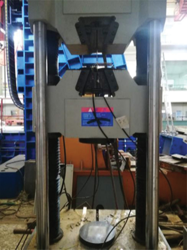
Table 1. Performance of steel.
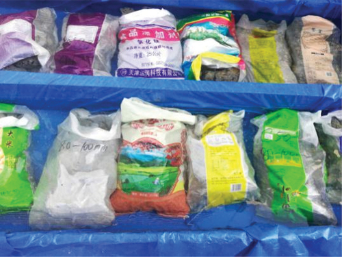
The RLA comprised abandoned beams obtained from a laboratory two years ago. The abandoned beams were broken into three sizes – that is, 60 ± 5, 90 ± 5, and 120 ± 5 mm – using mechanical and artificial crushing methods, after which they were bagged and recycled. The large aggregates are shown in . Inevitably, cracks occur within the RLA when it is crushed, significantly increasing its water absorption, thus affecting the SCC mix ratio. Therefore, the RLA in the bag was soaked in water for one day before pouring () so that it reached a saturated water-absorption state. It was then removed and surface-dried.
Figure 2. Photographs of regenerated macroaggregate with various particle sizes.
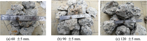
Figure 3. Regenerated aggregate in immersion.
Compared with recycled concrete, the particle size of the RLA may change, but the basic mechanical properties of the two remain essentially the same.
The two types of core concrete poured into the circular steel tubes were SCC and RLA-SCC. The SCC was designed based on C30 strength. The materials required for the SCC included ordinary Portland cement 42.5, medium coarse sand, natural coarse aggregate, fly ash, water, and polycarboxylate high performance water reducing agent (cementitious material content of 2–5%). The working performance of the SCC was evaluated using a slump expansion test, the RLA-SCC test blocks being experimentally measured under the same conditions. The measured cubic compressive strengths of the RLA-SCC specimens are presented in .
Table 2. The measured and calculated compressive strength of self-compacting concrete (SCC) cubes with reclaimed large aggregate.
Zhao, Wu, and Wang (Citation2016) summarized the effect of the change in the cube strength of the SCC and RLA on the combined strength of the RLA-SCC through many experimental studies on mixed components, their formula being as follows:
where denotes the RLA-SCC combination strength,
denotes the cubic compressive strength of the SCC, and
denotes the cubic compressive strength of the RLA.
The measured data shown in can be substituted into EquationEquation (1)(1)
(1) to obtain
and
, which can then be compared. Based on the Δ value, the error between
and
is small, suggesting that
is reliable.
2.2. Design and manufacture of specimen
Seven RLA-SCCFST members and one SCCFST member were fabricated. The length (L) of each member was 1400 mm and the outer diameter was 200 mm. The eight components formed a comparative relationship by changing the presence or absence of recycled aggregate, RLA particle size, RLA strength, and steel tube wall thickness. The specific groupings, sizes, and material parameters of the specimens are listed in .
Table 3. Specimen parameters.
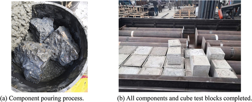
The steel was rolled into a hollow circular steel pipe based on the requirements and a butt joint was welded on the premise that the sections at both ends of the steel pipe remained flat. Using the geometric center of the steel pipe as the center, one end of the hollow circular steel pipe was welded to a cover plate of 240 × 240 × 20 mm, and the RLA and SCC were rotated into the steel pipe until the entire steel pipe was filled. After natural curing, the surface between the concrete and steel tube surfaces was smoothed, and another cover plate was welded to the top of the steel tube. All completed components were as shown in .
Figure 4. Fabrication of components.
2.3. Test method
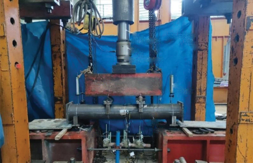
Through the loading device shown in , the three-point bending method was used to test the eight components. The loading equipment was a 1000-kN pressure-testing machine. An oil-pressure jack was loaded, the load applied by the pressure-testing machine being transmitted from the distribution beam to the third point of the specimen. The load applied by the pressure-testing machine was measured using a 1000-kN load sensor (an accurate load value being obtained by conversion after calibration). The strain deformation of the steel pipe surface was measured using a strain gauge and the deflection deformation of the specimen was measured using a displacement meter. The measured values of the displacement meters, sensors, and strain gauges were transmitted to a computer through an isolated measurement pod (IMP) acquisition system connected to the acquisition instrument.
Figure 5. Test loading device.
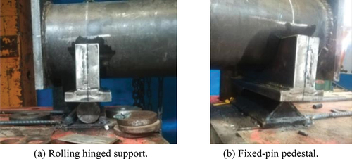
Owing to the smooth surface of the specimen, to have a fixed effect on the component, the support at both ends was specially built for the component during the test to achieve fixation of the component and to facilitate loading, as shown in .
Figure 6. The load bearing setup.
2.4. Measuring point setting and loading method
The load was measured using a 1000-kN sensor, and each specimen was arranged with a displacement meter and a strain gauge with a 150-mm range. A pair of transverse and longitudinal strain gauges were attached at the highest points on the upper, lower, left, and right surfaces of the steel tube in the middle of the specimen, with three displacement meters being placed in the pure bending section. A displacement meter was set up to detect bearing changes. The layout of the specimen measurement device is shown in .
Figure 7. The measuring device layout of the specimen.
Strain gauges 1–4 were longitudinally bonded and strain gauges 1“~ 4” were transversely bonded. The loading of the specimens was divided into three steps. The first stage was the elastic stage – that is, in a range of less than 60% of the ultimate load – and the graded loading was conducted based on a load increase of approximately 1/8 of the ultimate load. After the steel tube yielded – that is, more than 60% of the ultimate load – based on an increase of approximately 1/12 of the ultimate load, it was loaded at different levels according to the amplitude. During the third stage, as the component approached failure, the loading efficiency slowed, and the pressure was gradually increased.
3. Results and analysis
3.1. Experimental phenomena
During the initial loading stage, the load on the specimen continued to increase, and the deflection did not change much. During this period, the specimen exhibited a slight crackling sound, which may have been caused by uncompacted concrete. During the middle of loading, as the load continued to increase, the specimen generated some sound, and the deflection of the specimen increased considerably. Moreover, a warping phenomenon at both ends of the component became increasingly evident, and as the test progressed the deflection of the specimen increased sharply, there being an obvious large deformation. Until the test stopped – that is, the midspan displacement reached l/20—the load value did not decrease, indicating excellent deformation ability.
As shown in , the failure modes of the SCCFST and RLA-SCCFST specimens after the test failure were the same; the entire member is bent, the displacement of the middle part being the largest. Most members exhibit no compression deformation on the steel tube surface, with only a few specimens exhibiting expansion deformation near the three-point position; the influence of aggregation of components at the position at which the load was applied.
Figure 8. Failure modes of the specimens.
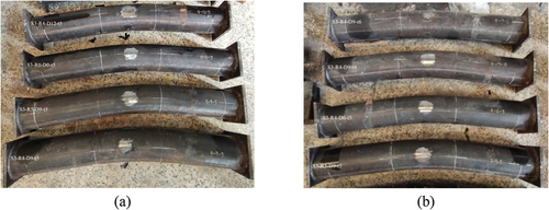
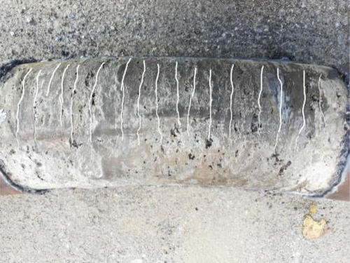
After the loading of the component was completed, the steel pipe of the bent part of the component was cut to study the cracking of the concrete within it. As shown in , different cracks are distributed in the concrete tension area of the component, the extension direction of the cracks gradually narrowing. Moreover, when the loading was completed, cracks developed in most of the high areas. In the area under pressure, this component exhibited no damage.
Figure 9. Failure conditions within the specimen.
3.2. Bending moment-midspan deflection curve
3.2.1. Effect of steel tube wall thickness on bending moment-midspan deflection curve
As shown in , the ultimate flexural capacity of the steel tube of wall thickness 5 mm is 13.15% higher than that of the steel tube of wall thickness 4 mm, and the ultimate flexural capacity of the steel tube of wall thickness 6 mm is 18.06% higher than that of the steel tube of wall thickness 5 mm. That is, the steel tube wall thickness (t) has a major effect on the RLA-SCCFST pure bending member curve.
Figure 10. The influence of the steel tube wall thickness on the bending moment-midspan deflection curve of the component.
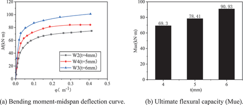
As shown in the figure, during the initial stages of loading, the slope of the curve gradually increases and tends toward the y-axis. It can be concluded that with an increase in the thickness of the steel tube, the ability of the component to resist bending is enhanced; thus, the overall bearing capacity of the component is enhanced. Moreover, as the load increases, the curve changes. With a change in the thickness of the steel tube, the difference in the bearing capacity between the members gradually increases, indicating that the thickness of the steel tube is positively linear with the ability of the member to resist bending. During the plastic stage, the rising speed of the curve gradually decreases, proving the ductility of the RLA-SCCFST to be strong.
3.2.2. Effect of RLA strength on bending moment-midspan deflection curve
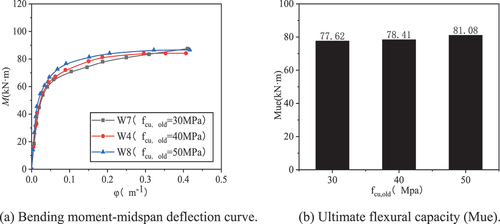
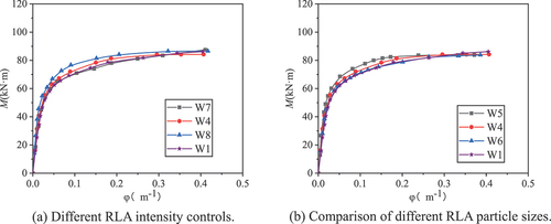
As shown in , the ultimate flexural bearing capacity at an RLA strength of 40 MPa is 1.02% higher than that at an RLA strength of 30 MPa, and the ultimate flexural bearing capacity at an RLA strength of 50 MPa is 3.41% higher than that at an RLA strength of 40 MPa. It is evident that the RLA strength is positively correlated with flexural bearing capacity. With an increase in the RLA strength, the difference in the flexural bearing capacity between the components increases.
Figure 11. The influence of the RLA strength on the bending moment-midspan deflection curve of the component.
3.2.3. Effect of RLA particle size on bending moment-midspan deflection curve
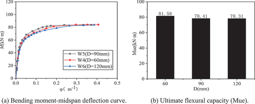
As shown in , the ultimate flexural capacity of the component made of 90-mm RLA is 4% lower than that of the 60-mm RLA component, and the ultimate flexural capacity of the component made of 120-mm RLA is 0.13% lower than that of the 90-mm RLA component. The RLA particle size and flexural capacity are linear, the ultimate flexural capacity of the component decreasing with increasing RLA particle size. When the recycled large-aggregate particle size is approximately 120 mm, the ultimate flexural capacity of the components remains unchanged.
Figure 12. Effect of the RLA particle size on the bending moment-midspan deflection curve.
3.3. Comparison between the RLA-SCCFST soil members and SCCFST members
By analyzing the bending moment-midspan deflection curve in , the change in the pure bending performance of SCC-filled steel tubular members with or without RLAs can be compared. It is evident from that the failure mode of the RLA-SCCFST pure bending members is the same as that of the ordinary SCCFST pure bending members – that is, the entire specimen is in a bending state, and the displacement in the middle of the members is the most significant.
Figure 13. Contrast of bending moment–midspan deflection curves.
The trends of the two types of components in the bending moment-span deflection curve are essentially the same. The ultimate flexural bearing capacity of recycled large-aggregate members with the same wall thickness is higher than that of ordinary steel tube RLA pure bending members. It is evident that components with large recycled aggregates have certain research significance and engineering applicability.
4. Discussion: comparison of bearing capacity results
Concrete-filled steel tube (CFST) structures are rapidly evolving, the research and achievements in CFST structures becoming increasingly refined. However, scholars from across the world have studied CFST structures from different perspectives, the difference lying in their definitions of the interaction between the steel tube and concrete. Consequently, the calculation methods for CFST structures have not been unified.
Accordingly, many countries have defined CFST calculation methods. In this study, the ultimate bearing capacity of RLA-SCCFST members under pure bending was calculated based on the following typical design specifications – that is, the AISC-LFRD (1999) specification (AISC Citation1999), European EC4 (1994) specification (Euro code 4 Citation1994), Japanese AIJ (1997) specification (AIJ Citation1997), Chinese specification GB50936 (2014) (Zhongming Citation2014), and Chinese Fujian DBJ13-51-2003 specification (DBJ13-51-Citation2003 Citation2003). A comparison of the experimental and calculated values is presented in .
Table 4. Comparison of measured and calculated values of flexural capacity of members.
shows a comparison between the calculation results and test values of the seven RLA-SCCFST members obtained based on the formulas of the five specifications. In the table, Mc represents the formula value and Mue represents the test value. As shown in , the calculated results agree well with the experimental values. The average calculated value of GB50936 (2014) in China is μ = 1.08, which is the closest to the experimental value; however, the standard deviation is μ = 0.025.
Compared with the AISC-LFRD (1999) specification, the AIJ (1997) specification and the DBJ13-51-2003 specification in Fujian Province, the standard deviation (σ) is too large, indicating that the calculated value of GB50936 (2014) in China is far from the average value (μ), the data is more dispersed, and the calculated value is higher than the experimental value.
After much consideration, it was suggested that the DBJ13-51-2003 code of Fujian Province be selected as the calculation formula for the ultimate flexural capacity of RLA-SCCFST pure bending members.
5. Model building
5.1. Material constitutive relationship
To strengthen finite element analysis research in the field of RLA-SCCFSTs, ABAQUS and MIDAS FEA NX finite element simulation software was used to establish a pure bending model of the RLA-SCCFST. The simulation results were compared with experimental data to verify the correctness of the material constitutive relationships and modeling methods.
1) Constitutive relationship of steel: The constitutive relationship model in the finite element model discussed in Ref (Dinis, Camotim, and Silvestre Citation2007) was selected as shown in . It meets the requirements of the steel von Mises yield criterion and usually includes the elastic (oa), elastoplastic (ab), plastic (bc), strengthening (cd), and secondary plastic flow (de) parts. The real stress-strain curve of steel is represented by the gray dotted line, and the equivalent stress-strain curve is represented by the black solid line.
Figure 14. Stress-strain curve of low carbon steel.
In this study, the equivalent stress-strain curve was used as the constitutive relationship model in the finite element model of RLA-SCCFST pure bending members. The constitutive relationship can be expressed as follows:
where denotes the elastic modulus of steel.
2) Constitutive relationship of core concrete: The plastic damage model of concrete was selected as the constitutive model for the core concrete in the finite element model. The model considered the failure of concrete to be a cracking failure under tension and a crushing failure under pressure. Therefore, the constitutive relationship of the core concrete includes two aspects – that is, the tensile and compressive constitutive relationships. The uniaxial compression constitutive relationship of the concrete core must consider its stress characteristics.
In this study, the Han (Linhai Citation2007) constitutive model was selected for the uniaxial compression constitutive relationship of the core concrete in the ABAQUS simulation. However, in the MIDAS FEA NX simulation, through correction of some parameters in the above constitutive model, the uniaxial compression constitutive relationship suitable for core concrete – namely, the stress-strain relationship – could be summarized, as follows:
In the finite element simulation, the constitutive relationship of the nonlinear part can be expressed by the real stress () and plastic strain (
) – that is,
and
are transformed from the nominal stress (
) and nominal strain (
) obtained by Eq. (3) above. The conversion formula can be expressed as follows:
where denotes the maximum stress of concrete,
denotes the strain corresponding to the maximum stress of concrete,
denotes the axial compressive strength of concrete cylinder,
denotes the axial compressive strength of concrete prism, and
and
denotes the cross-sectional area of steel tube and concrete, respectively.
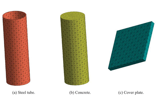
5.2. Entity establishment and grid division
The three parts – that is, the steel pipe, core concrete, and cover plate – were established using solid elements in the finite element software. The mesh size of each part was determined based on the size of the component and the trial simulation, the attributes of each component being meshed as shown in .
Figure 15. Grid division of each component.
5.3. Surface interaction
Based on the surface interaction, the contact type between the cover plate and other components was set to welding contact, the contact type between the steel pipe and concrete was set to general contact, and the friction coefficient between the two interfaces was set to 0.6.
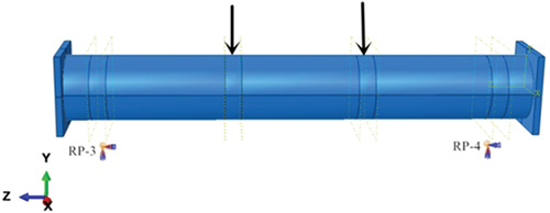
5.4. Boundary condition
As shown in , RP-3 limits the displacement in the x-, y-, and z-directions and the rotation of the component around y and z. RP-4 limits the displacement in the x- and y-directions and the rotation of the component around y and z. The loading system in the test was simulated by applying a load-through displacement – that is, a displacement of −52 mm being applied along the y-direction on the upper surface of the three-point steel tube.
Figure 16. The boundary conditions of the model.
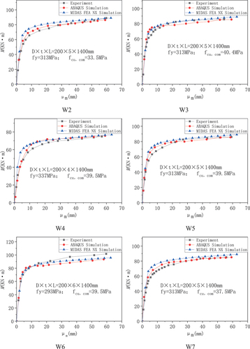
6. Comparison between simulation results and experimental data
To simplify the finite element software analysis, FEA NX and ABAQUS were used for the simulations. By comparing the modeling process with the simulation results, it was evident that FEA NX required less time to run and the model assembly was simpler, but the interaction analysis was weaker than that of ABAQUS.
shows a comparison of the -
curves between the test and the two finite element software results, where
denotes the midspan bending moment of the beam, and
denotes the midspan displacement. During the linear part of the curve, the angle coefficient of the simulated curve is slightly larger than that of the test curve, indicating that the initial bending stiffness of the former is slightly larger than that of the latter. During the elastic-plastic stage, the trend of the curve is essentially the same, and during the plastic strengthening stage, the simulation and test curves exhibit no downward trend. It is evident from the bending moment-deformation curve of the RLA-SCCFST pure bending members, that the simulation results are in good agreement with the experimental results.
Figure 17. Comparison of the moment-midspan displacement (M‒ curves.
7. Conclusions
In this study, the mechanical properties of an RLA-SCCFST under pure bending were studied experimentally and simulated through finite element analysis. The main conclusions drawn were as follows:
The flexural capacity of the RLA-SCCFST increased with the change of steel tube wall thickness, RLA strength, and RLA particle size. With increasing steel tube wall thickness and RLA strength, the flexural capacity of RLA-SCCFST increased. The effect of RLA particle size on the bending resistance of RLA-SCCFST was not obvious.
Among the five bending capacity calculation specifications, the bending capacity calculated using the DBJ13-51-2003 specification was the closest to the experimental results, with an average value of 0.81 and a standard deviation of 0.012—that is, it proved to be the best prediction model under comprehensive consideration.
The constitutive relationship of the core concrete was modified, and its accuracy was verified. When the test was reasonable, the constitutive model was used for the finite element analysis, and the simulation results were in good agreement with the experimental data.
This research provides important reference values for the secondary utilization of waste concrete, promoting environmental protection and sustainable development.
Although this paper has done a lot of research on the mechanical properties of RLA-SCCFST pure bending members, it is often accompanied by multiple loads in practical projects, and targeted research should be carried out on the fire resistance and seismic performance of members in the future.
Data statement
All data, models, and code generated or used during the study appear in the submitted article
Disclosure statement
No potential conflict of interest was reported by the author(s).
Additional information
Funding
Notes on contributors
Jianchao Wang
Jianchao Wang, Ph.D., An associate professor, Post-graduate student advisor, Research fields: Recycled concrete.
Huayu Li
Huayu Li, Post graduate, Research field: Recycled concrete filled steel.
References
- AIJ (Architectural Institute of Japan). 1997 October. Recommendations for Design and Construction of Concrete Filled Steel Tubular Structures [S]. Tokyo, Japan: Architectural Institute of Japan (AIJ).
- AISC. 1999. Load and Resistance Factor Design Specification for Structural Steel Buildings. Chicago: American Institute of Steel Construction Inc [S].
- DBJ13-51-2003. 2003. Technical Specification for Concrete-Filled Steel Tubular Structures. Fuzhou, China: The Construction Department of Fujian Province. in Chinese.
- Dinis, P. B., D. Camotim, and N. Silvestre. 2007. “FEM-Based Analysis of the Local-Plate/distortional Mode Interaction in Cold-Formed Steel Lipped Channel Columns.” Computers & Structures 85 (19–20): 1461–1474. https://doi.org/10.1016/j.compstruc.2007.02.013.
- Euro code 4. 1994. Design of Composite Steel and Concrete Structures, Part 1.1: General Rules and Rules for Buildings (Together with United Kingdom National Application Document) [S]. London, British: British Standards Institution. DD ENV1994-1- I:1994.
- ISO 6892-1. 2016. Metallic Materials Tensile Testing –Part 1: Method of Test at Room Temperature.
- Li, L., J. Chen, M. Zhou, G. Wu, Z. Huang, R. Li, Z. Yan, R. Fan, Z. Zhang, B. He, 2019. “Study on Mechanical Properties and Constitutive Relationship of Recycled Large Aggregate Concrete.” In IOP Conference Series: Earth and Environmental Science, Nha Trang, Vietnam, 042017. IOP Publishing.
- Li, J., T. Guo, S. Gao, L. Jiang, Z. Zhao, Y. Wang. 2018. “Study on Effects of Different Replacement Rate on Bending Behavior of Big Recycled Aggregate Self Compacting Concrete.” In IOP Conference Series: Materials Science and Engineering, Shanghai,China, 022032. IOP Publishing.
- Linhai, H. 2007. Concrete-Filled Steel Tubular Structure-Theory and Practice. Beijing: science press.
- Li, T., and J. Xiao. 2021. “Discrete Element Simulation Analysis of Biaxial Mechanical Properties of Concrete with Large-Size Recycled Aggregate.” Sustainability 13 (13): 7498. https://doi.org/10.3390/su13137498.
- Li, T., J. Xiao, C. Zhu, and Z. Zhong. 2016. “Experimental Study on Mechanical Behaviors of Concrete with Large-Size Recycled Coarse Aggregate.” Construction and Building Materials 120:321–328. https://doi.org/10.1016/j.conbuildmat.2016.05.110.
- Medina, C., W. Zhu, T. Howind, M. I. S. de Rojas, and M. Frías. 2014. “Influence of Mixed Recycled Aggregate on the Physical–Mechanical Properties of Recycled Concrete.” Journal of Cleaner Production 68:216–225. https://doi.org/10.1016/j.jclepro.2014.01.002.
- Nedeljković, M., J. Visser, B. Šavija, S. Valcke, and E. Schlangen. 2021. “Use of Fine Recycled Concrete Aggregates in Concrete: A Critical Review.” Journal of Building Engineering 38:102196. https://doi.org/10.1016/j.jobe.2021.102196.
- Shi, C., Y. Li, J. Zhang, W. Li, L. Chong, and Z. Xie. 2016. “Performance Enhancement of Recycled Concrete Aggregate–A Review.” Journal of Cleaner Production 112:466–472. https://doi.org/10.1016/j.jclepro.2015.08.057.
- Verian, K. P., W. Ashraf, and Y. Cao. 2018. “Properties of Recycled Concrete Aggregate and Their Influence in New Concrete Production, Resources.” Resources, Conservation and Recycling 133:30–49. https://doi.org/10.1016/j.resconrec.2018.02.005.
- Wang, J.-C., Z.-Z. Guan, Z.-M. Qiu, and W. Hou. 2021. “Experimental Study on Short Steel Tube Columns Filled with Recycled Large Aggregate-Self Compacting Concrete Subjected to Compression.” Science of Advanced Materials 13 (5): 991–1002. https://doi.org/10.1166/sam.2021.3998.
- Wang, J., G. Ma, W. Yang. 2020. “Finite Element Simulation of Recycled Large Aggregate Self-Compacting Concrete Short Columns with Steel Tubes.” In IOP Conference Series: Earth and Environmental Science, Guiyang, China, 012178. IOP Publishing.
- Wang, R., N. Yu, and Y. Li. 2020. “Methods for Improving the Microstructure of Recycled Concrete Aggregate: A Review.” Construction and Building Materials 242:118164. https://doi.org/10.1016/j.conbuildmat.2020.118164.
- Wang, J., J. Zhang, D. Cao, H. Dang, and B. Ding. 2020. “Comparison of Recycled Aggregate Treatment Methods on the Performance for Recycled Concrete.” Construction and Building Materials 234:117366. https://doi.org/10.1016/j.conbuildmat.2019.117366.
- Wu, B., W.-F. Li, and X.-Y. Zhao. 2017. “Behavior of Slender Square Steel Tubular Columns Filled with Fresh Concrete and Demolished Concrete Lumps.” Procedia Engineering 210:196–202. https://doi.org/10.1016/j.proeng.2017.11.066.
- Xiao, J., C. S. Poon, Y. Wang, Zhao, Y., Ding, T., Geng, Y., and Li, L. 2022. “Fundamental Behaviour of Recycled Aggregate Concrete – Overview I: Strength and Deformation.” Magazine of Concrete Research 74 (19): 999–1010. https://doi.org/10.1680/jmacr.21.00253
- Yu, F., L. Yin, Y. Fang, and J. Jiang. 2019. “Mechanical Behavior of Recycled Coarse Aggregates Self‐Compacting Concrete‐Filled Steel Tubular Columns Under Eccentric Compression.” Structural Concrete 20 (6): 2000–2014. https://doi.org/10.1002/suco.201900267.
- Zhao, X.-Y., B. Wu, and L. Wang. 2016. “Structural Response of Thin-Walled Circular Steel Tubular Columns Filled with Demolished Concrete Lumps and Fresh Concrete.” Construction and Building Materials 129:216–242. https://doi.org/10.1016/j.conbuildmat.2016.10.099.
- Zhongming, L. W. 2014. Technical Specification for Concrete-Filled Steel Tube Structures: GB50936–2014. Beijing: China Construction Industry Press.