
 ?Mathematical formulae have been encoded as MathML and are displayed in this HTML version using MathJax in order to improve their display. Uncheck the box to turn MathJax off. This feature requires Javascript. Click on a formula to zoom.
ABSTRACT
Deployable membrane structures have played a vital role in creating flexible and adaptable urban and architectural spaces. However, the geometries of deployable membrane structures are often confined to symmetrical and regular shapes, due to the complex interdependencies between structure, material, motion, and geometry. To overcome this challenge, this research proposes a new category of deployable membrane structures that enables a broad range of deployment geometries, including free forms. The proposed system facilitates the transformation of arbitrary free-form surfaces into structural models, simplifies kinematic analysis for free-form deployment, and reduces structural calculations for free-form deployable structures. This study systematically investigated the proposed deployable membrane system in terms of geometric characteristics, deployment mechanisms, and digital manufacturing methods, including investigations of the generation method and geometric categories, summarizations of the folding mode and foldability conditions, and explorations of the CNC manufacturing logic and the G-code generation method. Finally, a full-scale physical prototype is studied to validate the proposed system and related methods.
1. Introduction
Deployable structures are advanced engineering systems capable of transforming from compact configurations into stable structures that cover specific areas (Pellegrino Citation2001). These structures have a range of applications in various fields, including architecture, aerospace, and other engineering disciplines. Numerous design prototypes have been proposed in the latter half of the 20th century, including the foldable reticular structure and the deployable theatre designed by Spanish architect Emilio Perez Pinero (Perez Citation1965), the large deployable inverted umbrellas designed by German architect Frei Otto (Otto Citation1973), and the scissor structures designed by American engineer Hoberman (Hoberman Citation2006). Researchers have systematically classified and analyzed deployable structures in terms of structural forms (e.g., lattice structures, continuous structures, etc.), component types (e.g., rods, membranes, plates, etc.), and deployment mechanisms (e.g., rigid connections, flexible deformations) (De Temmerman Citation2007; Del Grosso and Basso Citation2013; Escrig Citation1996; Gantes Citation2001; Hanaor and Levy Citation2001; Pellegrino Citation2001).
Deployable membrane structures constitute a significant category of deployable structures and play a critical role in the development of adaptable urban and architectural spaces. These structures consist of membrane materials and support systems, where the use of membrane materials allows for a lighter self-weight and a larger deployable area (Zhang et al. Citation2021). Deployable membrane structures have a wide range of applications in public urban and architectural spaces, and numerous deployable membrane structures have been successfully constructed since 2000. Examples include the retractable membrane roofs of the Al Janoub and Al Bayt stadiums for the FIFA 2022 World Cup, as well as the retractable membrane shading of the Medina Haram Piazza in Saudi Arabia and the Al Bahar Towers.
Despite the widespread use of deployable membrane structures in architecture, their geometries are often restricted to symmetrical and regular shapes such as circles, squares, spheres, cylinders, and others. This limitation is due to the complex interdependence between geometry, structure, and movement. And this limitation poses a challenge when it comes to designing complex architectural or urban spaces.
The purpose of this research is to overcome the geometric limitations of deployable membrane structures by developing a flexible and robust deployable membrane system. The proposed system expands deployment geometries to encompass free forms while streamlining the design process for free-form deployable membrane structures. Keys to the proposed system include the adoption of unit organization, self-supporting components, and straightforward interactions between tension and compression members. This results in effortless transformation from free-form surfaces to structural models, simplification of kinematic analysis for free-form deployment, and reduction of structural calculations from free-form surface structures to individual self-supporting components.
This research first investigates the geometric characteristics, deployment mechanisms, and digital fabrication methods of the deployable membrane system. Subsequently, a full-scale prototype was studied to verify the proposed system and associated methods.
2. Literature review
2.1. Research on deployable membrane structures
The emergence of deployable membrane structures can be traced back to ancient times, as evidenced by the scissor chair in the Babylonian terracotta tablet and the textile awning of the Roman Colosseum. In modern times, large-scale deployable membrane structures have been widely applied and studied in the fields of aerospace engineering and architectural engineering. In aerospace engineering, researchers have explored the use of deployable membrane structures for antenna structures and solar wings, and have conducted extensive studies on form-finding methods, shape control methods, static/dynamic analysis, folding schemes, and actuation modes (Chandra et al. Citation2021; Pellegrino Citation2001). In architectural engineering, pioneers such as Frei Otto and Buckminster Fuller began researching deployable membrane structures in the 1960s and 1970s. They explored potential forms and design methods for retractable membrane roofs (Blümel Citation1972), retractable pneumatic structures (Blümel Citation1975), tensegrity structures (Buckminster Citation1962), and studied their construction types, structure types, and motion types. Nowadays, the research scope has expanded to novel types of deployable membrane structures, such as membrane tensegrity structures (Gupta et al. Citation2020; Riether, Wit, and Putt Citation2015; Tracy et al. Citation2019; Yang and Sultan Citation2016), inflatable tensegrity structures (De Laet et al. Citation2009; Dessi-Olive et al. Citation2019), inflatable origami structures (Melancon et al. Citation2021), and so on. Meanwhile, the architectural application of deployable membrane structures has also expanded from retractable roofs (Lienhard and Kugel Citation2015; Mollaert Citation1996) to adaptive facades (Attia Citation2016; Eisenbarth et al. Citation2021), and interior partitions (Wyller et al. Citation2020).
However, there are still challenges that need to be addressed in the design and engineering of free-form deployable membrane structures, including difficulties in structural calculations, deployment geometry control, folding schemes, and fabrication methods. This research proposes a deployable membrane system that presents a practical and promising solution to the aforementioned challenges.
2.2. Research on free-form deployable structures
Several methods have been proposed to generate free-form deployable structures, including deployable scissor structures, elastic structures, origami structures, tensegrity structures, and pneumatic structures. Roovers and Temmerman et al. developed methods based on principle curvature computation and circle-packing algorithms to transform arbitrary surfaces into deployable scissor structures (Roovers and Temmerman Citation2015; Roovers, Mira, and De Temmerman Citation2013). Zheng et al. (Zheng, Sun, and Chen Citation2016) presented a general way to construct scissor linkages from arbitrary 3D shapes. Chen et al. (Chen et al. Citation2021) suggested a class of deployable surface structures composed of bistable elastic cells that can achieve effective deployment toward desired double-curved target shapes. Ren et al. (Ren et al. Citation2022) introduced a computational design method for a new class of deployable structures consisting of elastic beams, rigid plates, and hinges that can be deployed from a compact volume into bending-active free-form surfaces. The method was generalized to 3D surfaces with arbitrary, even non-convex boundaries by Pillwein and colleagues (Pillwein and Musialski Citation2021). Dudte et al. presented a method to generate origami patterns for folded deployable structures to obtain 3D surfaces. Rieffel et al. introduced a generative and grammatical graph-based approach for the design and optimization of large, complex, and irregular tensegrity structures (Rieffel, Valero-Cuevas, and Lipson Citation2009). Tachi proposed a novel interactive method to generate and edit free-form tensegrity structures from an arbitrary polygon mesh using topology generation, form finding, and projection (Tachi Citation2012). Skouras proposed an interactive, optimization-in-the-loop computational tool for constructing inflatable structures from arbitrary target shapes (Skouras et al. Citation2014). Panetta et al. proposed a computational inverse design method that can generate inflatable structures from complex surface geometries (Panetta et al. Citation2021).
Previous research on generating free-form deployable structures has been a profound source of inspiration and provided useful references for computational generation methods in this research. In contrast to the deployable structures based on scissors, origami, and bending mechanisms, the proposed deployable membrane system uses a distinctive folding mechanism that is influenced by customized fabrics. Unlike tensegrity and inflatable deployable structures, the proposed system utilizes a different connectivity pattern of tension and compression components, which leads to more straightforward interactions between the components. Therefore, the generation methods, dynamic analysis, and structural calculations of the proposed system are different from and simpler than those of the aforementioned deployable membrane structures, making related applications more controllable and practical.
2.3. Research on CNC knitting
Research on CNC knitting in architecture encompasses various areas, such as textile hybrids, concrete formwork, smart interfaces, and composite structures. Martin Tamke, Mette Ramsgaard Thomsen, and their research group investigated design-to-fabrication systems and computational approaches for bending-active knit hybrids (Tamke et al. Citation2020; Thomsen et al. Citation2019). They also evaluated the potential of computational knitting for novel textile structures. Sean Ahlquist et al. studied computational design frameworks for bending-active and inflatable textile hybrids that integrate knit material information and performance with design computation (Ahlquist and Menges Citation2013; Ahlquist, Mcgee, and Sharmin Citation2017). Tracy Sachin and Sean Gupta et al. devised novel knitted membrane tensegrity shells and related computational workflows (Gupta et al. Citation2020; Tracy et al. Citation2019). These structures feature large structural openings and employ graded CNC-knitted textiles to accommodate stress concentrations informed by structural analysis data. Mariana Popescu et al. demonstrated the structural design, digital fabrication, and construction approaches for ultralight knitted formwork (Popescu et al. Citation2021), and successfully applied them to the creation of complex concrete structures.
Previous research has also investigated the generation of knit patterns from 3D design models. Narayanan et al. proposed a fully automated approach to convert arbitrary 3D meshes directly into knitting instructions for computerized v-bed knitting machines (Narayanan et al. Citation2018). Wu et al. developed a fully automated pipeline capable of converting arbitrary 3D meshes into knittable stitch meshes (Wu, Swan, and Yuksel Citation2019). Tamke Martin et al. presented a computational workflow that employs planarization and length relaxation to transform 3D meshes into 2D knitting patterns (Tamke et al. Citation2020). Mariana Popescu et al. proposed an approach that transforms non-developable surfaces into knitting patterns (Popescu et al. Citation2017). Yige Liu et al. explored a computational approach for generating one-stroke knitting paths and 2D knitting patterns from 3D meshes for composite structures (Yige, Li, and Philip Citation2019).
The above research provides useful tools and methodological references for designing, form-finding, and fabricating the deployable membrane system. There are primarily two differences between the earlier research and this research. First, in this research, CNC-knitted fabrics are used as customized hinges, which feature shape control capability for free-form deployment. Second, this research proposes a distinct knitting pattern generation approach, which allows piecewise knitting path adjustment and increases the utilization of the available knitting width of the machines to enhance production efficiency.
2.4. Research gap
In conclusion, the previous research lacks simple and effective design methods for practical applications of free-form deployable membrane structures as well as an in-depth discussion of the utilization of CNC machining technology to enhance the design of deployable membrane structures.
To fill this gap, this research proposes a novel deployable membrane system based on CNC knitting and CNC bending to streamline the design process of free-form deployable membrane structures. Additionally, this study investigates the shape control capabilities and structural characteristics of CNC-manufactured components for such structures. This research also improves digital fabrication techniques based on the characteristics of deployable membrane structures and offers a unique approach to generating fabrication data.
3. Geometric characteristics
This section examines the morphological principles and capabilities of the deployable membrane system. To achieve this, the section will explore the system’s geometric characteristics, investigating crucial aspects like basic composition, generation methods, and geometry categories.
3.1. Basic composition
The deployable membrane system in this research adopts a unit composition and uses CNC-knitted fabrics and CNC-bent frames as its main components, as shown in . Each unit consists of multiple frames and a single knitted fabric connected to the frames. The units are independent and self-supporting. They are connected by attaching adjacent frames to form the overall structure.
Figure 1. Main components (a), a unit(b), a combination of units(c) in the deployable membrane system.
The CNC-knitted fabrics function as the deployment hinge of the system and form the surface enclosure. These fabrics are automatically produced by CNC flat knitting machines and can be precisely coded stitch by stitch to create custom shapes and details. The fabric and frame are joined by inserting the frame bar into the sleeve at the fabric edge and securing the adjacent fabric edges by bolting the adjacent bars together, as shown in . Joint details such as bolt holes in the sleeve and frame are aligned.
Figure 2. Joint between fabric and frame(a), frames with an I-shaped section(b), frames with a triangular section(c), frames with a rectangular section(d).
The CNC-bent frames function as the primary structural support and the connection between the units. The frames consist of multiple bent bars and straight crossbars. The axis of the frames consists of planar arcs. The bent frames are manufactured on CNC bending machines and can be customized to approximate any curved shape. The cross-section of the frame is customized to meet the structural design requirements as shown in . Typical cross-section includes I-shape, triangle shape, rectangle shape, and others.
3.2. Generation method
The unit composition and simple component geometries facilitate the generation of the proposed deployable membrane structures from arbitrary free-form surfaces. The generation process consists of three steps, including surface unitization, unit rationalization, and form-finding, as shown in .
Figure 3. The generation process.
In surface unitization, the target surface is intersected by multiple planes and segmented into units. The segmented surfaces become the fabric surfaces and the intersection curves become the frame axes. The division pattern and density are very flexible, but the actual construction constraints must be taken into account, such as the frames cannot be in the air or intersect each other, the equilibrium form of the fabrics is close to the target surface, and so on.
In unit rationalization, the fabric surfaces and frame axes are reconstructed according to manufacturing requirements. As depicted in , the fabric surfaces are reconstructed into developable surfaces that can be flattened without distortion for knitting production on flat knitting machines. The frame axes are reconstructed into tangentially connected circular arcs that follow the manufacturing logic of the CNC circular bending machines. The fabric surface is reconstructed by sweeping straight lines along a directrix or computing local convex hulls of surface boundaries (Rose et al. Citation2007). The frame axis is reconstructed by splitting input curves and fitting circular arcs between adjacent splitting points according to tangent vectors. The rationalization of fabric surfaces and frame axes considers the manufacturing constraints of the knitting and bending machines. For instance, the fabric width must not surpass the maximum knitting width, and the radius of the arc must not exceed the minimum bending value.
Figure 4. Rationalization of fabric surfaces and frame axes.
In form-finding, the reconstructed fabric surfaces are transformed into equilibrated doubly curved surfaces by applying the force density method (Schek Citation1974). The form-finding model assumes the fabrics are fixed to static frames. The input loads are the dead weights of the fabrics, and the input force density q is determined by calculating the best-fit equilibrium geometry for the target geometry. The calculation of the best-fit equilibrium geometry is achieved by using the least squares method to calculate the minimum sum of residual squares of the vertex coordinates between the target geometry and the equilibrium geometry.
3.3. Geometric categories
At the unit level, the geometries of the deployable membrane system can be classified into four categories according to their base geometries of developable surfaces, as depicted in . The first category comprises unit geometries based on cylindrical surfaces. Cylindrical surfaces have parallel rulings and are generated by moving a line segment along a directrix. The second category consists of unit geometries based on conical surfaces, where all rulings are fixed at a vertex and sweep along a fixed curve. The third category includes unit geometries based on tangent developable surfaces, where all the rulings are tangent to the directrix. The fourth category contains unit geometries based on composite developable surfaces, which are the combinations of the above developable surfaces.
Figure 5. Geometry categories at the unit level.
At the combination level, the geometries of the deployable membrane system exhibit an infinite range of variations depending on their combination patterns, unit numbers, and unit geometries. These geometries can be divided into four categories as shown in , each with unique architectural spatial properties as summarized by Ching (Ching Citation2023). The first category includes centralized geometries, where units are arranged around a central, dominant parent space. The second category features linear geometries, where units are arranged sequentially in a row. The third category showcases radial geometries, where units are arranged in a linear, compositional form that extends outward in a radial fashion. The fourth category contains reticular geometries where units are connected in a network structure.
Figure 6. Geometry categories at the combination level.
These categories of geometries allow a wide range of design possibilities for the deployable membrane system, ensuring its versatility and adaptability to different architectural contexts and spatial requirements.
4. Deployment mechanisms
To study the deployment mechanisms of the deployable membrane system, this section investigates the folding mode, the necessary conditions for foldability, and the geometric control capability of CNC-knitted fabrics.
4.1. Folding mode and necessary conditions for foldability
The proposed deployable membrane system has simplified free-form deployment by enabling the independent deployment of the units and self-supporting components. The system can fold reversibly from a spatial enclosure to a compact parallel arrangement allowing for efficient storage and transport.
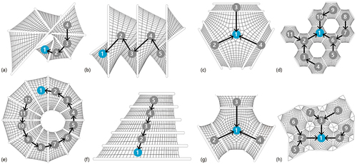
The folding diagrams of the deployable membrane system can be described using rooted tree graphs, where each vertex represents a unit and each edge represents the connection between two adjacent units, as depicted in . There is one designated unit, called the root unit, to which all other units are connected. Units with vertex degree 1 are called leaf units, while the intermediate units are called internal units. The folding sequence typically begins with leaf units, progresses through internal units, and culminates at a root unit.
Figure 7. The folding diagram.
To ensure foldability, two necessary conditions must be met. One of the necessary conditions is that the CNC-bent frames must not collide with each other during deployment. To avoid collisions, the shortest distance between any two frame curves should be calculated. Assume the minimum distance between the i-th frame curve and the j-th frame curve is ,
, and the total number of frames is
. To achieve foldability, the minimum distance
should always be
, where d is a positive value determined by the profile size of the frame.
The other necessary condition is that the CNC-knitted fabrics must not be overstretched during deployment. The stretch can be evaluated by calculating the length variations of the ruling curves of the fabric surfaces. Assume the length of the k-th ruling curve on the CNC-knitted fabrics at the fully unfolded state is ,
, the total number of ruling curves is
,
and
are the end points of the k-th ruling curve, and
is the linear distance between point
and
during deployment. To avoid stretching,
should always follow:
throughout the deployment process.
4.2. Geometric control
CNC-knitted fabrics play a critical role in controlling the geometry of the deployable membrane system during deployment. While the movement and position of the frames are independent, the CNC-knitted fabrics impose spatial constraints on the frames through their custom contours , as depicted in .
Figure 8. Geometry control through custom fabric contour.
The fabrics’ geometry control capability is realized through local tension increases. When the frames deviate from their target positions, local tension increments are created to restrict the movement of the frames and prevent them from moving too far from their designated positions. These local tension increments ensure that the frames follow prescribed folding paths and maintain their desired spatial relationships.
5. Manufacturing methods
CNC manufacturing technologies provide the deployable membrane system with enhanced geometric freedom and improved constructability. This section summarizes the CNC manufacturing logic of the deployable membrane system and proposes a new knitting pattern generation method to improve the manufacturing efficiency of the deployable membrane system.
5.1. Logic of CNC bending and knitting
The CNC-bent frames of the deployable membrane system are manufactured on automatic three-roll bending machines. Three-roll bending machine is a general forming equipment for rolling metal bars into curved shapes. According to the principle of the three-point forming circle, the relative position change and rotational movement of working rollers make the metal bars produce continuous plastic deformation, so as to obtain the predetermined shape. In this research, we adjust the vertical distance between the top roller and the side rollers to achieve the desired bending radius, as illustrated in . The mathematical relationship between the bending radius r and the roller settings can be expressed as follows:
Figure 9. Diagram of the three-roll bending machine.
where denotes the bending radius,
denotes the radius of the rollers,
denotes the section diameter of the bent bar,
denotes the vertical distance between the center of the top roller and the center of the side rollers, and
denotes half the center distance between the side rollers.
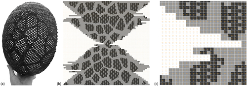
The CNC-knitted fabrics of the deployable membrane system are fabricated using an automated flat knitting machine. The flat knitting machine uses a knitting carriage to slide along the length of the horizontal needle bed row by row to create a fabric. It uses a 2D pixel-based knitting pattern drawing to instruct the knitting process and control the movement of the carriage and needles, as illustrated in . In this drawing, each pixel represents a knit, each pixel row corresponds to a knitting course, and each pixel column represents a knitting wale. By manipulating different combinations of pixel rows and columns, different fabric geometries can be created. Pixels of different colors or modules mark different details of the fabric, including opening holes, shaping edges, color variations, and so on, which can be predefined by the user. The 2D pixel-based knitting pattern can be recognized by knitting software and automatically translated into G-code for knitting machines.
Figure 10. The knitted object(a), the pixel-based knitting pattern(b), enlarged detail of the knitting pattern(c).
5.2. Knitting pattern generation
The major challenge in the digital fabrication of the deployable membrane system is the generation of knitting patterns.
Unlike other research, this research proposes a method that not only automatically generates knitting patterns from the given fabric contours, but also allows the knitting direction to be adjusted, as shown in . With this method, the knitting path closely matches the geometry of the fabric and maximizes the use of the machine’s available knitting width.
Figure 11. Diagram of the knitting pattern generation method.
In this method, the developable surface of a CNC-knitted fabric is flattened on the XY plane as the surface S”. f(t) is a contour curve of the surface S”, and the knitting path is a polyline Sgn(t), whose breakpoints are the sample points on the curve f(t). Users adjust the number and position of the sample points to obtain the ideal knitting path.
After the ideal knitting path is generated, the polyline Sgn(t) is offset by knit width and trimmed by the contour of the surface S” to create the knit columns. Next, the offset polylines are divided into segments at breakpoints and transformed into an orthogonal point grid of knits. The transformation operations include rotation and translation, and are performed segment by segment. The segments are arranged along the y-axis in their original order. Finally, the grid of knit is translated into 2D pixel drawings in bmp format through a series of image processing operations, including non-uniform scaling, length rounding, and equidistant sampling.
The final knitting pattern in the form of a segmented shape is knitted as a single piece of fabric. The segments are automatically joined during the knitting process using a technique called short-row knitting. Short-row knitting partially knits each row’s stitches, leaving unknitted stitches in their original positions within the needle hooks until they are requested to join the knitting process again. Short-row knitting is a common technique used to create custom shapes for knitted fabrics. Wedge-shaped openings are featured in short-row knitting patterns, as shown in .
Figure 12. A typical knitting pattern(a), a typical knitting diagram(b), a typical knit structure(c) of short row knitting.
6. Prototype design and fabrication
The proposed deployable membrane system and its associated methods were validated by conducting a thorough investigation of a full-scale prototype. This research examined the structural characteristics, folding behaviors, and manufacturing capabilities of the prototype.
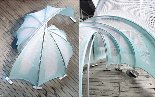
The prototype was designed and built during the DigitalFUTURES international workshop. It has a size of 8 square meters as a pavilion, with a total surface area of 21 square meters. It is on display for one month at Tongji University, as shown in . The prototype has a central spiral-shaped surface when fully unfolded, and becomes a compact volume when fully folded. The prototype consists of five units, each unit consisting of one CNC-knitted fabric and two CNC-bent frames. Each frame consists of two curved bars, and the bars are connected by horizontal crossbars to ensure stability. Moreover, counterweights have been carefully placed at the bottom of the frames to prevent the structure from tipping over. The frames are also equipped with universal casters for smooth movement on horizontal floors.
Figure 13. The prototype.
6.1. Structural characteristics
The structural analysis of a free-form deployable membrane structure can be reduced to analyzing the individual frames that support and stabilize the structure, thanks to the self-supporting components and simple interactions between the frame and fabric components.
This research particularly explores two unstable states of frames, i.e., the flexural and overturning states. The research also discusses the impact of various design parameters, such as rise-span ratio, slenderness, and counterweight geometry, on the stability of the prototype.
6.1.1. Flexural analysis
This research employs finite element methods to examine the flexural deformation of the frame and the impact of rise-span ratio (S/L) and slenderness () during and after deployment.
The finite element analysis utilizes the Karamba program in the Rhinoceros/Grasshopper parametric design environment (Preisinger and Heimrath Citation2014). The frame is taken from the CAD model and converted to finite elements via the line-to-beam component. The horizontal crossbars of the frame are considered as web members and the curved bars are chord members. It is assumed that each chord member has an O-section of 20 mm in diameter and a thickness of 2 mm, and each web member has an O-section of 7 mm in diameter and a thickness of 1 mm. The frames are made of aluminum. During deployment, the frame supports have two degrees of translational freedom, since they are allowed to slide along the horizontal floor. The input load is equal to the weight of the frame. Once deployed, the supports are fixed in place. The input load includes both the weight of the frame and a horizontal thrust force of 0.1 kN distributed uniformly over the frame. The horizontal thrust simulates the potential tension force exerted by the fabric.
In this research, different values of rise-span ratio (S/L = 0.2, 0.3, 0.4, 0.5, 0.6, 0.7, 0.8, 0.9, 1.0, 1.1, 1.2, 1.3) and slenderness (25, 50, 75, 100, 125, 150, 175, 200, 225, 250) are input, and their effect on deformation is studied by comparing the maximum displacement. The formula for the rise-span ratio (S/L) and slenderness (
) of the frame is expressed by
where denotes the horizontal distance between the two ends of the frame.
denotes the frame height
, which is set to 2.4 m.
denotes the frame length defined by the distance between the web members.
denotes the radius of gyration.
denotes the moment of inertia about the x-axis, since the x-axis is the weak axis in the frame section and failure would occur first along the x-axis. The value of
takes into account only the moments of inertia of the two chords since the failure occurs mostly in the chords and there is no need to consider the moment of inertia of the crossbar.
denotes the sum of the cross-sectional areas of the two chords.
and
denote the outer and inner diameters of each cord, which are 20 mm and 16 mm, respectively. The parameters are shown in .
Figure 14. Parameters of the frame.
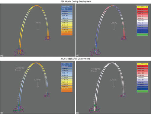
shows that during deployment, the deformation is most pronounced at the top and bottom of the frames. When only gravitational load is applied, the stress is mainly carried by the chord members. After deployment, the deformation is most pronounced at the top of the frames. And the horizontal thrust causes the stress concentration in the web members.
Figure 15. The FEA models during deployment(a)(b) and after deployment(c)(d).
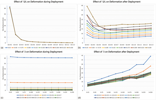
shows that during deployment, the rise-span ratio (S/L) has a negative correlation with the maximum displacement of the frames, yet the effect of the slenderness (λ) on the maximum displacement is very small. After deployment, both the rise-span ratio (S/L) and the slenderness (λ) influence the deformation of the frames. The correlation between rise-span ratio (S/L) and maximum deformation is negative when S/L is less than 0.5, and positive when S/L is greater than 0.5. The correlation between slenderness (λ) and maximum deformation is positive, which means that more web members are helpful to resist horizontal load and reduce deformation.
Figure 16. The effect of rise-span ratio(a)(b) and slenderness on max displacement(c)(d).
6.1.2. Overturning analysis
In this research, moment equilibria are used to investigate the relationship between the counterweight geometry and the anti-overturning stability of the frame. shows the critical state of overturning, and the moment equilibrium is expressed by
Figure 17. Parameters in the critical state of the overturning process.
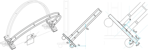
where is the balancing moment, and its value should be larger than
to prevent overturning.
,
denote the gravity of the counterweight and the frame,
,
denote the arms of the counterweight and frame, they are the horizontal distance between the centroids and the rotation center. The rotation center is located at the center of one wheel. Based on expression (4), the balancing moment can be written into three sets of expressions (5) with the length, width, and height of the balancing plate as variables.
The expression (6) and (7) shows that the critical value of the counterweight length is
, and indicates the positive quadratic relationship between
and the balancing moment when the counterweight length exceeds
. Similarly, expression (8) and (9) shows that the critical value of the counterweight height
is
, and indicates a positive quadratic relationship between
and the balancing moment when the counterweight height is smaller than
. Finally, expression (10) shows a positive linear relationship between the counterweight width
and the balancing moment when
is longer than zero.
In addition, for these slender and large-span structures proposed in this research, the vibration and serviceability problem should be considered carefully, meanwhile, a tuned mass damper (TMD) is a popular vibration absorber for these slender structures (Wang et al. Citation2021, Citation2022, Citation2023, Citation2023, Citation2023; Wang, Shi, and Zhou Citation2022; Wang, Zhou, and Shi Citation2023; Zhang, Wang, and Shi Citation2023).
6.2. Other aspects
6.2.1. Folding behavior
shows the folding process of the prototype, which has a central spiral unfolded shape and can be easily rotated into a compact planar volume when fully folded. The geometry of the frames and fabrics was optimized using the collision and stretch checking methods mentioned in 4.1. These methods effectively ensure the foldability of the prototype.
Figure 18. The folding process(a)-(f) and geometric comparison(g) of the prototype.
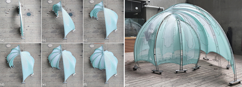
In addition, showcases the geometric control capability of CNC-knitted fabrics. The folding process is performed by pushing the frame without requiring additional positioning devices. The spatial relationship between the frames is determined solely by the tensioned fabric. The comparison of the field photo and wireframes from the design model reveals that the unfolded structure closely resembles the design geometry.
6.2.2. Manufacturing capabilities
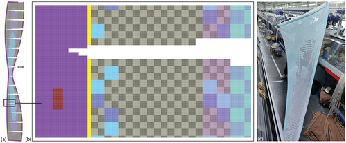
illustrates the knitting pattern and the resulting fabric of the prototype. The knitting pattern is generated using the method outlined in 5.2. The knitting path adapts to the fabric geometry and reduces the knitting width from 2085 needles to 955 needles, within the maximum knitting width of the machine. Intricate details such as tubes, holes, and three-color variations are integrated into the knitted fabric and knitted as a single piece. For instance, the purple pixels indicate spacer knit structures, which make the sleeves to insert the frames. The dark-red pixels indicate openings on the sleeves. The light and dark blue pixels in 8 × 8 modules depict large lace holes 1 cm in diameter using two plies of white yarns. The light and dark grey pixels in 4 × 4 modules depict small lace holes 0.5 cm in diameter using two plies of blue yarns. The light and dark purple modules depict small and large lace holes using one ply of blue yarn and one ply of white yarn, and so on. And in total, there are 20 colors and modules in each knitting pattern.
Figure 19. The knitting pattern(a)(b) and a piece of CNC-knitted fabric(c).
The frames are bent on an automatic three-roll bending machine. The radius and radians of the five frames are customized and vary from 1050 mm to 2280 mm and from to
. The frames adopt I-shaped sections, and horizontal crossbars are added at 400 mm intervals. The slenderness of the frames is set to 62.5 and the rise span ratios are set from 0.51 to 0.94 for stability.
7. Conclusion
The successful implementation of a full-scale prototype has demonstrated the effectiveness of the proposed system and related methods for realizing free-form deployable membrane structures. In comparison to alternative free-form deployable structures that utilize scissors, bending-active, folding, tensegrity, or inflatable components, the proposed system provides several remarkable benefits. Firstly, the system adopts unit composition, self-supporting components, and straightforward interactions between tension and compression members, so that it can retain geometric complexity while being simpler in terms of structural calculations, making it easier to implement for free-form applications. Secondly, the units can fold and unfold separately in the proposed system, resulting in a robust and practical deployment mechanism that can readily adapt to complex geometries and is simple to manage. Thirdly, the system relies on well-established manufacturing techniques such as CNC knitting and CNC bending, and these manufacturing techniques are well-suited for mass customization in architectural applications.
In conclusion, this research presents a novel deployable membrane system that streamlines the design process of free-form deployable membrane structures, allowing for smoother conversions of arbitrary free-form surfaces into deployable structural models, simpler kinematic analysis for free-form deployment, and reduced structural calculations of free-form deployable structures. The proposed system and associated methods contribute to the advancement of adaptive architectural and urban space design by expanding the design possibilities and application potentials of deployable membrane structures.
Acknowledgements
This research is funded by the Natural Science Foundation of Jiangsu Province (BK20220857), and the National Natural Science Foundation of China (No.52378008, No.52208008).
We would like to submit the enclosed manuscript entitled “Geometric Characteristics, Deployment Mechanisms, and Digital Fabrication Methods of a Free-Form Deployable Membrane System Based on CNC-knitted Fabrics and CNC-bent Frames” for consideration as an article of Journal of Asian Architecture and Building Engineering.
Disclosure statement
No potential conflict of interest was reported by the author(s).
Additional information
Funding
Notes on contributors
Yige Liu
Yige Liu was a postdoctoral researcher at the Department of Architecture, Southeast University, and is now an assistant professor at the College of Architecture and Urban Planning, Tongji University. Her research focuses on 3D knitting technologies, membrane materials, membrane structures, and their design potential for innovative lightweight building envelopes.
Yuchen Han
Yuchen Han is a postdoctoral researcher at the Department of Architecture, Southeast University. Her research focuses on structure design, structural teaching, and the collaboration between structure and space in architectural design.
Biao Li
Biao Li is a professor at the Department of Architecture in Southeast University, and the director of the Institute of Architectural Algorithms and Applications. His research focuses on architectural design and its theory, digital technology, generative design, and numerically controlled construction.
References
- Ahlquist, S., W. Mcgee, S. Sharmin. 2017. “PneumaKnit: Actuated Architectures Through Wale-And Course-Wise Tubular Knit-Constrained Pneumatic Systems.” ACADIA, Boston, 38–51.
- Ahlquist, S., A. Menges. 2013. “Frameworks for Computational Design of Textile Micro-Architectures and Material Behavior in Forming Complex Force-Active Structures[c].”ACADIA, Boston, 281–292.
- Attia, S. 2016. “Evaluation of Adaptive Facades: The Case Study of Al Bahr Towers in the UAE.” QScience Connect 2016 (2): 6. https://doi.org/10.5339/qproc.2016.qgbc.8.
- Blümel, D. 1972. Wandelbare Dächer. Stuttgart: Institute of Lightweight Structures.
- Blümel, D. 1975. IL 12 Wandelbare Pneus. Stuttgart: Institute of Lightweight Structures.
- Buckminster, F. R. 1962. Tensile-Integrity Structures. US Patent No. 3063521.
- Chandra, M., S. Kumar, S. Chattopadhyaya, S. Chatterjee, and P. Kumar. 2021. “A Review on Developments of Deployable Membrane-Based Reflector Antennas.” Advances in Space Research 68 (9): 3749–3764. https://doi.org/10.1016/j.asr.2021.06.051.
- Chen, T., J. Panetta, M. Schnaubelt, and M. Pauly. 2021. “Bistable Auxetic Surface Structures.” ACM Transactions on Graphics 40 (4): 1–9. Article 39. https://doi.org/10.1145/3450626.3459940.
- Ching, F. D. 2023. Architecture: Form, Space, and Order[m]. United Kingdom: Wiley.
- De Laet, L., R. Luchsinger, R. Crettol, M. Mollaert, and N. De Temmerman. 2009. “Deployable Tensairity Structures.” Journal of the International Association for Shell and Spatial Structures 50 (2): 121–128.
- Del Grosso, A. E., and P. Basso. 2013. “Deployable Structures.” Advances in Science and Technology (83): 122–131. https://doi.org/10.4028/www.scientific.net/ast.83.122.
- Dessi-Olive, J., J. Case, M. Koliner, V. Teja Meda. 2019. “Self-Deploying Tensegrity Structures with Inflatable Struts.” IASS annual symposia. Barcelona, No. 5, 1–8.
- De Temmerman, N. 2007. Design and Analysis of Deployable Bar Structures for Mobile Architectural Applications. Vrije Universiteit Brussel.
- Eisenbarth, C., W. Haase, Y. Klett, L. Blandini, and W. Sobek. 2021. “PAOSS: Pneumatically Actuated Origami Sun Shading.” Journal of Facade Design and Engineering 9 (9): 147–162.
- Escrig, F. 1996. “General Survey of Deployability in Architecture.” Mobile and Rapidly Assembled Structures 24: 3–22. https://doi.org/10.2495/MRS960011.
- Gantes, C. J. 2001. Deployable Structures: Analysis and Design. Southampton: WIT Press.
- Gupta, S. S., Y. Y. Tan, P. Z. Chia, C. P. Pambudi, Y. H. Quek, C. Yogiaman, and K. J. Tracy. 2020. “Prototyping Knit Tensegrity Shells: A Design-To-Fabrication Workflow.” SN Applied Sciences 2 (6): Article 1062. https://doi.org/10.1007/s42452-020-2693-4.
- Hanaor, A., and R. Levy. 2001. “Evaluation of Deployable Structures for Space Enclosures.” International Journal of Space Structures 16 (4): 211–229. https://doi.org/10.1260/026635101760832172.
- Hoberman, C. 2006. “Transformation in Architecture and Design.” Transportable Environments 3 (3): 70–79.
- Lienhard, J., N. Kugel. 2015. “Design of a Retractable Membrane Roof in Buchs CH.” IASS Annual Symposia, Amsterdam, No. 27, 1–10.
- Melancon, D., B. Gorissen, C. J. García-Mora, C. Hoberman, and K. Bertoldi. 2021. “Multistable Inflatable Origami Structures at the Metre Scale.” Nature 592 (7855): 545–550. https://doi.org/10.1038/s41586-021-03407-4.
- Mollaert, M. 1996. “Retractable Membrane Roofs.” WIT Transactions on the Built Environment 24: 407–417. https://doi.org/10.2495/MRS960381.
- Narayanan, V., L. Albaugh, J. Hodgins, S. Coros, and J. Mccann. 2018. “Automatic Machine Knitting of 3D Meshes.” ACM Transactions on Graphics 37 (3): 1–15. Article 35. https://doi.org/10.1145/3186265.
- Otto, F. 1973. Tensile Structures; Design, Structure, and Calculation of Buildings of Cables, Nets, and Membranes. Cambridge: The MIT Press.
- Panetta, J., F. Isvoranu, T. Chen, E. Siéfert, B. Roman, and M. Pauly. 2021. “Computational Inverse Design of Surface-Based Inflatables.” ACM Transactions on Graphics 40 (4): 1–14. https://doi.org/10.1145/3450626.3459789.
- Pellegrino, S. 2001. Deployable Structures[m]. Vienna: Springer.
- Perez, P. E. 1965. Three Dimensional Reticular Structure. US Patent No. 3185164.
- Pillwein, S., and P. Musialski. 2021. “Generalized Deployable Elastic Geodesic Grids.” ACM Transactions on Graphics 40 (6): 1–15. Article 271. https://doi.org/10.1145/3478513.3480516.
- Popescu, M., M. Rippmann, A. Liew, L. Reiter, R. J. Flatt, T. Van Mele, and P. Block. 2021. “Structural Design, Digital Fabrication and Construction of the Cable-Net and Knitted Formwork of the KnitCandela Concrete Shell.” Structures 2020:1287–1299. https://doi.org/10.1016/j.istruc.2020.02.013.
- Popescu, M., M. Rippmann, T. Van Mele, and P. Block. 2017. Design Modeling Symposium, Paris, 271–284.
- Preisinger, C., and M. Heimrath. 2014. “Karamba-A Toolkit for Parametric Structural Design.” Structural Engineering International 24 (2): 217–221. https://doi.org/10.2749/101686614X13830790993483.
- Ren, Y., U. Kusupati, J. Panetta, F. Isvoranu, D. Pellis, T. Chen, and M. Pauly. 2022. “Umbrella Meshes: Elastic Mechanisms for Freeform Shape Deployment.” ACM Transactions on Graphics 41 (4): 1–15. Article 152. https://doi.org/10.1145/3528223.3530089.
- Rieffel, J., F. Valero-Cuevas, and H. Lipson. 2009. “Automated Discovery and Optimization of Large Irregular Tensegrity Structures.” Computers & Structures 87 (5–6): 368–379. https://doi.org/10.1016/j.compstruc.2008.11.010.
- Riether, G., A. J. Wit, S. T. Putt. 2015. “The Underwood Pavilion: An Investigation in Parametric Tensegrity Structures.” CAADRIA, Daegu, 663–672.
- Roovers, K., L. A. Mira, N. De Temmerman. 2013. “From Surface to Scissor Structure.” Proceedings of the First Conference Transformables, Munich, 275–280.
- Roovers, K., N. D. Temmerman. 2015. “Digital Design of Deployable Scissor Grids Based on Circle Packing.” IASS annual symposia, Amsterdam, No. 6, 1–12.
- Rose, K., A. Sheffer, J. Wither, M. P. Cani, B. Thibert. 2007. “Developable Surfaces from Arbitrary Sketched Boundaries[c].” Proceedings of the fifth Eurographics symposium on Geometry processing, Barcelona, Spain, 163–172.
- Schek, H. J. 1974. “The Force Density Method for Form Finding and Computation of General Networks. Computer Methods in Applied Mechanics and Engineering.” Computer Methods in Applied Mechanics and Engineering 3 (1): 115–134. https://doi.org/10.1016/0045-7825(74)90045-0.
- Skouras, M., B. Thomaszewski, P. Kaufmann, A. Garg, B. Bickel, E. Grinspun, and M. Gross. 2014. “Designing Inflatable Structures.” ACM Transactions on Graphics 33 (4): 63. https://doi.org/10.1145/2601097.2601166.
- Tachi, T. 2012. “Interactive Freeform Design of Tensegrity.” Advances in Architectural Geometry, Paris, 259–268. https://doi.org/10.1007/978-3-7091-1251-9_21.
- Tamke, M., Y. Sinke Baranovskaya, F. Monteiro, J. Lienhard, R. La Magna, and M. Thomsen. 2020. “Computational Knit – Design and Fabrication Systems for Textile Structures with Customised and Graded CNC Knitted Fabrics.” Architectural Engineering and Design Management 17 (3–4): 175–195. https://doi.org/10.1080/17452007.2020.1747386.
- Thomsen, M. R., Y. S. Baranovskaya, F. Monteiro, J. Lienhard, R. L. Magna, M. Tamke. 2019. “Systems for Transformative Textile Structures in CNC Knitted Fabrics–Isoropia[c].” Proceedings of the TensiNet Symposium, Milan, 95–110.
- Tracy, K., S. Gupta, Y. Stella, S. Wen, T. Wortmann, R. Bamford. 2019. “Tensile Configurations: Exploring Spatial Membrane Tensegrity Shell Structures.” ACADIA, Austin, 110–119.
- Tracy, K., S. S. Gupta, T. Ying Yi, C. Pei Zhi, Q. Yu Han, R. Bamford, C. Yogiaman, O. Weeger 2019. “Knit Tensegrity Shell.” IASS Annual Symposium, Barcelona, No. 5, 1–9.
- Wang, L., S. Nagarajaiah, W. Shi, and Y. Zhou. 2021. “Semi-Active Control of Walking-Induced Vibrations in Bridges Using Adaptive Tuned Mass Damper Considering Human-Structure-Interaction.” Engineering Structures 244:112743. https://doi.org/10.1016/j.engstruct.2021.112743.
- Wang, L., S. Nagarajaiah, W. Shi, and Y. Zhou. 2022. “Seismic Performance Improvement of Base-Isolated Structures Using a Semi-Active Tuned Mass Damper.” Engineering Structures 271:114963. https://doi.org/10.1016/j.engstruct.2022.114963.
- Wang, L., S. Nagarajaiah, Y. Zhou, and W. Shi. 2023. “Experimental Study on Adaptive-Passive Tuned Mass Damper with Variable Stiffness for Vertical Human-Induced Vibration Control.” Engineering Structures 280:115714. https://doi.org/10.1016/j.engstruct.2023.115714.
- Wang, L., W. Shi, and Y. Zhou. 2022. “Adaptive-Passive Tuned Mass Damper for Structural Aseismic Protection Including Soil–Structure Interaction.” Soil Dynamics and Earthquake Engineering 158:107298. https://doi.org/10.1016/j.soildyn.2022.107298.
- Wang, L., Y. Zhou, S. Nagarajaiah, and W. Shi. 2023. “Bi-Directional Semi-Active Tuned Mass Damper for Torsional Asymmetric Structural Seismic Response Control.” Engineering Structures 294:116744. https://doi.org/10.1016/j.engstruct.2023.116744.
- Wang, L., Y. Zhou, and W. Shi. 2023. “Seismic Control of a Smart Structure with Semiactive Tuned Mass Damper and Adaptive Stiffness Property.” Earthquake Engineering and Resilience 2 (1): 74–93. https://doi.org/10.1002/eer2.38.
- Wang, L., Y. Zhou, W. Shi, and Y. Zhou. 2023. “Seismic Response Control of a Nonlinear Tall Building Under Mainshock-Aftershock Sequences Using Semi-Active Tuned Mass Damper.” International Journal of Structural Stability and Dynamics. https://doi.org/10.1142/S0219455423400278.
- Wu, K., H. Swan, and C. Yuksel. 2019. “Knittable Stitch Meshes.” ACM Transactions on Graphics 38 (1): 1–13. Article 10. https://doi.org/10.1145/3292481.
- Wyller, M., M. Yablonina, M. Alvarez, and A. Menges. 2020. “Adaptive Kinematic Textile Architecture.” Construction Robotics 4 (3): 227–237. https://doi.org/10.1007/s41693-020-00046-5.
- Yang, S., and C. Sultan. 2016. “Modeling of Tensegrity-Membrane Systems.” International Journal of Solids and Structures 82:125–143. https://doi.org/10.1016/j.ijsolstr.2015.09.012.
- Yige, L., L. Li, Y. Philip. 2019. “A Computational Approach for Knitting 3D Composites Preforms.” CDRF, Shanghai, 232–246.
- Zhang, X., R. Nie, Y. Chen, and B. He. 2021. “Deployable Structures: Structural Design and Static/Dynamic Analysis.” Journal of Elasticity 146 (2): 199–235. https://doi.org/10.1007/s10659-021-09860-6.
- Zhang, H., L. Wang, and W. Shi. 2023. “Seismic Control of Adaptive Variable Stiffness Intelligent Structures Using Fuzzy Control Strategy Combined with LSTM.” Journal of Building Engineering 78:107549. https://doi.org/10.1016/j.jobe.2023.107549.
- Zheng, C., T. Sun, X. Chen. 2016. “Deployable 3D Linkages with Collision Avoidance.” Symposium on Computer Animation, Zurich, 179–188.