
 ?Mathematical formulae have been encoded as MathML and are displayed in this HTML version using MathJax in order to improve their display. Uncheck the box to turn MathJax off. This feature requires Javascript. Click on a formula to zoom.
ABSTRACT
Based on a new type of isolated structure, this paper studies the seismic response of the structure under single mainshock and mainshock-aftershock sequences. The new structure developed from the base-isolated structure and the inter-storey isolated structure. To compare its seismic performance with a fixed-base structure, a new staggered storey isolated structure model is developed using ETABS software. The results indicate that during both single mainshock and mainshock-aftershock sequences, the maximum inter-storey displacement of the staggered storey isolated structure is concentrated in the isolated layer, while the stress damage of the core tube mainly occurs between the upper and lower isolated layers. Under mainshock-aftershock sequences, the displacement of the isolated layer is larger than that under the single mainshock, and the distribution of plastic hinges of the frame is greater than that under the single mainshock, compared with the single mainshock sequences, the stress distribution of the core tube and the inter-story displacement of the structure increase by 19.80% anc23%% respectively. Consequently, the damage to the structure under mainshock-aftershock sequences is more severe. The hysteresis curve of the upper isolated layer bearings is more pronounced and demonstrates better energy absorption than that of the lower isolated layer bearings. Overall, the staggered storey isolated structure exhibits better seismic performance than the fixed-base structure. The isolated effectiveness and energy dissipation of the new staggered storey isolated structure improve when the upper isolated layer is lowered.
1. Introduction
The new staggered storey isolated structure is a new type of structure developed from the base-isolated structure and the inter-storey isolated structure. Comparison of the three structures is shown in . Due to its flexible isolated arrangement, it has been applied in various engineering projects. One notable project that uses the new staggered storey isolated structure is the Baotou Huafa Xintiandi Project (Zhang et al. Citation2021). This project serves as a representative example of the new structure, with the lower isolated layer located at the bottom of the core tube and the upper isolated layer located at the third layer of the frame. Zhang et al. (Liu et al. Citation2022; Zhang et al. Citation2022)conducted damage analysis on the new staggered storey isolated structure and found that the structure had good shock absorption performance and slight damage.
Figure 1. Comparison diagram of the three structures:(a) base isolated structure, (b) inter-storey isolated structure, (c) new staggered storey isolated structure (blank area represents frame, black shaded area represents isolated bearings).
A large number of seismic damage data show that when an earthquake occurs, it may be accompanied by many aftershocks, and the damage caused by aftershocks to the structure cannot be ignored. Usually, the interval between the mainshock and the aftershock is not long, and the magnitude of the aftershock is smaller than the mainshock. In 1999, the Chi-Chi earthquake in Taiwan, China (Wang et al. Citation2016) occurred five strong aftershocks within one week after the mainshock of magnitude 7.6. In 2008, the Wenchuan earthquake occurred in Sichuan, China (Chen Citation2009). Within nearly 20 days after the mainshock of magnitude 8.0, five strong aftershocks of magnitude 6.0 or above occurred. In 2014, a mainshock with a magnitude of 8.2 occurred in northern Chile (Sheng et al. Citation2015), followed by a strong aftershock of magnitude 7.6. Kaitong Wu et al (Wu et al. Citation1987). discovered the hazards of aftershocks and strong aftershocks, and their research on the impact of ground motion on the structure under the mainshock-aftershocks sequences was the first in China. Jieya Liu et al (Liu et al. Citation2021). analyzed the damage to the base-isolated structure of the mainshock-aftershock sequences, and the damage caused by the aftershock was more prominent. Ruilong Han et al (Han et al. Citation2014). researched on reducing the risk of earthquakes by base-isolated structures, considering that the seismic risk will lead to a higher degree of damage under the mainshock-aftershock sequences. In the collapse analysis of structures under the mainshock-aftershock ground motion, aftershocks increase the probability of collapse (Li et al. Citation2014). Fabio Mazza (Mazza and Labernarda Citation2020) found that the magnetic damping linkage could reduce the internal impact of the earthquake on the base-isolated structure, and the effect of the acceleration pulse on the fixed base and base-isolated structure (Mazza and Labernarda Citation2022). Weinong Shu et al(W., S. et al. Citation2021). through elastic-plastic analysis of structures, adopted inter-storey isolated technology in high-intensity regions to effectively ensure the seismic performance of structures. Fulin Zhou et al (Zhou et al. Citation2009). found that the lower the location of the isolated layer, the more obvious the shock absorption effect of the superstructure by optimizing the parameters of the inter-story isolated structure. Liangkun Wang used tuned mass damper to study the acceleration, displacement response and structural damage of the structure, and found that it can effectively alleviate the earthquake and has low seismic efficiency (Wang et al. Citation2019a, Citation2019b, Citation2020, Citation2020a, Citation2023c). The large chassis and multiple tower-layer structure can greatly reduce the seismic response of the structure and effectively improve the seismic safety of the structure (Liu et al. Citation2020). Xiaohui Yu (Yu et al. Citation2022) selected 533 real mainshock-aftershock sequences as input, and the incremental damage caused by aftershocks to the mainshock damage structure is strong. Youfa Yang et al (Yang et al. Citation2019). used an incremental dynamic analysis method to analyze the damage of the step-terrace structure under mainshock-aftershock sequences with parameters of Park-Ang damage index and ground motion intensity. Fabio Mazza (Mazza Citation2021) studied a hospital and found that base-isolated structures are less prone to collapse. Liangkun Wang et al. found that tuned mass damper can effectively improve the seismic effect of the structure by studying the base-isolated structure (Wang et al. Citation2022, Citation2023b). Weiping Wen (Wen Citation2011) studied the single degree of freedom system of mainshock-aftershock sequences ground motion and found that the hysteretic energy dissipation of the structure under the aftershock continued action increased compared with that under the single mainshock. The maximum inter-storey displacement angle, maximum residual the inter-layer displacement angle and top displacement are used to reflect the influence of mainshock-aftershock on structure (Mao and Chang Citation2019; Wang Citation2017; Wang and Zhang Citation2022). Liangkun Wang et al. carried out nonlinear analysis of high-rise structures and found that tuned mass damper had a significant effect under strong aftershocks than mainshocks (Wang et al. Citation2023a). In the future study, the structural control devices and energy dissipation dampers will be investigated (Wang and Nagarajaiah Citation2023, Citation2023; Wang et al. Citation2020b, Citation2021).
At present, the seismic design of buildings in the code basically adopts a single mainshock, and the cumulative damage effect of mainshock-aftershock ground motion on the structure is not fully considered. There are few research results on the response analysis of the new staggered storey isolated structure under the mainshock-aftershocks sequences. Based on this, this paper establishes a new staggered storey isolated structure and studies the seismic response analysis of the structure under the single mainshock and mainshock-aftershock sequences.
2. Structural modeling
2.1. Project overview
A 24-story frame-core tube new staggered isolated structure is established. The height of the bottom floor is 4.5 m, the height of the standard floor is 3.6 m, the total height is 83.3 m, the building plan size is 29.4 m × 26.4 m, and the aspect ratio is 3.1. The lower isolated layer is located at the bottom of the structure, the upper isolated layer is located between the 8th and 9th floor of the structure, with a height of 1.6 m. This building is located in the seismic fortification intensity of 8 degrees, the site category is class II, the site characteristic period is 0.40 s and the damping ratio is 0.05. The basic seismic acceleration is 0.20 g., The seismic design of the structure meets the requirements of the GB 50,011–2010 Code for Seismic Design of Buildings (GB 5Citation2016). The concrete strength grade of the column and beam is C40, and the steel material is HRB400. The elevation and plan of the frame-core tube staggered storey isolated high-rise building structure are shown in , and the section information of the column and beam is shown in .
Figure 2. Schematic diagram of the new staggered storey isolated structure.
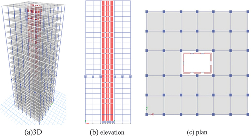
Table 1. Section size parameters.
2.2. Modeling information
Based on the finite element software ETABS, a new high-rise staggered storey isolated structure model is established. The bottom two floors of the core tube are reinforced area by layered shell with a thickness of 250 mm, the non-bottom strengthening area is simulated by an elastic thin shell element. In the definition of elastic-plastic conditions, the P-Δ effect is set to perform geometric nonlinear iterative calculation. C40 concrete adopts Takeda element and HRB400 steel adopts Kinematic element. The stress-strain curves are shown in . The fiber PMM hinges are used in the frame columns, and the M3 hinges are used at both ends of the frame beams and coupling beams. The plastic hinge curve is shown in . The isolated bearing used in the structure is lead rubber bearing. The relationship between the force and displacement of the support is shown in . Direct integration method is used for dynamic time history analysis. The parameters of the isolated bearing are shown in .
Figure 3. Material stress-strain curve: (a) concrete; (b) steel.
Figure 4. Plastic hinge curve (IO immediate occupancy; LS life safety; CP collapse prevention).
Figure 5. Force-displacement relationship of LRB.
Table 2. Bearing parameters.
3. Ground motions
The ground motion should be selected from natural ground motion and artificial tectonic constructed ground motion. The mainshock and aftershock ground motion are derived from the NGA-West2 ground motion database of the Pacific Earthquake Engineering Research Center (PEER) (Ancheta and Stewart Citation2014). Although more than one aftershock usually occurs after a real earthquake, only one aftershock is considered after each mainshock in this study. The selection principle is listed as follows:
The mainshock-aftershock ground motion records are selected from the same platform.
The magnitude of the selected mainshock-aftershock ground motion satisfies: Mw ≥5.0.
The peak ground acceleration (PGA) of the selected mainshock-aftershock ground motion satisfies: PGA ≥0.04 g.
The available frequency of the selected mainshock-aftershock ground motion satisfies: Fz ≤1 Hz.
The selected mainshock-aftershock ground motion information is shown in .
Table 3. Detailed information of the mainshock-aftershock ground motion sequences.
In the nonlinear analysis of the structure, the mainshock and aftershock were recorded to form a ground motion sequence. A period of time interval is added between the mainshock and the aftershock (Hatzigeorgiou and Beskos Citation2009) to ensure that the free vibration of the structure is restored to a new equilibrium after the mainshock damage, allowing enough time to improve the seismic response and achieve better results. According to the attenuated method (Yu et al. Citation2019)aftershock records are selected based on the statistical relationship between the mainshock and aftershock intensities, as well as the predictions of the attenuation model. The Peak Ground Acceleration (PGA) of the mainshock is greater than the PGA of the aftershock. In this paper, the time interval of 60s (Yu et al. Citation2022) between the mainshock and aftershock is used as the input ground motion for calculation. The time history analysis of the structure in rare earthquakes is carried out, and the PGA of the mainshock is uniformly adjusted to 0.4 g. The aftershock amplitude is adjusted proportionally. The combination mode of ground motion under mainshock-aftershock sequences is shown in . The time history response spectrum of the mainshock-aftershock sequences is shown in .
Figure 6. Acceleration time history of the mainshock-aftershock earthquake sequence.
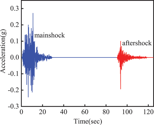
Figure 7. Response spectrum curve of mainshock-aftershock sequences.
4. Structural response analysis under mainshock-aftershock sequences
4.1. Structural period
presents a comparison of the top three isolated periods between the fixed-base structure and the new staggered storey isolated structure. It is evident that the isolation period of the new staggered storey isolated structure is significantly longer than that of the fixed-base structure, which is beneficial for mitigating the seismic response of the structure. The average response spectrum of both structures is consistent with the design response spectrum.
Table 4. Period comparison before and after isolated.
4.2. Inter-storey displacement
A nonlinear analysis is carried out under earthquake conditions, and the comparison of inter-storey displacement between the new staggered storey isolated structure and the fixed-base structure is shown in .
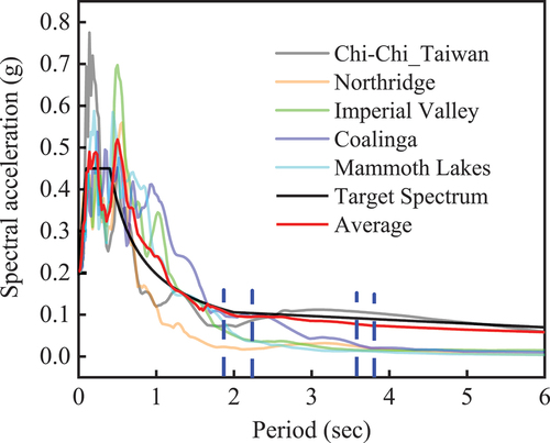
Figure 8. Inter-storey displacement of the new staggered storey isolated structure: (a) single mainshock; (b) mainshock-aftershock.
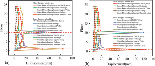
Figure 9. Inter-storey displacement of the fixed-base structure: (a) single mainshock; (b) mainshock-aftershock.

The core tube of the new staggered story isolated structure is separated from the frame below the upper isolated layer, while the core tube and the frame above the upper isolated layer are integrated. As shown in , when subjected to single mainshock and mainshock-aftershock sequence, the inter-storey displacement of the structure is concentrated mainly in the upper and lower isolated layers, with the displacement of the frame below the upper isolated layer is greater than that above it, and the displacement of the frame below the upper isolation layer is greater than that of the core tube. Moreover, the frame displacement below the upper isolated layer is 1.2 times that above the upper isolation layer. The isolated layer exhibits more pronounced variations in inter-storey displacement under mainshock-aftershock sequences than under single mainshock events. In contrast, the inter-storey displacement of the non-isolated layer changes only slightly.
depicts the inter-storey displacement of the fixed-base structure, which is observed to be greater than that of the new staggered storey isolated structure. Thus, the seismic performance of the fixed-base structure is inferior to that of the new staggered storey isolated structure. The inter-story displacement of the two structures under the mainshock-aftershock sequence is 23% higher than that under the single mainshock.
The new staggered storey isolated structure is arranged with the lower isolated layer and the upper isolated layer. The displacement comparison of isolated layer under the single mainshock and mainshock-aftershock sequences is shown in .
Figure 10. Displacement comparison of staggered isolated bearings under mainshock-aftershock sequences.
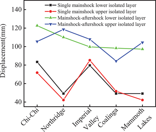
It can be seen from that the displacement of isolated layer under mainshock-aftershock sequences is about twice that of isolated layer under single mainshock. The maximum inter-storey displacement of the structure is mainly concentrated in the isolated layer, and the isolated bearings play a good isolated effect. Generally, the magnitude of aftershocks is smaller than that of the single mainshock, and the cumulative damage to the structure caused by aftershocks is more serious. Therefore, attention should be paid to the impact of aftershocks on the structure.
4.3. Different locations of the upper isolation layer
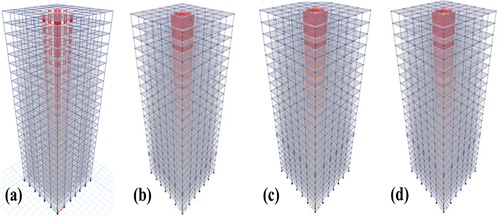
To investigate the impact of varying staggered layer location on the seismic response of the new staggered storey isolated structure, four different models were developed. These models incorporated the upper isolated layer at different elevations, namely the 1rd floor (Model 1), 3rd floor (Model 2), 6th floor (Model 3) and 8th floor (Model 4). The corresponding models are illustrated in .
Figure 11. New staggered layer isolated structure with different isolated layers: (a)the 1rd floor (base isolated structure), (b) the 3rd floor, (c) the 6rd floor, (d) the 8rd floor.
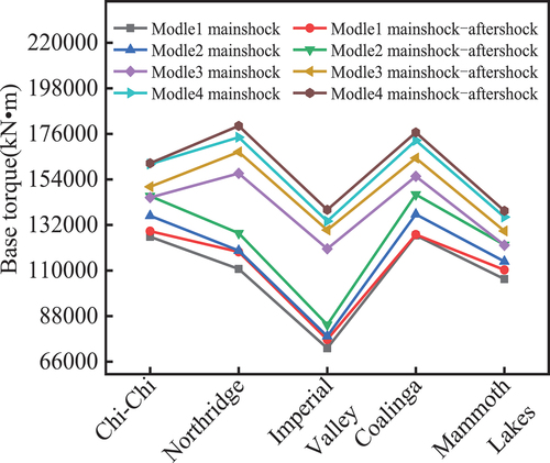
The base shear is a crucial parameter for seismic safety design of a building, representing the maximum horizontal force acting on the structure during an earthquake. show the base shear and base torque of the new staggered storey isolated structure with different locations of the upper isolated layer (Model 1-base isolated structure, Model 2, Model 3 and Model 4). In all four models, the base shear and base torque under mainshock-aftershock sequences are higher than those under a single mainshock. In , as the location of the upper isolated layer decreases, the base shear force and base torque show a downward trend, decreasing by 10.5 % to 28.4 %. The base shear force and base torque of Model 1 are the lowest. This is because Model 1 is fully equipped with isolated bearings at the bottom of structure, whereas the other three structures are equipped with isolated bearings only at the core tube position at the bottom of structure.
Figure 12. Base shear at different locations of upper isolated layer.
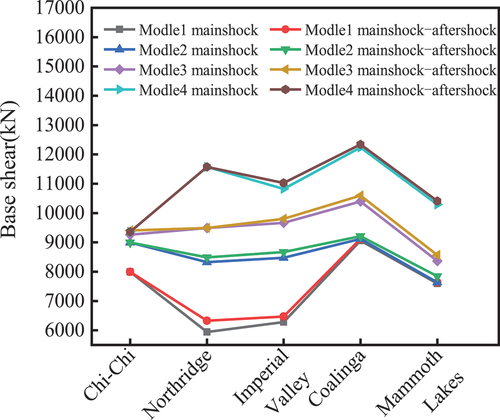
Figure 13. Base torque at different locations of upper isolated layer.
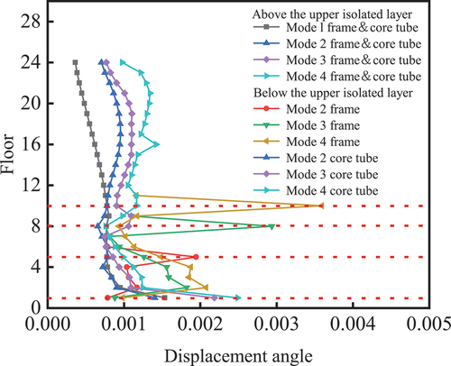
shows the inter-layer displacement angle of the new staggered storey isolated structure models with different locations of the upper isolated layer (Model 1, Model 2, Model 3 and Model 4). Under the action of single mainshock and mainshock-aftershock, the interlayer displacement angle of several models changes with the change of the position of the upper isolated layer. As the location of the upper isolation layer decreases, and the corresponding inter-layer displacement angle goes down.
Figure 14. Inter-layer displacement angle at different locations of upper isolated layer.
4.4. Checking calculation of bearing capacity and deformation of isolated bearing
Through seismic time-history analysis, the bearing capacity of isolated bearing under ground motion is checked. The stress and the maximum horizontal deformation of the isolated bearings are shown in .
Table 5. Stress and deformation of isolated bearings.
According to the requirements of seismic code, the vertical compressive stress of the isolated bearing should not be greater than 30MPa, the tensile stress should not be greater than 1MPa. The horizontal deformation should not be greater than 0.55 times the diameter of the 800 mm rubber bearing and three times the total thickness of the rubber layer, with the minimum value of these two criteria being selected. Through analysis, the maximum compressive stress of the isolated bearing is 19.78MPa and the maximum tensile stress of the bearing is 0.75 MPa under the single mainshock. Under mainshock-aftershock sequences, the maximum compressive stress of the isolated bearing is 19.99 MPa, the maximum tensile stress is 0.79 MPa, and the maximum horizontal deformation is 395 mm, all of which meet the requirements of the specification.
4.5. Comparison of structural internal force damage under mainshock-aftershock sequences
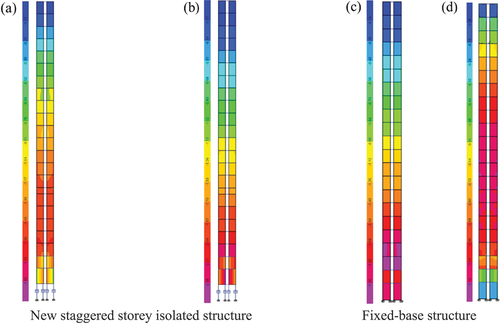
The distribution of stress damage in the core tube is shown in . According to the diagram, the stress distribution of the core tube of the new staggered storey isolated structure under the mainshock-aftershock sequences is mainly concentrated between the upper isolated layer and the lower isolated layer. The damage to the core tube below the upper isolated layer is more serious than that to the upper-structure. The stress distribution of the fixed-base structure is concentrated in the bottom floors under the single mainshock, and the stress damage is distributed throughout the structure under the mainshock-aftershock sequences. Under the action of mainshock-aftershock, the stress distribution of the core tube of the new staggered storey isolated structure and the base isolated structure is 19.80 % and 41.58 % higher than that under the mainshock alone.
Figure 15. Stress distribution in core tube influences force: single mainshocks (a) and (c); mainshock-aftershocks (b) and (d).
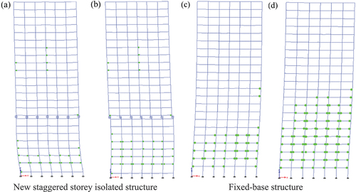
The distribution of plastic hinges in the frame, as shown in , reveals that the fixed-base structure has more frame plastic hinges than the new staggered storey isolated structure. This indicates that the fixed-base structures are more susceptible to damage than the new staggered storey isolated structure under the mainshock-aftershock sequences.
Figure 16. Distribution of frame plastic hinge: single mainshocks (a) and (c); mainshock-aftershocks (b) and (d).
illustrates the hysteretic curves of the frame isolated bearing and the core tube isolated bearing under both single mainshock and mainshock-aftershock sequences. As shown, the hysteresis curve of the isolated bearings connected to the frame column is more complete under the mainshock-aftershock sequences than under the single mainshock. However, the hysteresis curve of the lower isolated layer shows little change in response to the mainshock-aftershock sequences. further shows that the hysteretic curve of the upper isolated layer bearings is significantly more complete than that of the lower isolated layer bearings under the single mainshock.
Figure 17. Hysteresis curve of isolated bearing under single mainshock and mainshock-aftershock sequences: (a) the upper isolated layer bearing; (b) the lower isolated layer bearing.
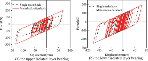
Figure 18. Hysteretic curves of upper and lower isolated layer bearings: (a) single mainshock; (b) mainshock-aftershock.
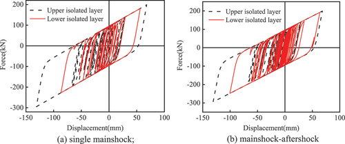
The difference in hysteretic behavior between the bearings of the upper and lower isolated layers is not significant under mainshock-aftershock sequences. However, the bearings of the upper isolated layer exhibit better seismic performance and energy absorption compared to those of the lower isolated layer. Therefore, the corner bearings of both the upper and lower isolated layer bearings are selected, as these are subjected to the largest damage and displacement deformation, and the energy dissipation curve area of the bearing is larger.
5. Conclusion
A frame-core tube structure model of a high-rise building was established, and an overall nonlinear time history analysis of the new staggered storey isolated structure was performed under the mainshock-aftershock sequences. The following conclusions were drawn:
Under both the single mainshock and mainshock-aftershock sequences, the maximum inter-storey displacement of the new staggered storey isolated structure is concentrated in the isolated layer, and the displacement of the frame below the upper isolation layer is 20% higher than that of the frame above the upper isolation layer. The displacement of the isolated layer under the mainshock-aftershock sequences is twice that of the isolated layer under the single mainshock.
The hysteresis curve of the bearings in the upper isolated layer is complete, and their energy dissipation is better than that of the bearings in the lower isolated layer.
Under the mainshock-aftershock sequences, there are more plastic hinges in the frame than under the single mainshock, the stress distribution of the core tube of the new staggered storey isolated structure increases by 19.80% compared with that under the single mainshock sequences. The damage of the structure is more severe under the mainshock-aftershock sequences.
The seismic performance of the new staggered storey isolated structure is better than that of the fixed-base structure.
The lower the position of the upper isolated layer in the new staggered storey isolated structure, the lower the base shear base torque and the inter-story displacement angle by 10.5% ~ 28.4%, and the better the isolated effect and energy dissipation of the structure.
Declaration of conflicting interests
The authors declared no potential conflicts of interest with respect to the research, authorship and publication of this article.
Acknowledgements
The writers gratefully acknowledge the financial support of National Natural Science Foundation of China (No.52168072, No.51808467), High-level Talents Support Plan of Yunnan Province, China (2020). The corresponding author is Dewen Liu and the email is [email protected].
Disclosure statement
No potential conflict of interest was reported by the authors.
Additional information
Funding
Notes on contributors
Qianqian Wu
Qianqian Wu, female, postgraduate, mainly engaged in structural isolation and shock absorption research.
Dewen Liu
Dewen Liu, corresponding author, male, doctor, professor, mainly engaged in structural isolation and shock absorption research.
Tiange Zhao
Tiange Zhao, female, postgraduate, mainly engaged in structural isolation and shock absorption research.
Yanping Zheng
Yanping Zheng, female, postgraduate, mainly engaged in structural isolation and shock absorption research.
Yuan Zhang
Yuan Zhang, male, postgraduate, mainly engaged in structural isolation and shock absorption research.
Min Lei
Min Lei, male, doctor, mainly engaged in steel structure and composite structure research.
References
- Ancheta, T. D., and J. P. Stewart. 2014. “NGA-West2 Database.” Earthquake Spectra 3 (30): 989-1005.
- Chen, H. 2009. “Reflections on Seismic Safety of Dams After Wenchuan Earthquake.” Engineering Science 11 (6): 44–53.
- GB 50011-2010. 2016. Code for Seismic Design of Buildings. Beijing: China Architecture & Building Press.
- Han, R., Y. Li, and van de Lindt J. 2014.“ Seismic Risk of Base Isolated Non-Ductile Reinforced Concrete Buildings Considering Uncertainties and Mainshock-Aftershock Sequences.” Structural Safety 50:39–56. https://doi.org/10.1016/j.strusafe.2014.03.010.
- Hatzigeorgiou, G. D., and D. E. Beskos. 2009. “Inelastic Displacement Ratios for SDOF Structures Subjected to Repeated Earthquakes.” Engineering Structures 31 (11): 2744–2755. https://doi.org/10.1016/j.engstruct.2009.07.002.
- Li, Y., M. ASCE, Song R, and Van De Lindt JW. 2014. “Collapse Fragility of Steel Structures Subjected to Earthquake Mainshock-Aftershock Sequences.” Journal of Structural Engineering 140 (12): 04014095. https://doi.org/10.1061/(ASCE)ST.1943-541X.0001019.
- Liu, J., and X. Huang. 2021. “Seismic Damage of Base-Isolated Structure Under Main Shock-Aftershock Sequence.” Journal of Vibration, Measurement & Diagnosis 41 (6): 1052–1058+1232. https://doi.org/10.16450/j.cnki. issn.1004⁃6801.2021.06.002.
- Liu, F., S. Lin, and Zhonghai H. 2020. “Structural Scheme Selection and Design of an Isolated High-Rise Building Structure with a Large Chassis and Multiple Tower-Layer in a High-Intensity Region.” Building Structure 50 (10): 83–89+66. https://doi.org/10.19701/j.jzjg.2020.10.011.
- Liu, D., L. Li, Zhang Y, Chen L, Wan F, and Yang F. 2022. “Study on Seismic Response of a New Staggered Story Isolated Structure Considering SSI Effect.” Journal of Civil Engineering and Management 28 (5): 397–407. https://doi.org/10.3846/jcem.2022.16825.
- W., S., Lu, Q. 2021.“Research on Interlayer Isolation Design of Subway Superstructure in High Seismic Intensity Region.” Building Structure 51 (19): 72–76+71. https://doi.org/10.19701/j.jzjg.2021.19.013.
- Mao, C., and X. Chang. 2019. “Shake Table Tests of a Self-Centering Rc Frame Structure Under Mainshock-Aftershock Ground Motions.” Journal of Natural Disasters 28 (4): 1–12. https://doi.org/10.13577/j.jnd.2019. 0401.
- Mazza, F. 2021. “Base-Isolation of a Hospital Pavilion Against In-Plane-Out-Of-Plane Seismic.” Engineering Structures 228:111504. https://doi.org/10.1016/j.engstruct.2020.111504.
- Mazza, F., and R. Labernarda. 2020. ““Magnetic Damped Links to Reduce Internal Seismic Pounding in Base‑Isolated Buildings.” Bulletin of Earthquake Engineering 18 (15): 6798–6824. https://doi.org/10.1007/s10518-020-00961-6.
- Mazza, F., and R. Labernarda. 2022. “Effects of Near-Fault Acceleration and Non-Acceleration Pulses on Pounding Between In-Plan Irregular Fixed-Base and Base-Isolated Buildings.” Structural Control & Health Monitoring. https://doi.org/10.1002/stc.2992.
- Sheng, S., Y. Wan, and Huang JZ. 2015. “Primary Research on the 2014 MS8.2 Chile Earthquake Triggering by Large Earthquake Occurred on the Boundary of South American Plate Since 2000.” Earthquake Research in China 31 (3): 501–509.
- Wang, B. 2017. Multivariate Joint Fragility and Probabilistic Safety Prediction of RC Frame Structures Under Mainshock-Aftershock Sequence, Harbin Institute of Technology. Harbin: Master of engineering.
- Wang, L., and S. Nagarajaiah. 2023. “Experimental Study on Adaptive-Passive Tuned Mass Damper with Variable Stiffness for Vertical Human-Induced Vibration Control.” Engineering Structures 280. https://doi.org/10.1016/J.ENGSTRUCT.2023.115714.
- Wang, L., S. Nagarajaiah, Shi W, and Zhou Y. 2020. “Study on Adaptive-Passive Eddy Current Pendulum Tuned Mass Damper for Wind-Induced Vibration Control.” The Structural Design of Tall & Special Buildings 29:15. https://doi.org/10.1002/tal.1793.
- Wang, L., S. Nagarajaiah, Shi W, and Zhou Y. 2021. “Semi-Active Control of Walking-Induced Vibrations in Bridges Using Adaptive Tuned Mass Damper Considering Human-Structure-Interaction.” Engineering Structures 244:112743. https://doi.org/10.1016/j.engstruct.2021.112743.
- Wang, L., S. Nagarajaiah, Shi W, and Zhou Y. 2022. “Seismic Performance Improvement of Base-Isolated Structures Using a Semi-Active Tuned Mass Damper.” Engineering Structures. 271. https://doi.org/10.1016/j.engstruct.2022.114963.
- Wang, L., W. Shi, Li X, Zhang Q, and Zhou Y. 2019a. “An Adaptive‐Passive Retuning Device for a Pendulum Tuned Mass Damper Considering Mass Uncertainty and Optimum Frequency.” Structural Control & Health Monitoring 26:7. https://doi.org/10.1002/stc.2377.
- Wang, L., W. Shi, Zhang Q, and Zhou Y. 2020b. “Study on Adaptive-Passive Multiple Tuned Mass Damper with Variable Mass for a Large-Span Floor Structure.” Engineering Structures 209. https://doi.org/10.1016/j.engstruct.2019.110010.
- Wang, L., W. Shi, and Zhou Y. 2019b. “Study on Self‐Adjustable Variable Pendulum Tuned Mass Damper.” The Structural Design of Tall & Special Buildings 28:1. https://doi.org/10.1002/tal.1561.
- Wang, L., W. Shi, Zhou Y, and Zhang Q. 2020a. “Semi-Active Eddy Current Pendulum Tuned Mass Damper with Variable Frequency and Damping.” Smart Structures and Systems 25:65–80. https://doi.org/10.12989/sss.2020.25.1.065.
- Wang, L., XUE TX, and JI HL. 2016. “Focal Mechanisms of Taiwan Chi-Chi Earthquake Aftershocks.” Progress in Geophysics 31 (5): 1998–2004. https://doi.org/10.6038/pg20160515.
- Wang, H., and Y. Zhang. 2022. “Influence of Ground Motion Intensity Selection on Aftershock IDA Analysis of Long-Period Steel Structure.” World Earthquake Engineering 38 (2): 58–66. https://doi.org/10.19994/j.cnki.WEE.2022.0032.
- Wang, L., Y. Zhou, Nagarajaiah S, and Shi W. 2023a. “Bi-Directional Semi-Active Tuned Mass Damper for Torsional Asymmetric Structural Seismic Response Control.” Engineering Structures 294. https://doi.org/10.1016/J.ENGSTRUCT.2023.116744.
- Wang, L., Y. Zhou, and Shi W. 2023b. “Seismic Control of a Smart Structure with Semiactive Tuned Mass Damper and Adaptive Stiffness Property.” Earthquake Engineering and Resilience 2 (1): 74–93. https://doi.org/10.1002/EER2.38.
- Wang, L., Y. Zhou, Shi W, and Zhou Y. 2023c. “Seismic Response Control of a Nonlinear Tall Building Under Mainshock- Aftershock Sequences Using Semi-Active Tuned Mass Damper.” International Journal of Structural Stability and Dynamics. https://doi.org/10.1142/S0219455423400278.
- Wen, W. 2011. Damage Spectra Based on Main Shock-Aftershock Sequence-Type Ground Motions. Harbin: master of engineering.
- Wu, K., Y. Jiao. 1987. “Influence of Strong Earthquake Sequence on Engineering Construction.” Journal of Seismology 3:1–10+86. https://CNKI:SUN:DZXK.10.1987-03-000.
- Yang, Y., T. Liang, and Tan X. 2019. “Damage Assessment of Step-Terrace Frame Structure on the Slope Under the Main-After Shock.” Journal of Chongqing University 42 (3): 25–36. https://doi.org/10.11835/j.issn.1000-582X.2019.03.003.
- Yu, X., Yu-Meng QI, Kuang-Yu DA, Jing TA, and Da-Gang LU. 2019. “Incremental Damage Analysis of Nonlinear Single-Degree-Freedom Systems Subjected to Mainshock-Aftershock Earthquake Sequences.” Engineering Mechanics 36 (3): 121–130. https://doi.org/10.6052/j.issn.1000-4750.2017.12.0941.
- Yu, X., Z. Zhou, and Dagang LV. 2022. “Damage-State-Dependent Aftershock Fragility Analysis for Reinforced Concrete Frame Structures.” Journal of Building Structures 43 (4): 8–16. https://doi.org/10.14006/j.jzjgxb. 2020. 0323.
- Zhang, H., F. Li, Tai J, and Zhou J. 2021. “Research on Structural Design of an Isolated High-Rise Building with Enlarged Base and Multiple Tower Layer in High-Intensity Area.” Mathematical Problems in Engineering 2021:1–14. https://doi.org/10.1155/2021/6669388.
- Zhang, Y., D. Liu, Fang S, Lei M, Zhu Z, and Liao W. 2022. “Study on Shock Absorption Performance and Damage of a New Staggered Story Isolated System.” Advances in Structural Engineering 25 (5): 1136–1147. https://doi.org/10.1177/13694332211056113.
- Zhou, F., Y. Zhang, and Ping T. 2009. “Theoretical Study on Story Isolation System.” China Civil Engineering Journal 42 (8): 1–8. https://doi.org/10.15951/j.tmgcxb.2009.08.008.