
 ?Mathematical formulae have been encoded as MathML and are displayed in this HTML version using MathJax in order to improve their display. Uncheck the box to turn MathJax off. This feature requires Javascript. Click on a formula to zoom.
ABSTRACT
Part of the work of AircraftFire, a project investigating the effects of fire and crash on aircraft survivability, is presented. This work compares the effect of changing the material model from metallic to composite on the impact damage and floor acceleration characteristics. First, the metallic two- and six-frame sections of an A320 are analysed, with drop test data to compare for reference and validation. The six-frame metallic and composite sections for a larger, A350-like aircraft are examined to compare the relative safety of newer composite fuselages. The composite model includes both a quasi-isotropic analysis with damage based on maximum allowable strain, and a ply-by-ply laminate model with Hashin damage. Energy dissipation and acceleration analyses follow, which show the potentially dangerous acceleration pulses for passengers seated in the cabin.
1. Introduction
Aircraft manufacturers are constantly attempting to decrease aircraft weight through new structural joining techniques and new materials. Therefore, composites have become the front-runner as an aircraft structural material, because they simultaneously require fewer rivets and connectors and have high strength-to-weight ratios. However, some aspects of switching the traditional structural material from metal to composite are not well investigated. Currently, much research focuses on the optimisation with respect to weight savings and the analysis of structural composites for flight and typical operations loads. The crashworthiness of these composite materials receives less attention.
AircraftFire was a European Commission project, which began in 2011, to investigate in-flight and post-crash fires in Next Generation, composite-bodied, civil aircraft. The project aimed to quantify the thermal and mechanical properties of the primary structural composites and evaluate the safety concerns for passengers and crew onboard. Tests and simulations have been performed to establish burn-through times, structural damage, toxicity and evacuation procedures. A part of AircraftFire focused on evaluating the fuselage integrity prior to kerosene exposure for a potential pool fire. This paper examines the structural damage of an A350-like aircraft during a crash event and how crash characteristics are affected by replacing metal structures with composites.
Incident reports from the Federal Aviation Administration[Citation9] (FAA) were used to define survivable impact accidents among mid-range civil transport aircraft. This summary of incidents shows that the majority of impacts cause damage including ruptures away from structural reinforcement, such as a few rows ahead of the wing leading edge, or between the trailing edge and empennage. However, the crash certification of an aircraft results from a six-frame drop test that uses a typical aircraft section, which by definition, excludes structural discontinuities. Because the purpose of this paper is the comparison between the crash characteristics of the metallic structure and the composite structure, this paper focuses on the six-frame drop test simulations. Since the crash certification is relative to the six-frame tests, this paper also uses them as a baseline for comparison.
2. Finite element modelling
To perform the crash analysis, a two-frame A320 model was created. This model was compared with the two-frame data from experiment and previous simulation. After its validation, the two-frame model was extended to six frames, which was again compared to experimental data. The six frame model was incorporated in the full A320 model, which is compared to actual aircraft crashes. To compare the metal and composite structural crash response, the same procedure was implemented: a two-frame model with A350-like geometry was first constructed, then extended to a six-frame model, and finally, a full A350-like aircraft was modelled. The A350-like aircraft is modelled based on the dimensions of the new generation Airbus A350 extra-wide bodied (XWB)[Citation4] aircraft currently in production, but note that these are not the exact properties of any specific Airbus A350 model.
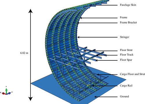
A six-frame section is commonly used in certification drop tests, which are tests performed to quantify the amount of damage with respect to previous tests. Such certifications yield either pass or fail: either the fuselage survives and the acceleration of the passenger ‘dummies’ is survivable, or the fuselage is too greatly damaged or the passenger acceleration is too high. A typical six-frame section implies that the section undergoing the drop test has the approximate average properties in stiffness and mass to represent the overall fuselage. The six-frame model is the same diameter as the full aircraft, and the weight of the passengers (and their baggage) is scaled appropriately. The weights of the engines, empennage, main and nose landing gear and avionics are modelled in the full aircraft, but not with the typical section. shows half of the six-frame model for the A350-like simulations, which is based on a scaled-up version of the A320 model used for validation.
Figure 1. Metal and composite six-frame (half-model shown) for drop test simulation.
Comparative models with metallic components have been discussed in recent publications [Citation11,Citation15–17,Citation21,Citation24]; however, relative to the automotive industry little work on the finite element impact analyses of aircraft is available to the public. The publications mentioned earlier generally use a commercial finite element package, either Abaqus or LS-Dyna, with a damage model for homogeneous metallic materials. Generally, acceptable accuracy was found, in for instance, Liu et al. [Citation16,Citation23], using standard finite element procedures and commercial software.
There are recently advances in modelling with composite materials, as discussed in [Citation10–12,Citation19] in which sections of fuselages are described with varying levels of detail. In particular, [Citation19] gives an outline of optimisation techniques to combine global and detailed finite element methods (GFEM and DFEM, respectively).
Arguments about different modelling techniques can also be found in [Citation7,Citation8,Citation17,Citation19], where various aspects of scaled modelling can be found. This paper details the initial phase work of the finite element modelling for a simplified next-generation typical section model, so a hybrid method is arguably unnecessary, given that the level of detail of the section will anyway limit the accuracy of the final acceleration and deformation result.
Component data for the both the A320- and A350-like models are provided in . The structural composites used in the A350-sized models are called AcF1 and AcF2. The material properties are listed in the next section.
Table 1. Primary structural materials in aircraft models [Citation13,Citation18,Citation20].
As stated in [Citation17], explicit codes are better suited for short-duration, high velocity loading, and although aircraft crashes may have longer duration impacts than other vehicles, the technique is still widely used and considered to be valid over the initial crash impulse. The models in the current paper are built up from a shell representation of a typical section. The model consists of explicit linear quadrilateral, reduced integration elements, with finite membrane strains where appropriate, and second-order accuracy. Elements deformed past damage limitations would be removed from the simulations, which would result in gaps opening in the structure, which may be considered to behave similarly to cracks developing in the physical component. Contact interactions were included within the model definition, which required no active definitions for contact pairs. General contact including self-contact was used for the duration of the simulated impact. Impact with the rigid ground was given a constant coefficient of friction of 0.3 to prevent spurious sliding.
2.1. Material properties
The comparison between the A350-like metal and composite aircraft uses the material data from , but due to proprietary concerns, only the global properties of the composite from classical laminate theory are provided. The metallic components of the model, either Al-2024 or Al-7075, both have isotropic elastic and plastic properties defined. Damage for ductile materials is modelled after the ultimate strength is reached, for which the inherent Abaqus ductile damage model and shear damage models are used. Once an element has undergone a specified amount of strain, the element is removed from the stiffness computation.
Table 2. Primary structural materials in a mid-range civil transport [Citation1,Citation2,Citation13,Citation18,Citation20].
Composite frames are modelled in two ways: the first is quasi-isotropic, so only the composite lay-up as a whole is modelled; and as a laminate, in which the individual plies are included, and the material model reverts to the unidirectional properties of the composite. The quasi-isotropic composite is modelled such that the global properties, as shown in the table, were a priori calculated, using the classical laminate theory. The damage law was input as for a strain-based material: damage occurs after a specified ultimate strain, calculated using the distortional strain energy density, after which there is softening of the constitutional stiffness until failure. Just as with the metallic model, elements are removed when the strain reaches the failure strain.
The ply-by-ply analysis uses the unidirectional properties to calculate the global constitutive properties, but re-evaluates the global properties in an element once some damage has occurred. No plasticity, as defined for the other two models, is modelled. The true plastic strain of the quasi-isotropic model is negligible compared to the true strain, so a damage model is included without plasticity. Damage is calculated using the Hashin criterion for fibre-reinforced composites. For undamaged material, the quasi-isotropic and laminate models behave identically. Once damage has been induced in the ply-by-ply model, the material properties in the damaged elements are degraded until the load-carrying capability of the laminate is reduced to zero; however, the element is removed upon fibre breakage criteria, in tension or compression. Only AcF1 structures are affected by this change in the model; the metal and AcF2 components are modelled identically as in the other simulations.
3. Model validation
Before examining the damages due to impact on metallic and composite fuselage aircraft, some validation of the model is performed relative to the A320 test sections. A six-frame typical section model of an A320 simulates the drop test performed by others [Citation3,Citation8,Citation14]. These tests are not meant to generate precisely the same accelerations and impact pulse, which would be difficult since precise accelerometer data and experimental set-up is often difficult to obtain, but instead to ensure that the accelerations and impact pulse are approximately the same frequencies, magnitude and duration. For that reason, only half of the barrel tests are shown. The accelerations can be compared in Section 3.2, where the full barrel six-frame accelerations are plotted. Additionally, the full model validation will extend from the comparison of an actual crash event.
3.1. A320 drop tests
The A320-sized six-frame model has two accelerometer locations, placed in similar fashion as the A350 model, one is located at the midpoint of the floor spar (Accelerometer 1), and one midway along the first floor track (Accelerometer 2). The first set of figures show the simulation of a drop test, in which a typical section impacts the ground with a speed of 7 m/s. Such a velocity was used by CEAT [Citation5], and it is considered to be representative of a survivable crash scenario. shows the result of the impact on the AircraftFire two-frame model, and shows the experimental impact damage under the same conditions.
Figure 2. Two-frame experiment before and after impact on a rigid ground.
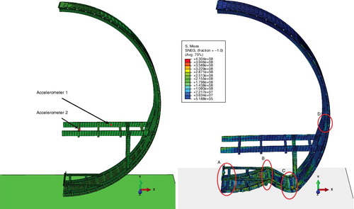
Figure 3. Two-frame experimental collapse test [Citation14].
![Figure 3. Two-frame experimental collapse test [Citation14].](/cms/asset/d852c407-c27a-4f47-b6cf-f23760b9d39a/tcrs_a_1273987_f0003_b.gif)
As one can see from comparing and , the damage is generally consistent. There are three points to focus upon in these figures: the stiffening effect by the cargo floor, the plastic hinges created near the floor strut and the pinch point at the floor within the cabin. First, the cargo bay floor stiffens the structure at the point of contact with the ground. Some buckling is expected along the support strut of the cargo bay floor (encircled by section A in the figure). The stiffness of the support strut of the cargo floor can greatly influence the deformation of the cargo bay zone. If the cargo bay struts are too compliant, the deformation of the cargo bay is extreme, and the cabin displacement is increased. However, if the support structure of the cargo floor is too stiff, then the rivets holding the brackets connecting the frame and the skin shear and are removed from the simulation, and in such a case, the damage to the structures is also increased. In this simulation, the cargo support strut does not buckle sufficiently, which causes additional plasticity at the root of the cargo floor, at section B. Therefore, this does not match with the Hashemi [Citation14] results perfectly; however, adjusting the width of the cargo floor flanges does result in bracket shear and less plasticity.
The second area of interest is just below the floor strut, circled by section C, where plastic yielding can be seen. This plastic hinge is common in the aforementioned drop-test sources. The formation of this plastic hinge seems to play a large role in decreasing the acceleration impulse at the floor level, which will be shown in the comparison of the metal and composite simulations.
During a crash the cabin volume tends to increase, because the floor plunges downward, which causes a moment about the highlighted area D. There is a pinch-point above the floor of the cabin, where there exists a higher stress zone inside the passenger area, which could lead to a plastic hinge. If the material yields here, then the ceiling could become unsupported for additional moments and cause the collapse of the cabin.
3.2. A320 accelerations
shows the acceleration of the preceding two floor locations, after filtering the signal with a Butterworth two-pass 60-Hz filter. The acceleration of the floor track is available from a six-frame drop test [Citation14], and is shown in .
Figure 4. Six-frame model and accelerometer locations on the seat track and floor spar.
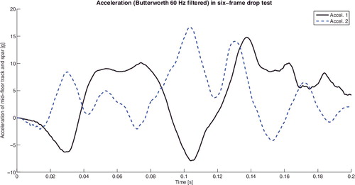
Figure 5. Acceleration from A320 drop test and comparable floor simulation from Hashemi et al. [Citation14].
![Figure 5. Acceleration from A320 drop test and comparable floor simulation from Hashemi et al. [Citation14].](/cms/asset/d25ffa90-2a11-452d-bb72-f4bfd8f3758e/tcrs_a_1273987_f0005_b.gif)
From these two figures, it should be noted that the general trends are accordant, even if the absolute magnitudes are not. Since it was not stated in which locations along the seat-track the accelerometers were placed in the experiment, it is impossible to compare these results directly. However, there is good agreement with the pulses of the acceleration with the Accelerometer 2 data (shown in blue dashes in ) from the simulation in AircraftFire. There seems to be a delay in the acceleration response of the simulation, with respect to the experiment. However, the duration of the acceleration pulses are in better agreement with experiment, even though the acceleration magnitude is halved. This shows that the amount of acceleration for the current simulation is too little, but this does not reflect the amount of damage to the structure. In addition, if one considers the Eiband plot from the DLR [Citation22] research, the acceleration appears to be consistent with various seating locations.
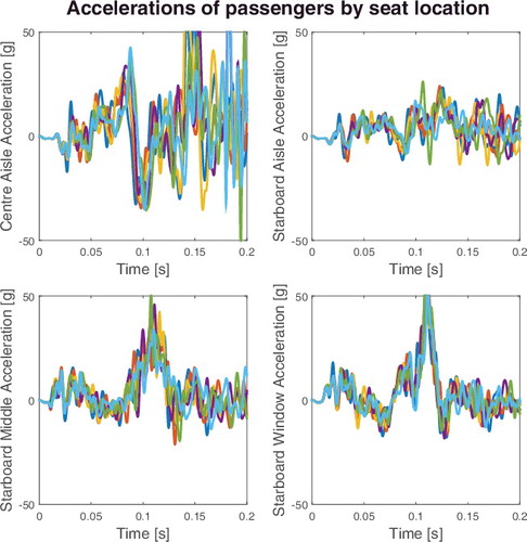
In the six-frame comparison between the metallic and composite variants, only the half-barrel models are used. This is accepted from the resulting comparison of the half- and full-barrel drop test simulations, which showed that until large cracking (element removal) that does not occur in the barrel tests, the accelerations and energy profiles are similar. The accelerations of the port and starboard seat locations, from the analysis of the full-six frame drop test as described, are shown in and . The differences in acceleration for each symmetric seat location are small, but the largest differences are between the middle seat on either side. The largest differences are from the section-cut edges of the fuselage barrel, and in three instances, there is a peak-to-peak disparity of nearly 20 g; however, each lasting for 0.03 s or shorter. Overall, the width and magnitude of the acceleration pulse agrees well.
Figure 6. Portside seat accelerations, 60-Hz Butterworth, low-pass filtered.
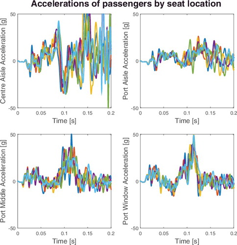
Figure 7. Starboard seat accelerations, 60-Hz Butterworth low-pass filtered.
4. Six-frame drop test material comparison
The A350-like drop tests are simulated in the same manner as the validation drop test with the A320: the velocity of the section upon impact is –7 m/s, and the section is under the influence of gravity as a body load. The accelerometers at the same relative locations as on the A320, one on the floor spar and one on the floor track, measure the acceleration data for the A350-like section drop tests.
shows the level of von Mises stress in the three six-frame sections, at the time of the maximum stress, which occur at different times for each test section: 0.125 s for the metallic section, 0.105 s for the approximated composite section and 0.0825 s for the laminate composite section. Note that the visible deformation is approximately the same, with the exception that the cargo floor for the composite models, shown by A in the figure, have greater bending than the metal cargo floor. This is due to the compliance of the metal frame and the plastic hinge which is forming between the cargo floor and floor strut in the metallic model. The maximum displacement of the floor is consistent between the three models, which implies that the survivable cabin volume is not greatly affected by the difference between these three materials.
Figure 8. Six half-frame von Mises stress level comparison: (a) Metal, (b) quasi-isotropic composite, (c) ply-by-ply composite.
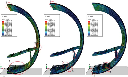
The area encompassed by ‘B’ on the first figure shows that that the cargo floor deforms and has approximate the same stress as the A320 model. The stress on all three models in this area is approximately the same magnitude, however, due to the higher levels of stress in the composites, the shading on the figures is adjusted. Finally, the area within ‘C’ shows the higher stress zone above the floor spar, which is clearly seen in the metallic fuselage structure. It is less obvious in the two composite sections, but a stress concentration is visible in the corresponding area.
It is noteworthy that the maximum stresses between the three models is not consistent. The metal fuselage shows the lowest maximum stress, although this is still past the yield stress of the metals involved. The highest stresses come from the laminate-based model: the maximum stress in that model is 5% higher than that of the quasi-isotropic model and more than twice the maximum stress of the metallic model. Additionally, the highest stresses from all three models, even though they are all in the brackets holding the frames to the skin, appear in different locations between the models: the metallic model shows the highest stresses in both the bottommost brackets (contained within the oval section B) and nearly equivalently in the upper brackets in area D, beside the plane of symmetry. In the quasi-isotropic composite model the lower brackets show significant levels of stress nearest the cargo spar and also at the cabin ceiling as shown by the areas of E. The highest stresses are found in the brackets immediately above the impact site and under the cargo floor, in the laminate analysis shown with the symbols ‘F’. Although the cargo floor has reached its ultimate stress and failed, the yield stresses of the AcF1 and AcF2 materials are much greater.
The floor struts in the two composite models show excessive buckling, and secondary buckling at the locations ‘G’. The flanges in these struts are just on the point of yielding at this time, and examining the same location in , which shows the equivalent plastic strain, indicates that the struts have been permanently deformed. The amount of floor strut plastic damage in the quasi-isotropic model is greater than the other two models, and may indicate why the measured acceleration is correspondingly not as great as those models.
Figure 9. Six-frame (half-barrel) plasticity level comparison: (a) Metal, (b) quasi-isotropic composite, (c) ply-by-ply composite.
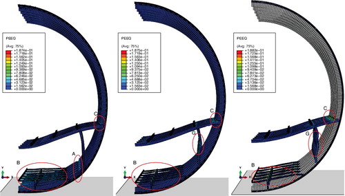
shows the equivalent plastic strain (PEEQ) amongst the models; however, as mentioned in the modelling section, plasticity is not defined for the laminate AcF1 in that model. Therefore, the PEEQ is not defined for the skin, stringers and frame in part (c) of this figure.
In the area labelled ‘A’ there is plasticity in the metallic model between the floor strut and the cargo floor; in the composite models there is no composite plasticity, but referring back to the previous figure, the stresses in the brackets holding the frame and skin together are much higher. This area on part (a) of the figure shows the formation of a plastic hinge, which is expected from the A320 analysis.
The overall plasticity in the cargo area, shown by B, indicates that all three models have comparable plastic deformation. Finally, at C, one can see an interesting phenomenon: there is plastic deformation in the metallic frame model, but not in the floor spar roots. The frames of the two composites do not deform plastically, but there is deformation of the floor spar at the root. There is no significant damage in the corresponding area on the frame of the composite models, which leads one to expect that the failure of the floor spar would occur, as opposed to a failure in the frame. If that occurs, the floor separates from the frame and is unstably supported only by its strut extending to the frame near the cargo bay.
4.1. Energy comparison
shows the kinetic energy, the plastic dissipation and the damage energy for each of the simulations. The metallic section kinetic energy is dissipated more smoothly than the quasi-isotropic composite and the ply-by-ply laminate. In fact, in the quasi-isotropic and laminate, there is a slight increase in kinetic energy during the initial phase of the impact and a corresponding decrease in the rate of plastic dissipation. This effect can be seen more clearly in as the kinetic energy, plasticity and damage dissipation are plotted simultaneously for each simulated section.
Figure 10. Six-frame kinetic, plastic dissipation and damage dissipation energies for each model.
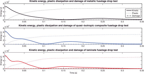
Figure 11. Six-frame energy comparison between composite and metallic sections.
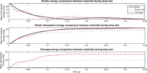
As shown in the materials table, the thicknesses of the skin and brackets are different for the metal and composite sections. With all parts, rivets and passenger and cargo loads modelled, the masses of the three simulated sections is given in . Even though the difference in mass is only 36.4 kg, corresponding to a 1.4% change in mass, the energy comparison is normalised by the mass of each cabin segment.
Table 3. Model masses.
Because there is a greater (absolute) second derivative of the kinetic energy in these plots, one expects to see an overall higher deceleration with the composite fuselages. Also important is the fact that the lowest kinetic energy the fuselage sections achieve occurs at different times. This will be addressed with the acceleration results below.
The plastic dissipation in the metal section is higher than the other sections, although it is interesting that the plastic energy dissipation begins earlier with the composite fuselages. This is likely due to the fact that the rigid composite fuselages impart earlier the contact forces to the cargo and floor structure. Therefore, these structures plastically deform earlier than with the metallic frame, stringers and skin arrangement. Additionally, the laminate fuselage has higher overall plasticity than the quasi-isotropic section. This is curious due to the fact that the damage and ultimate failure of the quasi-isotropic material is modelled based on plastic deformation limits. This can be explained by an increase in plastic deformation in the metallic components, which indicates that the laminate composite damage affects the load distribution to the metallic components. The most likely areas to be affected are the rivets or the brackets near the lowest part of the barrel section.
Damage is initiated very early in the laminate specimen and is 85% greater than the quasi-isotropic section at the end of the simulation. Since the damage begins immediately in the laminated composite, and the slope of the kinetic energy is sharpest for the laminated composite, one expects the acceleration graphs to reflect this result. The metallic specimen damage, by comparison, is negligible on this drop test begins much later. Damage in the lay-up fuselage occurs in the metallic cargo floor, initially. After the initial contact, the inertia of the cargo floor load, the passenger baggage, causes the cargo bay floor to buckle and plastically deform. Due to the rigidity of the frame where it is attached, elements from the cargo floor exceed their ultimate limit, damage, and are removed. This causes the partial collapse of the cargo floor in the laminate fuselage section.
4.2. Acceleration comparison
The time to the lowest amount of kinetic energy in the drop tests are shown in , under the average acceleration time. This represents the time the section took to its lowest kinetic energy point. Since the simulated fuselages all have an initial velocity of 7 m/s, a quick calculation of the average (mean) acceleration shows that the metal section must have an average deceleration as shown by the magnitude in the same table. At these levels, the accelerations do not cause bodily harm, nor yielding stress.
Table 4. Average and measured accelerations.
Unfortunately, not all components of the fuselage are subjected to the same level of acceleration at the same time, nor is the average acceleration representative of the seat track accelerations. shows the acceleration of the aisle seat in the middle of the section for all three material types.
Figure 12. Acceleration comparison using Butterworth filtered signal between three material models.
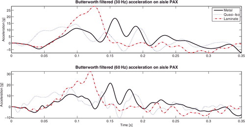
The acceleration analysis shows that the metal section accelerations, as measured at the floor track, has lower acceleration peaks than the laminate composite. Both the metal and laminate composite show accelerations that would cause some moderate injury to a seat occupant. However, the acceleration pulse from the laminate investigation is more severe than the metal simulation floor acceleration. A triangular acceleration curve as is the case for the ply-by-ply composite, means that a 32-g acceleration peak puts that acceleration squarely in the moderate injury category. The maximum peak for the quasi-isotropic composite is within the range for moderate injury, but for most of that acceleration pulse, the acceleration is below what would be considered to cause moderate injury. These accelerations are also on par with the typical accelerations found in civil passenger aircraft [Citation22], but this is better visualised in an Eiband plot. The Eiband plot, which is given in , shows that the amount of acceleration differences of the three simulations in terms of the impact on a human body. It is important to note that the accelerations and damage are approximations to illustrate the potential issues facing designers of composite fuselages.
Figure 13. Six-frame model Eiband plot showing the severity of impact. Redrawn from [Citation6,Citation22].
![Figure 13. Six-frame model Eiband plot showing the severity of impact. Redrawn from [Citation6,Citation22].](/cms/asset/bf6b26a7-4aa0-4b61-a275-58d900496f64/tcrs_a_1273987_f0013_oc.jpg)
As expected from the energy plots, the response of the laminated model is stiffer than the quasi-isotropic model, and as its concomitant, the accelerations experienced at the passenger floor are higher. When modelling the barrel of the fuselage for impact analysis, it is important to know the consequences of choosing to model it as a quasi-isotropic material as opposed to the laminated material. Since the failure strain was one of the element removal criteria for both simulations, and the layers are ‘perfectly’ bonded to one another, the load is non-linearly distributed throughout the element. For instance, an element with its mechanical properties ‘smeared’ (as in the quasi-isotropic case) may be loaded to a point where one or more layers of a laminated element may fail; in this case the smeared properties allow the quasi-isotropic element to maintain its stiffness. However, if the laminated element has failed in some way, the load is distributed differently throughout it. The load transfer results in either a redistribution of load due to layers incapable of carrying load, or a premature failure of the element. In Abaqus Explicit, elements defined with the Hashin damage law are by default only removed when the fibre failure criteria are met (in either compression or tension). As mentioned in Section 3, although there were many damaged elements, there were no elements removed, other than failed rivets, from the drop test simulation.
In detailed analyses, cohesive elements can also dissipate additional energy through the interlaminate contact definitions. While this is more computationally expensive, this can also increase the fidelity of the simulation, and would decrease the accelerations experienced on the seat-track, as some portion of the energy would be dissipated
For quick first-order estimates of the damage in a composite material, it is recommended to use a reduced-model element, such as a quasi-isotropic or quasi-orthotropic element, when applicable. To say that the laminate modelling is inherently more accurate could be misleading; the main difference between the two simulations is the trade-off of computational expenditure for the more detailed ply-by-ply analysis, which can include delamination energy as a source of energy dissipation and the progressive failure analysis of the composite element. An investigation of the assumption that the element should be removed upon fibre failure should be performed. However, full laminate modelling can be more accurate, provided that the delamination energy is properly accounted. Full ply-by-ply modelling is also (for the current simulation nearly eight times) more computationally expensive. Therefore, due to the increase in computational speed, for detailed analyses in which an analyst would want to see the variation of field parameters over the structure, laminate modelling is recommended.
5. Conclusion
The differences between these models show that composite materials, while having an advantage in stiffness, may cause passenger physical injury if the energy of an aircraft crash or impact is not properly dissipated. The energy dissipation of the cabin may instead come from the metallic components, in the floor and cargo structures. The greatest amount of damage is shown in the laminate model and the idealised composite model also shows greater damage than the metallic model. This indicates that the smaller amounts of plasticity available in the composites decreases the kinetic energy dissipation around the whole structure and causes failure in the supporting metallic structure, such as the cargo floor.
The acceleration analysis shows that although the average accelerations are within tolerance of the material and human body, the accelerations measured at floor locations show that there could be minor to moderate bodily damage. The seat track location example shows that the ply-by-ply based section has the greatest acceleration, peaking around 32 g. This is sufficient to cause some injury to passengers aboard the aircraft sitting in such a location. Perhaps surprisingly, the metal test section shows the next highest sustained acceleration peak, which is between 20 and 22 g, depending on the signal filtration. There is a longer sustained acceleration for the quasi-isotropic fuselage; however, the acceleration is only 18 g for a tenth of a second. This is certainly within human survivability limits.
It is expected that the analysis of the six-frame drop test sections will lead to improvement in the understanding of composite impacts and the development of new damage-absorbing materials to dissipate kinetic energy otherwise imparted to the occupants of the aircraft.
Acknowledgements
The authors would like to acknowledge this research was supported and funded by the European Commission Aircraft Fire Project No. FP7-2010-265612-CP-FP. We thank all our colleagues from this project for their insightful criticisms and advice in its completion.
Disclosure statement
No potential conflict of interest was reported by the authors.
Additional information
Funding
References
- AcF1 Manufacturer. Manufacturer [AcF1] Product Data Sheets, March 2010.
- AcF2 Manufacturer. Manufacturer [AcF2] Product Data Sheets, February 2013.
- A. Adams and H.M. Lankarani, A modern aerospace modeling approach for evaluation of aircraft fuselage crashworthiness, Int. J. Crashworthiness 8(4) (2003), pp. 401–413.
- O. Criou, A350 XWB family and technologies, Deutsche Gesellschaft für Luft- und Raumfahrt (DGLR), Hamburg, 2007. Available at http://hamburg.dglr.de/, 2007.
- Centre d’Essais Aeronautiques de Toulouse, A320 fuselage section vertical drop test, part 2: test results, Tech. Rep. S955776/2, IMT Crashworthiness for Commercial Aircraft, CEAT, Toulouse, France, 1995.
- M. Eiband, Human tolerance to rapidly applied accelerations: A summary of the literature, Tech. Rep. Memeo 5-19-59E, National Aeronautics and Space Administration, Lewis Research Center, Cleveland, OH, 1959.
- J. Fabis, B. Langrand, R. Ortiz, E. Deletombe, and D. Delsart, Recent developments in modelling and experimentation fields with respect to crashworthiness and impact on aerospace structures, ECCOMAS 2004, Jyväskylä, 2004.
- E. Fasanella and K. Jackson, Best practices for crash modeling and simulation, Tech. Rep. NASA/TM-2002-211944, National Aeronautics and Space Administration, Army Research Lab, Vehicle Technology Directorate, Hampton, VA, 2002.
- Federal Aviation Administration, Accident and incident data, October, 2011. Available at http://www.faa.gov/data_research/accident_incident/.
- Z. Feng, H. Mou, T. Zou, and J. Ren, Research on effects of composite skin on crashworthiness of composite fuselage section. Int. J. Crashworthiness 18(5) (2013), pp. 459–464.
- J.L.P. Galán, H. Climent, and F.L. Page, Non-linear response of metallic and composite aeronautical fuselage structures under crash loads and comparison with full scale test, ECCOMAS Proceedings, Barcelona, 2000.
- S. Heimbs, M. Hoffmann, M. Waimer, S. Schmeer, and J. Blaurock, Dynamic testing and modelling of composite fuselage frames and fasteners for aircraft crash simulations. Int. J. Crashworthiness 18(4) (2013), pp. 406–422.
- Evonik Industries, Plexiglas gs/plexiglas xt product description, December, 2013. Available at http://www.plexiglas.net/product/plexiglas/en/about/faq/Pages/properties.aspx.
- S.M.R. Hashemi and C. Walton, A systematic approach to aircraft crashworthiness and impact surface material models, Proc. Inst. Mech. Eng. 214(G) (2000), pp. 265–280.
- K.E. Jackson and E.L. Fasanella, Development and validation of a finite element simulation of a vertical drop test of an atr 42 regional transport airplane, Tech. Rep. DOT/FAA/AR-08/19, National Aeronautics and Space Administration Langley Research Center, Hampton, VA, 2008.
- X. Liu, J. Guo, C. Bai, X. Sun, and R. Mou, Drop test and crash simulation of a civil airplane fuselage section. Chinese J. Aeronautics 28(2) (2015), pp. 447–456.
- L.G. Maia and P.H.I.A. De Oliveira, A review of finite element simulation of aircraft crashworthiness, SAE Technical Paper, 2005-01-4012, Brazil SAE Congress and Exhibit., SAE International, Brazil, 2005.
- S. Missori and A. Sili, Mechanical and microstructural properties of 8090 al-li alloy welded joints. Metall. Sci. Technol. 20(2) (2013), pp. 22–26.
- B.A.T. Noordman, W.J. Vankan, and K. Kueres, High and low fidelity finite element modelling in aircraft composite fuselage structural analysis and optimisation, Tech. Rep. NLR-TP-2013-197, National Aerospace Laboratory NLR, Amsterdam, Netherlands, 2013.
- Performance Composites, Mechanical properties of carbon fibre composite materials, December, 2012. Available at http://www.performance-composites.com/carbonfibre/mechanicalproperties_2.asp.
- T.-M. Tan, J. Awerbuch, A.C.W. Lau, and A.D. Byar, Development of computational models for simulating full-scale crash tests of aircraft fuselage and components, Tech. Rep. DOT/FAA/AR-10/34, National Technical Information Services (NTIS), Springfield, Virginia, 2012.
- M. Waimer, D. Kohlgrüber, D. Hachenberg, and H Voggenreiter, The kinematics model – a numerical method for the development of a crashworthy composite fuselage design of transport aircraft, Proceedings of the 6th Triennial International Aircraft Fire and Cabin Safety Research Conference, German Aerospace Center, 2010.
- L. Xiaochuan, S. Xiasheng, G. Jun, and M. Rangke, Crash simulation and drop test of civil airplane fuselage section, Proceedings 2013 International Conference on Mechatronic Sciences, Electric Engineering and Computer (MEC), IEEE, 2013, pp. 3017–3021.
- Z.-F. Yu, H.-S. Gu, H. Wang, and P.-Y. Yi, Crash simulation of the fuselage section with central wing box for a regional jet. Int. J. Crashworthiness 18(1) (2013), pp. 19–28.