
ABSTRACT
In the present study, the effect of resistance spot welding scheme (i.e. single and double pulse welding) on the mechanical behaviour of resistance spot-welded DP1000-GI steel is investigated. It is shown that double pulse welding at low welding current decreases the maximum cross-tension strength and mechanical energy absorption capability of the welds. The factors that lead to the lower mechanical performance of double pulse welds are scrutinised. Local residual stress mapping reveals that the compressive residual stress perpendicular to the plane of the pre-crack either decreases or is fully released at the weld edge of double pulse welds. Orientation imaging microscopy analyses show that the martensite formed in front of the pre-crack of double pulse weld has a lower fraction of high-angle grain boundaries and a coarser structure of Bain groups as opposed to the corresponding area of single pulse weld. Lower mechanical performance of double pulse welds produced at lower welding current is ascribed to the lower compressive residual stress normal to the plane of crack and the formation of martensitic structure in front of the pre-crack with a lower fraction of high-angle grain boundaries and coarser Bain groups.
Introduction
In recent years, the automotive industry has been pursuing vehicle light-weighting approaches in order to reduce carbon emissions with no compromise on safety standards. In this regard, a great deal of focus has been on the use of advanced high-strength steels (AHSS). This class of steels shows a good combination of strength and formability making them an ideal replacement for conventional high-strength steels. Dual-phase (DP) steels with the microstructure consisting of martensite and ferrite belong to the category of AHSSs and are commonly used for safety parts in car bodies, e.g. bumpers and side impact beams, etc., owing to their high-impact toughness [Citation1]. However, increased strength, higher alloying element and new coating technologies have led to challenges regarding the resistance spot welding (RSW) of these steels as the most dominant joining methods in automotive industries. The main issues concerning about the RSW of these steels are failure behaviour and reduction in mechanical strength of spot welds. It has been reported by Tumuluru [Citation2] that there is an increase in the strength of spot weld in the tensile-shear test with an increase in the strength of base materials, whereas the cross-tension properties of many AHSS are inferior compared to those of mild and conventional high-strength steels. Because of ultrafast cooling of the weld during RSW, the fully martensitic microstructure can be easily formed and lead to the brittleness of the joint. Owing to a lower fracture toughness of nugget, the crack can easily propagate through the weld causing brittle fracture during cross-tension test [Citation3,Citation4]. Short-pulsed current was used by Sawanishi et al. [Citation4] in order to enhance the cross-tension strength of AHSS. It was shown that the propagation of the crack was arrested much longer when welding with a pulsed current was applied. The enhancement of the mechanical performance was attributed to a higher fracture toughness of the weld resulting from lower segregation of alloying elements such as P and S. Our previous study showed that the change in the weld scheme from single to double pulse can effectively alter the crystallographic features of martensite that is formed at different welding zone [Citation5]. It was shown that high-angle grain boundaries are a strong barrier against crack propagation, which leads to a higher fracture toughness of the resistance spot weld.
Residual stresses in resistance spot welds play an important role affecting the mechanical performance of the joints. They are self-equilibrating stresses existing in materials in the absence of any external loads or thermal gradients. Accurate and precise measurement of the magnitude, orientation and distribution of residual stresses is of importance to evaluate the durability of welded components. Various studies have been carried out to simulate and measure the state of residual stress in spot-welded joints [Citation6–10]. Lawrence et al. [Citation11] showed that fatigue strength of spot weld improves either by reducing tensile residual stress or inducing compressive residual stress. It was found that preloading treatment could remarkably enhance the fatigue strength by inducing large compressive residual stress at the site of crack initiation at the nugget edge. Anastassiou et al. [Citation12] found that residual stress increased with the thermal cycle intensity and decreased with expulsion or post heat treatment. While X-ray diffraction was used to experimentally measure residual stress at the macroscale, downscaling the resolution of measurement to micron or even sub-micron scales in different weld zones seems to be vital to precisely correlate between the welding scheme and the local residual stress state. Advent of new generation dual-beam field-emission gun-scanning electron microscopes (FEG-SEM) equipped with a focused ion beam (FIB) has enabled precise milling of small volumes of materials. The measure of local stress release due to the milling process can be subsequently quantified by measuring the induced surface displacements by means of digital image correlation (DIC) methods. One of the commonly implemented milling geometries to determine stress gradients is the rectangular slit geometry, wherein stresses are measured along the normal to the plane of slit [Citation13,Citation14].
In this work, the effect of welding scheme, namely single and double pulse welding, on the mechanical performance of resistance spot weld has been investigated. Micro-slit milling method was used to measure the local magnitude of residual stress in the crucial parts of the weld where a crack initiates and propagates under cross-tension test. Besides, the microstructural evolution of weld zones was studied using orientation imaging microscopy (OIM).
Experimental
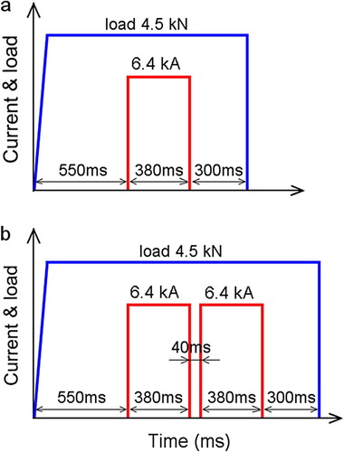
The material examined was DP1000-GI dual-phase AHSS with a thickness of 1.5 mm. Resistance spot welds were produced using a 1000 Hz MFDC pedestal welding machine with constant current regulation and a constant load of 4.5 kN. Welding electrodes (F1 16-20-5.5) and single pulse weld scheme were taken from the VDEh SEP1220-2 welding standard [Citation15]. In order to study the effect of welding scheme on the mechanical and microstructural characteristics of the welds, two welding schemes, namely a single pulse and double pulse welding, were applied. shows the schematic of the welding schemes for single and double pulse processes. The welding current of 6.4 kA was selected based on 4.25√t equation (t is the sheet thickness) to ensure the formation of minimum weld nugget size proposed by standard ANSI/AWS/SAE [Citation16]. For the single pulse welding, 550 ms of squeeze time followed by 380 ms as welding time and 300 ms of holding time was applied. For the alternative double pulse welding, a non-standard procedure was selected. During this welding process, after 40 ms of cooling time, the second pulse was applied with the same duration and current as of the first pulse.
Figure 1. RSW scheme for single pulse weld (a) and double pulse weld (b).
Cross sections of the welds were prepared with conventional metallographic methods and the microstructure was studied via optical microscopy (OM) and SEM. For OIM analyses, the samples were mechanically polished and then electropolished using a solution of 90% CH3COOH + 10% HClO4 at 20 V voltage and 21°C for a period of 25 s. The OIM characterisation was carried out by electron back scatter diffraction pattern using a Philips-FEIESEM-XL30 scanning electron microscope equipped with an FEG operating at 20 kV.
Vickers microhardness measurements were performed at 200 g load for a loading time of 15 s. In order to evaluate the mechanical performance of the welds produced by different welding scheme, cross-tension tests were performed for both single and double pulse welds (150 × 50 mm samples). The properties were evaluated through the average value of four specimens under the same welding condition.
Residual stress measurement started with the decoration of sample surface with yttrium-stabilised zirconia nano-particles to provide sufficiently random, high-contrast features suitable for effective DIC. An area of interest is imaged under the SEM. After capturing the first image, the sample is tilted by 55°, such that the surface is oriented perpendicular to the FIB and milled by Ga+ ion beam. Slits were milled with a width of 0.5, depth of 2.5 and length of 30 µm. Then the sample was tilted back to 0° to capture the identical region after milling. The displacement field perpendicular to the plane of slit was detected via DIC by comparison of SEM images before and after milling. SEM images were captured with a resolution of 768 × 768 pixels under scan integration mode, in order to both optimise the image quality and minimise imaging drifts. DIC was performed using software GOM Correlate 2016. The magnitude of residual stress perpendicular to the plane of slit was measured by empirically fitting the experimentally detected displacements with the displacements calculated from the analytical solution for an infinite length slit in an isotropic linear elastic material [Citation17]:
(1)
where af is the depth of the slit, E′ = E/(1 − ν2), E is the Young's modulus, ν is the Poisson's ratio, θ = arctan (d/a), with d the distance to the slit, and a changing between 0 and af.
Results
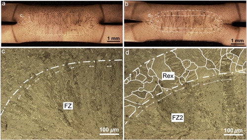
The cross-sectional overview of the weld nuggets is shown in . Single pulse weld shows a typical fusion zone (FZ) microstructure of columnar grains resulting from the rapid solidification process of the RSW ((a,c)). For the double pulse weld, the initial FZ of the first pulse is transformed to two different zones: the inner part composed of columnar grains (named as FZ2), and the outer layer that has an equiaxed microstructure of prior austenite grains (PAGs) (named as Rex-zone), highlighted with white lines in (d). Another difference in the structure is the width of PAGs in the FZ and FZ2 of single and double pulse welds. As indicated by double-edged arrows in (c,d), the coarser structure of PAGs is formed in the FZ2 of double pulse weld.
Figure 2. OM micrograph showing the cross section of single pulse weld (a,c) and double pulse weld (b,d).
Mechanical properties
The nugget size of both welds is ∼5.4 mm, ruling out the possible effect of the weld size on the mechanical behaviour of the welds. Average maximum load and absorbed mechanical energy till the maximum load for two weld schemes are shown in (a). Surprisingly, double pulse welding deteriorates the mechanical performance of the welds. As illustrated, the average maximum load and absorbed energy for the single pulse welds decreases from 7.7 kN and 43.1 J to 6.2 kN and 23.8 J for the double pulse welds, respectively. These results are in contrast to previous reports which showed that double pulse-welded or post-treated samples always show a better mechanical performance [Citation4,Citation5,Citation18–20].
Figure 3. Average maximum load and absorbed energy in cross-tension test (a) and microhardness profile of the single and double pulse welds (b).
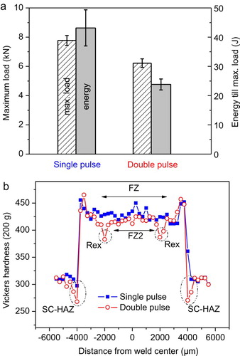
(b) depicts the measured Vickers hardness distribution across the different microstructural zones of the welds. Two major differences between the two welds can be identified. First, there is a significant drop in the hardness of the Rex-zone compared to the FZ2 of double pulse and FZ of single pulse welds. Second, the single pulse weld does not show significant softening at the SC-HAZ, as the hardness of SC-HAZ is almost equal to the hardness of the base metal, whereas the minimum hardness of 269 HV is measured in the SC-HAZ of the double pulse weld versus the hardness (303 HV) of the base metal.
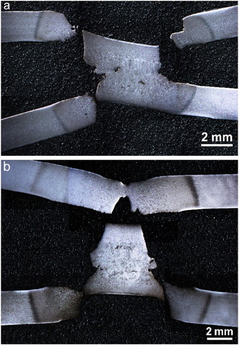
Cross sections of fractured samples after cross-tension test for both welds are shown in . Both samples failed in partial interfacial failure mode as the crack propagated at the faying surface of two sheets into the FZ and then was redirected through the sheet thickness. However, the nugget zone of double pulse weld seems to be more damaged compared to the nugget of single pulse weld. Consequently, the zones in front of the pre-crack including FZ of single pulse welds and Rex-zone of double pulse welds can be considered as the crucial part that determines the crack initiation and propagation rate.
Figure 4. Cross-sectional view of cross-tension tested single pulse weld (a) and double pulse weld (b).
Residual stress measurement
Residual stress is another important factor that can affect the crack initiation and propagation during mode I loading of the cross-tension test. Micrometer-sized slits were made parallel to the direction of the pre-crack at different distances from the weld edge toward FZ and the magnitude of the residual stress in the direction normal to the plane of the slit and/or crack was obtained. (a) shows the SEM image of decorated surface together with the location of slits milled at different distances from pre-crack. The white dot-dashed line indicates the border between the Rex-zone and FZ2 of double pulse weld. Obliviously, all five slits are within the FZ of single pulse weld (not shown), while in the case of double pulse weld, first three slits are located in the Rex-zone.
Figure 5. Milled slits at different distances from the pre-crack (a); surface displacement fields measured by DIC (b), experimental and theoretical displacement curves (c) and fitted curve based on a comparison of experimental and theoretical displacements (d) for slit 1 of single pulse weld.
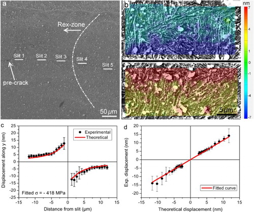
The surface displacement fields measured by DIC after stress release for slit 1 of single pulse weld are shown in (b). As illustrated, displacements of decorating particles are toward the milled slit showing the presence of compressive residual stress. As shown in (c,d), the fitted residual stress value for slit 1 in front of the pre-crack for the single pulse weld is −418 MPa. In order to calculate the fitted σ, the averaging method presented by Mansilla et al. [Citation17] was used through which the displacements along the lines parallel to the slit are averaged prior to fit to Equation (1).
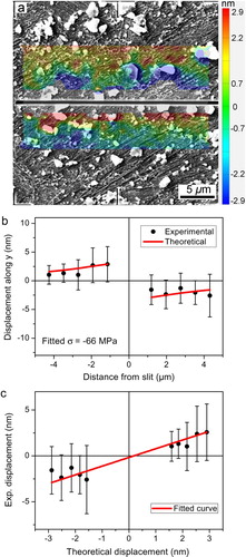
The measured displacement fields and fitted residual stress around slit 1 in front of the pre-crack of the double pulse weld are shown in . It is shown that the residual stress drops to −66 MPa for slit 1 of double pulse weld, which is significantly lower than the measured stress value for the corresponding slit of the single pulse weld. Such a small residual stress was close to the range of resolution of the measurement method and led to unrealistic displacement field in the area far away from the slit, making it impossible to fit the displacement data to the analytical solution. Thus, only the area within the distance of 4 µm from slit was considered in the fitting procedure.
Figure 6. Surface displacement fields measured by DIC (a), experimental and theoretical displacement curves (b) and fitted curve based on a comparison of experimental and theoretical displacement (c) for slit 1 of double pulse weld.
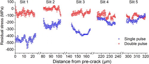
represents the evolution of the measured residual stress from the pre-crack toward the FZ for both single and double pulse welds. As shown, a higher compressive residual stress perpendicular to the plane of the pre-crack was measured in the vicinity of crack tip for single pulse weld. In contrast, in the case of double pulse weld, the compressive residual stress is either very low or almost completely released close to the pre-crack. As shown in (a), slits 1–3 are located in the Rex-zone and their corresponding compressive residual stress is very low compared to the residual stress measured around slits 1–3 of the single pulse weld. Moving into FZ2 (slits 4 and 5), the gradient of residual stress tends to converge with the measured values of the single pulse weld.
Figure 7. Gradient of residual stress from pre-crack toward fusion zone obtained using multiple fitting procedures.
Discussion
There exists a similarity between cross-tension test configuration and standard compact tension sample which is used to measure the fracture toughness under mode I loading condition. Here, the notch at the weld nugget edge acts as the pre-crack that subsequently propagates through the weld nugget under loading. Several investigations have confirmed the enhancement of mechanical performance of the welds using pulsed current. It is believed that the second pulse increases the fracture toughness of weld edge by lowering the segregation of elements such as P and S at the grain boundaries. According to the hardness measurements shown in (b), double pulse welds show more severe softening at the SC-HAZ, which should reduce the stress concentration at the weld edge during loading [Citation21]. Besides, the highly orientated texture of grains evolved from the solidification process in the FZ at the weld edge is changed into the equiaxed structure of PAGs. This can avoid delamination of the structure through the elongated PAGs during crack propagation. This is of great importance when the intergranular fracture occurs through the FZ and elemental segregation is severe. Considering all the mentioned factors, it is expected that the double pulse weld would show a higher mechanical performance compared to the single pulse weld. However, surprisingly, the second pulse of low welding current deteriorates the mechanical properties of the welds in this study.
It was shown that in mode I loading, residual stresses normal to the crack plane affect crack growth rate, whereas those residual stresses parallel to the crack have little effect [Citation22]. High compressive residual stress perpendicular to the plane of the pre-crack can effectively restrain mode I crack tip opening and thus increase the load that is needed for crack initiation and propagation. As the residual stress measurements show, double pulse welding leads to the formation of Rex-zone which has very low compressive residual stress normal to the plane of pre-crack. It seems that the thermal history imposed by the second pulse of low current can release the compressive residual stress in the Rex-zone leading to a lower resistance against crack initiation. It should be noted that RSW is very similar to a thermomechanical process during which the thermal history of weld cycle is accompanied by the mechanical deformation applied by the electrodes. Therefore, the effect of multiple factors such as welding current, welding time, electrode forces and welding scheme on the residual stress must be studied in more details.
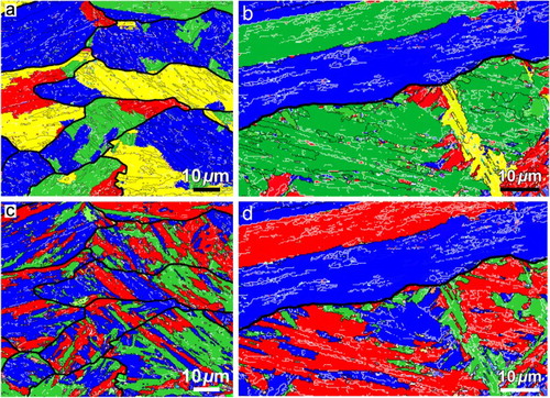
Crystallographic features of the martensitic structure is another factor determining the failure behaviour of the welds and were studied using OIM to get a deeper insight into the microstructure formed in front of the pre-crack. Based on the failure mode shown in , OIM maps were collected from the FZ of single pulse weld and the Rex-zone of double pulse weld in front of the pre-crack, see . Considering K-S orientation relationship (OR) between prior austenite and martensite, variants belonging to different packets and Bain groups of martensite are coloured in different tints. Martensite laths within a packet share the same habit plane of {111}γ, while Bain groups are identified based on compression axes of Bain strain [23]. White and black lines are imposed on the maps indicating the low-angle (5°–15°) and high-angle (>15°) boundaries, respectively. PAGs are shown with bold black lines. Every single packet in the FZ of single pulse weld is subdivided into two or three Bain groups as revealed in (a,c). These Bain groups are separated with high-angle boundaries from each other. In addition, each Bain group contains variants of martensite separated with low-angle boundaries. As observed in (b,d), the Rex-zone of double pulse welds shows a higher density of low-angle grain boundaries. Furthermore, Bain zones are much coarser in this zone compared to the FZ of single pulse weld.
Figure 8. Packets maps of martensite in the FZ of single pulse weld (a) and Rex-zone of double pulse weld (b). (c,d) Bain maps corresponding to (a,b), respectively. White lines are low angle (5°–15°) and black lines are high angle (>15°) boundaries. Prior austenite grains are shown in bold black lines.
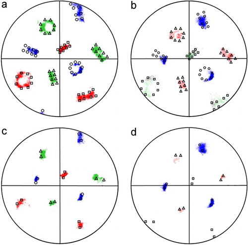
In (a,b), theoretical variants of K–S OR is rotated and superimposed on the {001} pole figure of single PAGs in FZ of single pulse and Rex-zone of double pulse welds, respectively. Three Bain groups are represented by Δ, ○ and □, respectively, in calculated K–S pole figures and by three different colours in experimental ones. As shown, the overall shapes of pole figures exhibit good agreement between the experimental and theoretical results indicating that K–S OR is still applicable in this study in spite of small deviations. In both cases, there are variants that do not appear at the position of theoretical K–S OR, indicating that variant selection occurs for two zones. However, the variant selection is much heavier in the Rex-zone of the double pulse weld as more variants are absent. Clearly, variants of martensite belonging to one Bain group do not appear in the pole figure of Rex-zone. (c,d) illustrates the pole figures of single packets of martensite for two different zones correspondingly. While all three Bain groups are present in the crystallographic packet of martensite in the FZ of single pulse weld ((c)), the packet is dominated by almost one Bain group (coloured in blue) in the Rex-zone of the double pulse weld ((d)).
Figure 9. {001} pole figure of single PAG in FZ of single pulse weld (a) and Rex-zone of double pulse weld (b). Pole figure of a single packet of martensite in FZ of single pulse weld (c) and Rex-zone of double pulse weld (d).
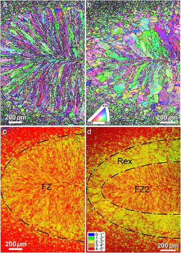
As presented in [Citation5,Citation19,Citation20], the Rex-zone is solidified after the first pulse, whereas the inner part FZ2 remains in the liquid state and is solidified after the second pulse. Once the second pulse is applied, the solid-state Rex-zone undergoes a recrystallisation process that is also associated with rotation and migration of PAGs and rearrangements of dislocation configurations. This process homogenises the matrix and decreases the density of defects. Based on linear elasticity theory, the factors that constrain the martensitic transformation in the Rex-zone are less effective. This culminates in martensitic microstructure with a stronger variant selection in which coarser Bain groups with a high fraction of low-angle grain boundaries are formed [Citation5]. (a,b) shows the inverse pole figure maps of the single and double pulse welds made at welding current of 6.4 kA, respectively. The PAG boundaries are highlighted by black lines using software ARPGE [23]. As shown, the finer and more compact structure of the single pulse weld transforms to a coarser structure of PAGs in the Rex-zone and also FZ2. (c,d) depicts the corresponding kernel average misorientation (KAM) maps of the two welds. KAM shows the average misorientation of a measurement point with its six neighbours and is a qualitative measurement of local strain distribution. Maximum misorientation of 5° was imposed to calculate the KAM maps in the second neighbour configuration. It is shown that the formation of Rex-zone is associated with lower lattice distortion as it has lower KAM value compared to its surrounding zones. Apparently, thermal history of the double pulse weld leads to homogenisation and subsequently partial stress release of the Rex-zone.
Figure 10. Inverse pole figure map and corresponding colour coded kernel average misorientation map of single pulse weld (a,c) and double pulse weld (b,d) made at welding current of 6.4 kA, respectively.
To summarise, the lower mechanical performance of double pulse weld can be explained by two factors: First, the state of residual stress perpendicular to the plane of pre-crack at the weld edge; second, the crystallographic characteristics of martensite formed in the Rex-zone. Lower compressive residual stress normal to the plane of the pre-crack, decrease in the fraction of high-angle grain boundaries and stronger variant selection in the Rex-zone of double pulse weld reduce the resistance of the weld against crack propagation during mode I loading by the cross-tension test. In contrast, there is a higher compressive residual stress in front of the pre-crack of single pulse weld which is composed of blocks of martensite that are highly misorientated and indicate weaker variant selection.
The above-mentioned results clearly confirm how complicated is the mechanical response of resistance spot weld during the cross-tension test. Our previous investigation at a higher welding current of 8 kA showed significantly improved mechanical performance of double pulse welds as opposed to the present study that was performed at lower welding current. The preliminary result of residual stress measurements on the sample welded at high current of 8 kA shows that the compressive residual stress in front of the pre-crack for the single pulse weld, measured at ∼415 MPa, is comparable with that of the single pulse weld made at low welding current of 6.4 kA. However, in the case of double pulse weld made at 8 kA, the compressive residual stress reaches ∼273 MPa, which is higher than the corresponding value for the double pulse weld presented in this investigation (∼66 MPa). The increase in the compressive residual stress for the double pulse weld at high welding current is attributed to the thermomechanical characteristics of RSW. During RSW not only a thermal cycle is applied to the joint but it is also imposed to plastic deformation applied by the electrodes. The weld is subjected to a larger plastic deformation during the double pulse welding compared to the single pulse scheme. It seems that the thermal cycle of the second pulse is able to largely release the residual stresses in the Rex-zone of the double pulse weld at low welding current. However, as the plastic deformation applied by the electrodes increases with the welding current, residual stress is built up in front of the pre-crack with the second pulse of high current. It is also worth noting that double pulse welding at high welding current leads to more intensive SC-HAZ softening that reduces the stress concentration at the weld edge during the cross-tension test. Besides, the larger size of nugget formed at higher welding current becomes the most important parameter that changes the failure mode to pull-out mode during which the crack initiates and propagates outside the nugget. This may also make the residual stress state less effective in enhancing the mechanical performance of the weld. Therefore, multiple factors are involved in determining the mechanical properties of the welds, including weld size, SC-HAZ softening, characteristics of phase transformation and the state of residual stresses at the weld edge. A detailed correlation between welding parameters and all key parameters affecting mechanical properties of resistance spot weld is under investigation for future work.
Conclusion
Mechanical performance, microstructural evolution and the state of residual stress in front of the pre-crack were studied for single and double pulse welded DP1000-GI steel. It was found that double pulse welding at low welding current deteriorates cross-tension strength and energy absorption capability of the weld. Residual stress measurement showed that the compressive residual stress perpendicular to the plane of the pre-crack decreases significantly for the double pulse-welded sample. Furthermore, OIM investigations revealed that the Rex-zone of double pulse weld in front of the pre-crack consists of a low fraction of high-angle grain boundaries and coarser structure of Bain groups. Lower mechanical performance of double pulse welds produced at low welding current was attributed to the formation of Rex-zone in front of the pre-crack with lower compressive residual stress and smaller fraction of high-angle grain boundaries, which leads to lower resistant against crack initiation and propagation.
Acknowledgement
This research was carried out under project number T22.7.13508 in the framework of the Partnership Program of the Materials innovation institute M2i (www.m2i.nl) and the Technology Foundation TTW (www.stw.nl), which is part of the Netherlands Organization for Scientific Research (www.nwo.nl).
Disclosure statement
No potential conflict of interest was reported by the authors.
ORCID
Ellen van der Aa http://orcid.org/0000-0001-5561-1528
Indranil Basu http://orcid.org/0000-0003-2842-9573
Yutao Pei http://orcid.org/0000-0002-1817-2228
References
- Baluch N, Udin ZM, Abdullah CS. Advanced high strength steel in auto industry: an overview. Eng Tech Appl Sci Res. 2004;4:686–689.
- Tumuluru MD. Resistance spot welding of coated high-strength dual-phase steels. Weld J. 2006;85:31–37.
- Dancette S, Fabrègue D, Massardier V, et al. Experimental and modeling investigation of the failure resistance of advanced high strength steels spot welds. Eng Fract Mech. 2011;78:2259–2272. doi: 10.1016/j.engfracmech.2011.04.013
- Sawanishi C, Ogura T, Taniguchi K, et al. Mechanical properties and microstructures of resistance spot welded DP980 steel joints using pulsed current pattern. Sci Tech Weld Join. 2014;19:52–59. doi: 10.1179/1362171813Y.0000000165
- Chabok A, van der Aa E, De Hosson JTM, et al. Mechanical behavior and failure mechanism of resistance spot welded DP1000 dual phase steel. Mater Des. 2017;124:171–182. doi: 10.1016/j.matdes.2017.03.070
- Moshayedi H, Sattari-Far I. Resistance spot welding and the effects of welding time and current on residual stresses. J Mater Process Technol. 2014;214:2545–2552. doi: 10.1016/j.jmatprotec.2014.05.008
- Florea RS, Hubbard CR, Solanki KN, et al. Quantifying residual stresses in resistance spot welding of 6061-T6 aluminum alloy sheets via neutron diffraction measurements. J Mater Process Technol. 2012;212:2358–2370. doi: 10.1016/j.jmatprotec.2012.06.024
- Nodeh IR, Serajzadeh IR, Kokabi AH. Simulation of welding residual stresses in resistance spot welding, FE modeling and X-ray verification. J Mater Process Technol. 2008;205:60–69. doi: 10.1016/j.jmatprotec.2007.11.104
- Cha BW, Na SJ. A study on the relationship between welding conditions and residual stress of resistance spot welded 304-type stainless steels. J Manufac Sys. 2003;22:181–189. doi: 10.1016/S0278-6125(03)90019-7
- Bae D, Sohn I, Hong J. Assessing the effects of residual stresses on the fatigue strength of spot welds – Residual stress at the nugget's edge was taken into consideration in the evaluation of fatigue strength for spot welds of various shapes and dimensions. Weld J. 2003;82:18s–23s.
- Lawrence FV, Wang PC, Corten HT. An empirical method for estimating the fatigue resistance of tensile-shear spot welds. SAE International Congress and Exposition; 1983.
- Anastassiou M, Babbit M, Lebrun JL. Residual stresses and microstructure distribution in spot-welded steel sheets: relation with fatigue behaviour. Mater Sci Eng A. 1990;125:141–156. doi: 10.1016/0921-5093(90)90166-Z
- Sabaté N, Vogel D, Gollhardt A, et al. Measurement of residual stress by slot milling with focused ion-beam equipment. J Micromech Microeng. 2006;16:254–259. doi: 10.1088/0960-1317/16/2/009
- Winiarski B, Langford RM, Tian J, et al. Mapping residual stress distributions at the micron scale in amorphous materials. Metall Mater Trans A. 2010;41:1743–1751. doi: 10.1007/s11661-009-0127-4
- STAHL-EISEN-Prüfblätter des Stahlinstituts VDEh. Testing and documentation guideline for the joinability of steel sheet Part 2: resistance spot welding; 2008.
- ANSI/AWS/SAE standard D8.9-97. Recommended practices for test methods and evaluation the resistance spot welding behavior of automotive sheet steels; 1997.
- Mansilla C, Martínez-Martínez D, Ocelík V, et al. On the determination of local residual stress gradients by the slit milling method. J Mater Sci. 2015;50:3646–3655. doi: 10.1007/s10853-015-8927-y
- Zhong N, Liao X, Wang M, et al. Improvement of microstructures and mechanical properties of resistance spot welded DP600 steel by double pulse technology. Mater Trans. 2011;52:2143–2150. doi: 10.2320/matertrans.M2011135
- Van der Aa EM, Amirthalinham M, Winter J, et al. Improved resistance spot weldability of 3rd generation AHSS for automotive applications. In: Graz, Seggau, Austria, Proceedings 11th International seminar on numerical analysis of weldability; Graz, Austria, 2015.
- Eftekharmilani P, van der Aa E, Hermans MJM, et al. Microstructural characterisation of double pulse resistance spot welded advanced high strength steel. Sci Technol Weld Joining. 2017;22:545–554. doi: 10.1080/13621718.2016.1274848
- Radakovic DJ, Tumuluru M. An evaluation of the cross-tension test of resistance spot welds in high-strength dual-phase steels. Weld J. 2012;91:8–15.
- Lloyd JRT. The effect of residual stress and crack closure on fatigue crack growth. Doctor of Philosophy thesis. In Department of materials engineering. University of Wollongong; 1999.