
Abstract
This article presents a study of fully fixed (welded) perforated beam-to-column connections, used as strengthening techniques to seismic-resistant design. The effect of using non-standard novel web opening configurations of variable depths and positions is investigated. The improvements on the structural behavior foreshadow the enhancements gained using these perforated members. It is concluded that using large isolated perforations is an effective way of improving the behavior of connections enhancing their ductility, rotational capacity and their energy dissipation capacity. Moreover, the connections with novel openings outperform the conventional ones; therefore, they can be suitably used in the aseismic design of steel frames.
1. Introduction
Structural steel frames are widely used in multi-story buildings while their design connections play a vital role. After the 1994 Northridge and 1995 Kobe earthquake, extensive non repairable damage was observed, hence the need for better understanding of connections’ behavior under seismic loading was necessary. Researchers studied various damaged structures following the above earthquakes and concluded that there was only rare evidence of plastic zones which were formed on the beams. The critical components of steel frames which experience yielding, buckling and other inelastic or brittle phenomena during earthquakes, can be identified and subdivided into four main zones: bracings, connections of braced elements, gusset plates and beam-to-column connections [Lehman et al., Citation2008; Nascimbene et al., Citation2011]. In most cases, the seismic energy was absorbed by the connections, and as they were overloaded, they eventually fractured [Miller, Citation1998; Swanson and Leon, Citation2000].
The widespread damage to the welded-steel moment resisting frame systems was one of the major overall lessons of the Northridge earthquake. The overall surprise was the unanticipated brittle fracture in welded steel beam-to-column connections, and hence the behavior of such connections was the first to be investigated under cyclic loading. Consequently, the brittle failures of welded moment connections led to an extensive research campaign conducted by the SAC Steel Project [FEMA 350, Citation2000]. To achieve the basic principle of the well-known capacity seismic design called “weak beam-strong column,” two alternative key concepts were developed. This provides highly ductile response and reliable performance by (a) strengthening the connection, or (b) weakening the beam framed into the connection [FEMA 350, Citation2000; EC8, Citation2005].
The prevalent study performed on the concept of strengthening the connection led to an alternative design of bolted connections. In this case, the extended end-plate moment connections were introduced to replace the welded joints. Studies [Mays, Citation2000; Sumner, Citation2003; Korol et al., Citation1990; Guo et al., Citation2006] indicated that the use of end-plates not only enhances the connections performance under seismic loads but also moves the plastic region from the connection to the beam. Different connection elements and details such as the geometric characteristics of the end-plate, the position of the bolts and their size are critical parameters. However, there are cases where the bolted connections are not suitable, mostly related to their fabrication and maintenance. When a connection has adequate strength and stiffness, it can be assumed as a fully rigid connection, and thus, it is not mandatory to include the connection elements as part of the structural system analysis. Designers usually desire to assume a connection as fully rigid, but due to its structural behavior, it is well known that this is only an idealization. On the other hand, the presence of flexibility in beam-to-column connections may be efficient, but it can increase the inter-story drift and generate dynamic instability of structures. Reinforcing the connection with cover plates, ribs, side plates, post-tensioned connections, haunches, and/or weakening the beam locally at a distance away from the column’s face were therefore introduced as remedies to enhance the connection’s performance [FEMA 350, Citation2000]. Particularly, the idea of weakened beams was developed the last decade, based on the design technique of trimming away steel parts from the region adjacent to the column connection without reducing dramatically the beams’ load bearing capacity. These parts are reduced from the flange resulting to what is known as Reduced Beam Section (RBS) or “Dogbone” connection (). Weakening the beam instead of reinforcing the connections has proved to be more economical, as while reducing the cross-sectional properties, the demand in panel zone and achievement of strong column and weak beam requirements has been minimized.
FIGURE 1 Typical RBS connection and its design parameters.
Experimental and analytical works on RBS connections [Jones et al., Citation2002; Chi and Uang, Citation2002; Pachoumis et al., Citation2009] showed that the yielding was taking place at the reduced region of the beam followed by large plastic rotation without fracture being developed; while no failure occurred at the beam-to-column connection. At large plastic rotations, local buckling was also observed within the plastic region of the flange and the web. Consequently, it was concluded that the RBS can deliver a much higher level of ductility and hence safety as compared to the conventional welded moment connections using solid (plain-webbed) steel beams.
Up until now, researchers have been focused on the strength-, stiffness-, and ductility-based design approach mainly of solid steel beam-to-column connections, while investigating various types of connections and their seismic performance. In parallel, the last decade there is a dramatic increase of use of perforated beams in steel frames as they offer numerous advantages [Yang et al., Citation2009; Lagaros et al., Citation2008; Kazemi and Hosseinzadeh, Citation2011] such as:
the ease to integrate services within the floor-to-ceiling zone and hence maintaining a shallow structural depth;
the reduction of the material volume without reducing the structural strength;
the potential to span longer without being heavier while they comply with the serviceability requirements; and
fewer columns and consequently foundations.
According to the above advances, another effective method in designing aseismic connections is by using the reduction of the beam web cross-section, similarly to the perforated beams, which can be named herein as Reduced Web Section (RWS) connections. Limited research has been conducted on the behavior of connections with isolated web openings to date. Yang et al. [Citation2009] studied the aseismic behavior of a steel moment resisting frame with isolated circular web openings of two different diameters while they were placed at two different positions along the length of the beam. It was established that as the diameter of the opening increased, the yielding load was decreased, while the formation of the Vierendeel mechanism in the weakened area discharged the connection, and hence improved the aseismic behavior of steel moment frames. It was also observed that when the web opening moved closer to column flange, web local buckling and, in some cases fracture, was obtained. Later, Kazemi and Hoseinzadeh [Citation2011] developed a link element to study the behavior of frames with RWS-type connections using Finite Element (FE) analysis. A comparison was established against frames with RBS connections. It is shown that the frame with RWS connections has provided at least the same level of seismic enhancement with that of the frame with RBS connections. Hedayat and Celikag [Citation2009] proposed a different beam end configuration for post-Northridge connections. Through comprehensive FE analyses they proposed two parallel horizontal long voids in the beam web close to the connection which was considered as an effective solution. Moreover, the use of link-to-column connections in eccentrically braced frames having RWS-type connections with various types of perforations was studied by Prinz and Richards [Citation2009]. Their behavior, while investigating various percentages of web reduction, was examined. The outcome was that the presence of circular holes affected the failure mode by reducing the plastic strains in the link flanges and consequently increasing the plastic stresses in the web around the edges of the penetrations. Additionally, it was established that the links with such connections are able to provide either similar or less rotation capacity than the links without the web reduction.
2. Aims and Methodology
This article studies the behavior of RWS connections with isolated web openings as the first step to introduce non standard web opening shapes which have been proven to be efficient solutions for the design of perforated steel beams, while the influence of their geometric characteristics deemed to be drawn. The connections will be imposed under cyclic loading using the FE analysis software ANSYS v12.1 [Citation2009] to gain an in depth view of the stress distribution and their hysteretic behavior. The traditional circular web openings will be replaced with the novel elliptically based web openings proposed and extensively studied in complementary articles [Tsavdaridis and D’Mello, Citation2011a, Citation2012a,b]. The suitability of these new patented perforated beams is now going to be evaluated, for the aseismic design of lightweight steel frames.
In more detail, the effect of the geometric parameters such as the critical length, the depth and the position of the novel openings will be thoroughly examined. It is expected that the outcome will reveal the dominant geometric parameter and it will propose optimum alternative scenarios for the design of RWS connections linked to different applications. A further scope of this study is to identify potential improvements, such as the position of stiffeners in the seismic-resistant design of steel beam-to-column RWS connections.
3. Validation of FE Model
3.1. FE Model
A three-dimensional (3D) FE model was employed using shell elements to model the beam-to-column connection. A fully welded connection was chosen for this study from the literature, since it is prone to brittle failure around the welding area during an earthquake event (i.e., investigating the worst case scenario). The experimental specimen RBS1, as tested by Pachoumis et al. [Citation2009], was modeled to validate the FE model. A nonlinear (geometric and material) analysis was performed and the numerical results obtained were compared with the experimental results. Specimen RBS1 is an exterior beam-to-column connection. illustrates the detailed configuration and the parameters which represent the test set-up.
FIGURE 2 Test set-up (all dimensions in mm).
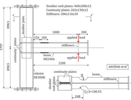
It is worth noting that most of the experimental data found in the literature, unlike the one used for the particular validation herein [Pachoumis et al., Citation2009], based on columns with hinged ends. However, the results can be comparable and in fact the current fixed-end boundary conditions simulate the worst case scenario, while the observations and conclusions regarding the beam-to-column connection behavior remain the same. The assumption of fixed column ends will underestimate the drift of the frame; similarly to the assumption of fully fixed beam-to-column connections as opposed to the more realistic semi-rigid connections. On the other hand, the use of columns with hinged ends can increase the ductility of the frame, and present an advanced ability to dissipate seismic energy through large and full deformation loops; not helpful for the assessment of the connection’s performance.
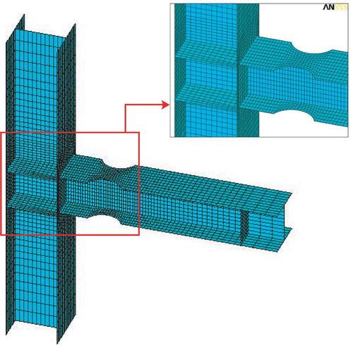
The elaborate FE model is demonstrated in . Since the beam and the column are connected by fillet-welds, these two parts were considered continuous in the FE model, similarly to the literature [Pachoumis et al., Citation2009]. The quadrilateral 4-node shell element (SHELL181 plastic), with six degrees of freedom - 6DOF (i.e., three rotations and three translations) at each node, material plasticity, large deflection, and large strain modeling capabilities, was employed similarly to Tsavdaridis and D’Mello [Citation2011a, Citation2012a,b]. The 4-node shell elements are used due to the fact that they lead to accurate estimations of both displacement and stresses, unlike solid element models, which underestimate the total amount of energy dissipated during the experiments [Uriz et al., Citation2008; Uriz, Citation2005; Santagati et al., Citation2012]. In order to provide accurate results, the meshing is gradually refined towards the beam-to-column interface and the RBS region, as both the welding and the perforated areas are expected to be highly stressed. All 6DOF were restrained at both ends of the column to be in agreement with the experimental test setup where the supports were considered fixed, using extended end plate connections. The free end of the beam was fixed against translation normal to the beam web.
FIGURE 3 3D FE model mesh-work.
3.2. Material
Material nonlinearities were accounted for using a bilinear kinematic rate independent hardening rule, in which the Bauschinger effect is included assuming the total stress range is equal to twice the yield stress. Rice’s kinematic hardening was selected in order to account for stress relaxation. To predict the onset of yielding the Von-Mises yield criterion was activated. Fracture criteria have not included as the focus is on the beam performance while the stresses are moved away from the connection. The material properties for the beam and the column were uniformly selected as: Young’s Modulus E = 207GPa, ultimate stress = 510MPa, and yield stress
= 305MPa. The tangent Modulus was assumed
= 1000MPa based on experimental observations [Tsavdaridis and D’Mello, Citation2011b].
3.3. Loading and Analysis
The specimen was loaded cyclically through beam end displacement in accordance with the SAC loading protocol recommended in FEMA 350 [Citation2000], as is shown in .
FIGURE 4 SAC loading protocol.
To consider the geometric nonlinearity and ensure that the buckling occurs when the model becomes unstable, small geometric imperfections must be introduced before the nonlinear analysis is performed. One way to achieve this is by updating the FE model based on the vectors of an Eigen mode shape reduced by a scaling factor. Therefore, a preliminary Eigen buckling analysis was conducted to obtain the imperfections in the buckling mode shapes. The first mode shape was then used with the recommended [Tsavdaridis and D’Mello, Citation2011b] scaling factor of /200 (7.6/200 = 0.038) to update the geometry of the FE model to the deformed configuration; hence, an imperfect model was generated. Next, the nonlinear analysis was performed and the full Newton–Raphson iterative scheme was used.
3.4. Results
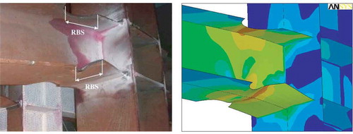
The results of the FE model were compared against the experimental work from Pachoumis et al. [Citation2009]. The local buckling of the beam flange and the yielding of the RBS region shown in the FE model are in agreement with the experimental specimen ().
FIGURE 5 Correlation between FE model and RBS1.
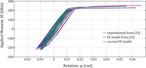
The comparison of the moment-rotation curves between the FE models and the test data from RBS1 recorded at 4cm away from the face of the column (similarly to the specimen in Pachoumis et al., Citation2009) and it is shown in . The rotation was computed by dividing the deflection at this point over the length from this point to the column center line. The maximum applied moment that the experimental specimen experienced is 220 kNm, while the numerical corresponding result of the FE model is 223 kNm, which is only 1.4% different. The comparison of the hysteretic curve and the buckling behavior presents a similar performance. Therefore, considering the number of simplifications and assumptions (e.g., lack of information on material inelastic properties in Pachoumis et al., Citation2009), a good capacity correlation with the experimental work was achieved. It is also worth noting that the thickness of the welding between the beam and the column flanges was not modeled, while special care was only taken to refine the mesh adequately at the critical areas such as at the intersection of the flanges. As the hysteretic curve, plotted in , is very close to the welded region (i.e., only 4 cm away from the column flange), the discrepancy between the current FE model and the results from Pachoumis et al. [Citation2009] is reasonable. Hence, slightly decreased rotation at 4 cm and higher stiffness is observed. Overall, the elaborate FE model was adequately used to perform the parametric nonlinear analyses on the RWS connections subjected to cyclic loading.
FIGURE 6 Moment-rotation curves.
4. Parametric Study
4.1. Novel Reduced Web Section Design
A parametric study was developed to analyze the behavior of novel perforated beams subjected to cyclic loading. For the purpose of this study three opening shapes were considered: one conventional circular opening and two novel web opening ones, which were first introduced by Tsavdaridis and D’Mello following preliminary studies of 11 non standard web opening shapes [Tsavdaridis and D’Mello, Citation2011a, Citation2012a,b]. It was found that perforated beams with elliptical web openings responded better under monotonic static loading when compared to the widely used circular and hexagonal ones. However, the complex geometry of defining an ellipse makes the elliptical shape difficult to manufacture, particularly when the profile cutting procedure is to be used. In order to overcome the manufacturing issue, the idea of a new configuration was developed. The proposed novel web opening configuration is based on a combination of the hexagonal and the circular shapes while they form an elliptically based shape type, as it is presented in . This is formed by two semi-circles at the top and bottom tee-sections connected by four straight lines. To define the shape of these novel web openings three main parameters are introduced: the radius of semi-circles, R, the angle, θ, of the straight lines, and the overall depth, .
FIGURE 7 Novel web opening geometry.
The proposed novel opening configuration is ideal for economic fabrication while the profile cutting and welding processes are simple and easy to provide accuracy during the manufacturing. In the complimentary studies [Tsavdaridis and D’Mello, Citation2011a, Citation2012a,b] it was demonstrated that the novel beams provide efficient structural performance when examined under the most critical failure modes for perforated beams (i.e., Vierendeel mechanism and web-post buckling). The main advantage over the conventional circular openings is that the influence of the opening width is independent of the opening depth, hence deep web openings can be spaced closely along the length of a beam without compromising its load bearing capacity, in contrast to the perforated beams with circular web openings. Thus, the stiffness of the web-post between two adjacent openings is not affected, whereas the weight of the beam is reduced effectively.
These novel web openings are now introduced in the context of beam-to-column connections, however, the current study only focuses on perforated beams with large isolated web openings, mostly being susceptible to high Vierendeel moments, as the first step towards the evaluation of fully perforated beams used in moment connections.
In addition to RWS connections, a beam-to-column connection with a non perforated solid beam was modeled herein as a reference point, to compare and evaluate the structural performance of the new type steel connections.
4.2. Parameters
The parametric study focuses on the effects of the opening depth, , and the distance between the web opening center line and the column’s face, S. The three different configurations investigated are shown in . Also, three different values were chosen for
and S parameters as follows:
is equal to 0.5h, 0.65h, and 0.8h and
FIGURE 8 Geometric parameters
S is equal to 0.87h, 1.30h, and 1.74h,
To distinguish the specimens considered, the configurations were categorized as A, B, and C according to .
Category A: Circular openings with radius r.
Category B: Novel web opening with R = 0.30
Category C: Novel web opening with R = 0.15
Each specimen is represented with a specific three-field identifier, as demonstrated in . For example: C2-300 is the RWS connection with web opening C, of 0.65h, and located at 300 mm away from the column’s face (i.e., S = 0.87h).
FIGURE 9 Specimen classification.
4.3. Mesh Convergence
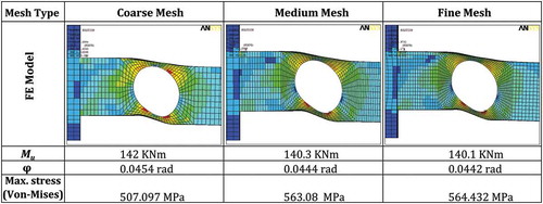
A mesh convergence study was conducted on a typical specimen prior to the actual analysis. Finer mesh was developed in the vicinity of the opening. The mesh was refined until the convergence of the results (i.e., the ultimate moment, stress, and rotation does not significantly vary at further mesh refinement) and the suitable mesh density was eventually defined. A typical mesh convergence study is shown in , in which the medium mesh was considered appropriate for further use.
FIGURE 10 Typical mesh convergence study.
4.4. Analysis
The same cyclic loading as the one used in the validation study was applied to all beams for the consistency of the results. The total displacement of each upward/downward (i.e., half cycle) hysteretic movement of the beams’ free end was applied through a number of sub-steps, starting with an initial displacement which was defined for the first sub-step as a fraction of the total displacement to be applied. The initial applied displacement was taken as the ratio of 1/100 of the total displacement, as this value was found small enough to achieve convergence for the first few cycles. From the cycle 27 onwards, the value of the fraction was decreased to 1/400 to facilitate convergence, due to high nonlinearity of the problem.
5. Parametric FE Results and Discussion
5.1. Hysteretic Behavior
Insightful information about the connection properties can be obtained from the quasi-static hysteretic graphs. The initial rotational stiffness corresponding to the first cycle (), the ultimate moment capacity at cycle 30 (
), the moment capacity at the yielding point (
), the rotational capacity at cycle 30, (
), as well as the rotational capacity at the yielding point (
) of the connection can efficiently capture the connection’s behavior. The hysteretic curves were determined based on the moment capacity at the column center line and the total rotation of the beam at 750 mm away from the face of the column. The rotations were defined from the vertical displacement of the beam divided by the distance to the column center line. The results are synopsized in .
TABLE 1 Summary of results
The comparison of the moment capacities, , revealed that the reference model with solid non perforated beam is the strongest. Undoubtedly, the moment capacity of all the beam-to-column connections using perforated beams is decreased due to the presence of openings. This reduction is significantly affected by the opening depth and the shape of the perforation. The use of the latter connections in steel frames will result decreased rotational stiffness which will further result in decreased initial lateral frame stiffness. This might be of concern if damage limitation requirements (e.g., the design of moment resisting frames according to EC8) for low intensity earthquakes are considered.
When of the same opening shape is increased, the WOA increases, thus the moment capacity of the beam is reduced (, right-hand side). Considering configurations of similar opening depths, the one with the smallest area will obtain the higher moment capacity for the connection. Moreover, larger portion of steel web reduced in beams with circular openings, resulting in decreased moment capacity of the connection. These behaviors can be observed from the hysteretic curves of A1-200, B1-200 and C1-200 in .
FIGURE 11 Hysteretic curves.
It was observed that the rotational stiffness of the connection using circular opening was significantly reduced by 40% when the opening depth, , was increased from 0.5 h to 0.8 h (), while the connections using configurations B and C with similar
, lost 30% and 16% respectively, of their rotational stiffness. Hence, it is concluded that the effect of
on the rotational stiffness of perforated beams with configuration C is not as significant as the other two configurations. The above findings are in agreement with those observed from the monotonic static experiments of perforated steel beams with opening configurations C examined under high vertical shear forces (i.e., Vierendeel mechanism) [Tsavdaridis and D’Mello, Citation2012b] as well as under high buckling loads acting in the web-post between two adjacent openings [Tsavdaridis and D’Mello, Citation2011a].
Further, increased ductility of the connections using beams with circular openings (A) was occurred, as well as decreased moment capacity compared to the connections using beams with openings B and C. Although the position of the opening did not affect the connections’ stiffness significantly, the reduction of the web opening depth resulted in stiffer connections.
Also, it was established that the moment capacity of the perforated beams with large WOA degrades smoothly as the number of rotations increases, followed the yielding. On the other hand, when smaller openings were used, some strength degradation during the final cycles was detected (, right hand side).
The hysteretic behavior of the connections using the “strongest” specimen C1-400, the “weakest” specimen A3-200 and the solid non perforated beam are illustrated in for the ease of comparison. It can be seen that the presence of a large circular opening (A3) with WOA of 6.2 times greater than that of the specimen C1 has reduced by half the connection’s moment capacity, while when the smallest opening located at the furthest position away from the column’s face (i.e., C1-400) did not affect the connection’s behavior compared to the one with the solid non perforated beam. The above results indicate that all (openings’ shape, size, and position) the geometric parameters and their combination play vigorous role in enhancing the performance of the connection under cyclic loading and they should not be treated separately.
FIGURE 12 Moment-rotation curves of solid beam, C1-400 and A3-200 (at 30 cycles).
5.2. Rotational Ductility against WOA
The effect of the WOA on the rotational ductility of the connection was also studied, elucidating the importance of the geometric parameters characterising the opening configurations. As it is shown in , the rotational ductility, Dϕ, was increased together with the WOA. However, the comparison of B1 and C2 at 200 mm and 400 mm away from the column flange (similarly A2 and C3 at 400 mm) in indicates that similar level of ductility can be achieved regardless of the difference in the WOA.
FIGURE 13 Effect of WOA on rotational ductility (Dϕ).
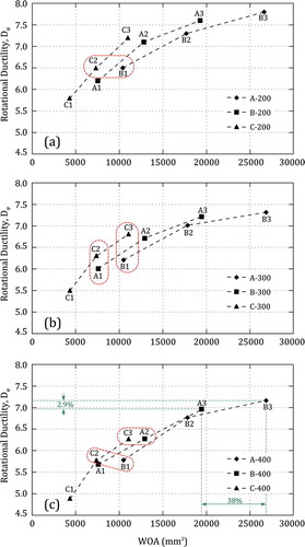
Contrarily, beams with similar WOA can provide different levels of ductility, such as A1 and C2 (similarly B1 and C3) (). Specimen C3, with a deep narrow web opening, is an indicative representation as it is providing higher rotational ductility to the connection, while its Vierendeel moment capacity is also increased in comparison to A3 and B3. Therefore, the use of C3 openings in perforated beams is ideal. As is shown in , the 38% increase in the WOA of A3, compared to the one of B3, increased the rotational ductility by only 2.9%. Therefore, it is concluded that is the dominant controlling parameter for the rotational ductility of a connection together with the web opening shape.
5.3. Vierendeel Mechanism and Ultimate Rotation
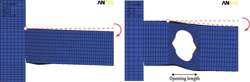
The global shear forces acting on a beam are resisted by the web, hence the local shear stiffness of a perforated beam is decreased significantly due to the loss of a major proportion of the web. The transfer of shear forces along the opening length induces local bending moments, known as Vierendeel moments, in the tee-sections above and below the web opening [Chung et al., Citation2001]. Under the Vierendeel action four plastic hinges are formed in the vicinity of the web opening, as shown in . The plastic hinges are located near the corners of the opening or at particular angles leading to a non uniform large deflection between the low moment side and the high moment side of the web opening, imposing high shearing deformation at the opening area and the flanges.
FIGURE 14 Vierendeel mechanism around the circular web opening and location of plastic hinges.
The Vierendeel deformation is introducing additional rotation to the RWS connection at the position of the opening, unlike to the connections with solid beams, where the rotation is taking place at the face of the column as is illustrated in . This phenomenon signifies the level of strains developed at the column’s face and the opening area. Accordingly, the plastic deformation developed at the opening area promotes the ductility concept of the steel frames as well as moves the plastic deformation away from the column’s face and the welded part of the connection which is susceptible to crack propagation due to fatigue loads.
FIGURE 15 Source of rotation in solid and perforated beams.
It is known that the Vierendeel mechanism is controlled by the critical opening length [Tsavdaridis and D’Mello, Citation2011a, Citation2012a,b; Chung et al., Citation2001; Liu and Chung, Citation2003], meaning that any increase of the opening length will result in increase of the local Vierendeel moments acting at the tee-sections. Perforated beams with circular openings showed a premature formation of plastic hinges compared to beams with the novel web openings, due to their large critical opening length. Specimens of category A1 (i.e., = 0.5h) developed 4 plastic hinges in the vicinity of the opening by the end of the cycle 27 (), while specimens with configurations B and C and of similar opening depth, developed four plastic hinges two cycles later, while providing higher Vierendeel capacity.
FIGURE 16 Von-Mises stress contour plot and Plastic hinge formation; left: at cycle 29, right: at cycle 27.
It is further concluded that in most cases the effect of the distance S is minimal on the ultimate connections’ rotation, (). However, it is worth to mention that the connections with the configuration C are affected by the opening position. The rotation increased as the opening C moved towards the column’s face.
FIGURE 17 Effect of on
.
The loss of local shear resistance and the increase of the Vierendeel moments together with the adverse stress distribution induce significant yielding in the vicinity of the web opening and endure high deformations under cyclic loading. Hence, the connection dissipates more energy through higher inelastic rotation. Consequently, the connection with the perforated beam with circular web opening provided the largest rotation, while the connection with the perforated beam with the novel web opening B showed greater Vierendeel deformation in comparison to the novel web opening C (). It is therefore confirmed that the web opening shape influences differently the Vierendeel bending moment capacity, which is resisted developing local bending moments at the top and bottom tee-sections. On the other hand, the RWS connection with the large novel web opening C is very effective since it eliminates the effect of Vierendeel moments while achieving adequate rotation. Furthermore, it was noticed that using the web openings C, a linear-type performance was acquired when the do/h ratio varies, as opposed to the nonlinear behavior found for openings A and B. This phenomenon makes the use of openings C easy to predict. Moreover, it is worth to note that the lower point in (C1-400) is the proof of concept for , in which the connection with the opening C1 at 400mm away from the column flange reflects the same behavior with the connection with the solid non perforated beam.
Also, it is important to mention that the RWS connections achieved higher inelastic rotation capacity in comparison to the RBS1 connections studied by Pachoumis et al. [Citation2009]. Therefore, certain RWS connections can be considered more effective in dissipating seismic energy.
5.4. Stress and Strain Distribution
The behavior of the connection under cyclic loading is significantly influenced by the stress distribution in the vicinity of the web opening. The top and bottom tee-sections were subjected to a combination of stresses caused by axial and shear forces from the overall beam bending as well as by local moments due to Vierendeel actions. Thus, the failure mechanism of connections should be comprehensively investigated by means of stress and strain distribution.
The flanges of the solid beam close to the connection were yielded first. As the loading was increased the yielded region expanded to the beam web. At later cycles, the stress concentration was increased at the welded area and the plastic strains were developed at the full cross-section of the beam. depicts the Von-Mises stresses, σe, as well as the equivalent plastic strains, , representing the inelastic behavior of the connection. It was observed that the maximum stress was concentrated at the welded area, which could lead to a brittle failure of the connection by weld fracture since the early stages of the cyclic loading. The equations for the Von-Mises stresses and the equivalent strains are shown below:
FIGURE 18 Von-Mises stress (left) and EPEQ (right) contour plots at cycle 31 (loading at 57.5 mm).
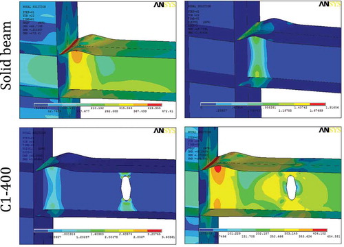
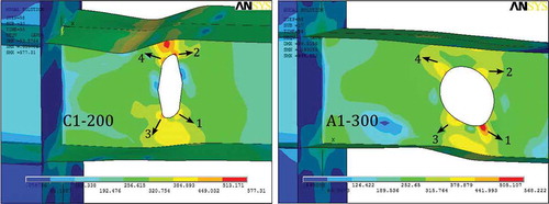
As it was aforementioned, the cyclic behavior of the connection using specimen C1-400 showed that the opening configuration, the opening depth as well as the opening position are crucial parameters to determine the connection’s behavior. Herein, demonstrates the similarity of stress and strain distribution around the welds in both connections. Typical plastic hinges were not formed around the opening and Vierendeel deformation was not observed.
Unlike specimen C1-400, all other connections with perforated beams promote yielding in the vicinity of the web openings, while high stresses were recorded around the area of interest. As stated in FEMA 350 [Citation2000] and also pointed out by other researchers such as Jones et al. [Citation2002] and Kazemi and Hosseinzadeh [Citation2011], the plastic hinge which is formed at the face of the column results in large inelastic strain demands on the weld metal and the surrounding heat-affected zones. These conditions can potentially lead to brittle failure. Therefore, connections with either a solid beam or the specimen C1-400 have somewhat substandard structural performance and they are prone to such failure modes. Contrastingly, examining the connections with perforated beams having large openings located at 300 mm and 400 mm away from the column flange, low stress magnitudes were observed close to the connections.
From the maximum nodal Von-Mises stresses, it was indicated that when the large openings located at 200 mm distance from the column flange, the stress magnitudes at the welded area were increased, while exceeding the material’s yield stress. This designates that both opening depth and opening position parameters are correlated in affecting the magnitude and the concentration of the stresses. As described by FEMA 350 [Citation2000], the fully restrained beam-to-column connections should be configured to force the inelastic action (i.e., plastic hinges formation) away enough from the column’s face, where the performance is less dependent on the material and the workmanship of the welded joint. Based on the latter findings, it was synopsised that the RWS connections with opening depth,, equal to 0.65 h and 0.8 h at distance, S, equal to 300 mm and 400 mm perform ideally.
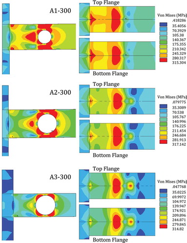
To further illustrate the effect of on the stress distribution, the behavior of specimens A1-300, A2-300, and A4-300 at the cycle 13 is shown in . It was established that when small openings considered, a large area of the beam web and flanges as well as around the welding area were highly stressed. As the opening was increased, high Von-Mises stresses were mainly concentrated in the vicinity of the web opening; consequently the stress concentration around the column flange was eluded. Hence, openings with depth,
, equal to 0.8 h are more successful in distributing stresses locally, around the perforation, allowing plastic deformation to develop only in the controlled opening region, away from the welded area or the beam flanges.
FIGURE 19 Effect of parameter do on stress distribution (loading at 8.6 mm) at cycle 13.
5.5. Local Buckling
As the displacement increased, the specimens experienced local web buckling between the edges of the opening and the column’s face as well as flange local buckling at large plastic rotations. The web local buckling was mainly noticed in small openings ( = 0.5h). Web buckling was not occurred in openings with
equal to 0.8 h, as the Vierendeel mechanism was the dominant failure mode.
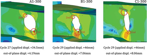
shows that the web of the beams with the novel web openings B1 and C1 was buckled locally at higher applied displacements compared to the beam with circular opening, A1, since they provide higher shear resistance to the perforated beam. The web of the beam with opening A1 buckled severely (at the cycle 29 the out-of-plane web movement is greater than 13 mm), while it is around 7.0 mm and 8.0 mm for openings B1 and C1, respectively. Therefore, it is concluded that circular openings are also more likely to promote local buckling of thin webs which might further affect the stability of the connection.
FIGURE 20 Web local buckling.
Moreover, the initiation of local web buckling resulted in higher strength degradation (). Gradual strength degradation was perceived for beams with large openings. Further, depicts the local web buckling on the edge of A1 opening similarly to the experimental study of Yang et al. [Citation2009].
FIGURE 21 Strength degradation after web local buckling.
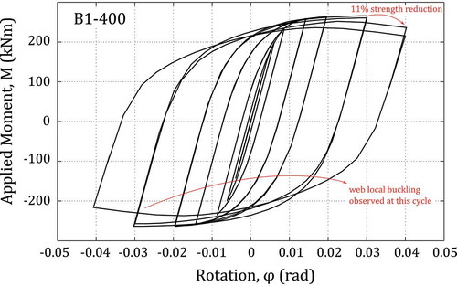
FIGURE 22 Similar failure mode in FEM of this study and experimental work of Yang et al. [Citation2009].
![FIGURE 22 Similar failure mode in FEM of this study and experimental work of Yang et al. [Citation2009].](/cms/asset/85c5ae57-486c-4a1f-ad4e-4d86e8be4fa4/ueqe_a_935834_f0022_oc.jpg)
5.6. Dissipated Energy (E)
The area within the hysteretic curve was computed and presented in to estimate the energy dissipation capacity of the connections. This value is dependent on both the moment capacity and the ultimate rotation of the beam. It was noticed that the dissipated energy was increased for all connections using perforated beams in comparison to the one having the solid non perforated beam (E = 80 (kNm)(rad)). It is also worth noting that despite the major reduction (48-51%) in the moment capacity of specimen A3 due to its high WOA, the energy dissipation was only reduced by 8–12%. This comparison reveals the high plastic rotational capability of the RWS connections, in which the energy dissipation capacity has been effectively improved.
6. Suitability of Novel Beams for Flooring Applications
The desirable behavior under cyclic loading (i.e., sufficient energy dissipation without substantial loss of strength and stiffness), could be achieved with appropriate selection of the opening shape, depth and position. The current study has presented that the use of perforated beams in combination with the novel web openings B and C of the suitable size (i.e., WOA) are excellent replacements for the traditional circular web openings, since they provide adequate moment capacity as well as deliver high rotational ductility and absorb essential amount of energy. At the same time, perforated beams with openings B and C do not experience high stress concentrations [Tsavdaridis and D’Mello, Citation2012a,b] and early stage local web-post buckling [Tsavdaridis and D’Mello, Citation2011a] in the vicinity of the web openings, as they are not sensitive to high shear actions due of their narrow critical opening length at the top tee-section; hence they are not prone to the critical Vierendeel mechanism.
The effect of vertical shear deformation of steel beams using perforated sections with standard web opening shapes (circular, square, elongated, and hexagonal), due to the reinforced concrete slab which rests on top of the compression beam’s flange, has been studied in the literature [Lawson, Citation1987]. The same approach should be used for the current beam configurations, while it is anticipated that the effect of shear deformation due to the slab will be significantly reduced due to the novel shape of the web openings.
The way to control large deformations due to the reinforced concrete slab is by providing enough horizontal shear connection between the steel beam and the metal deck of the slab, hence providing composite construction. This will eliminate excessive deformations in the vicinity of the web openings as well as will prevent the slab from cracking.
A major drawback of the widely used RBS connections, especially if this is used as a retrofit technique in existing structures, is that by reducing the flange size of the section where the floor slab sits, the time and cost of rehabilitation (i.e., cutting the top flange) is increased, while the shear interaction between the steel flange of the beam and the metal deck of the slab might be jeopardized, and thus the degree of shear connection. Consequently, the vertical shear is reduced inevitably. On the other hand, the technique with the so-called RWS connections can be more practical in the above aspects.
Therefore, RWS connections with novel web openings can be acknowledged as more practical when appropriately designed to be used in seismic moment-resisting frames, while they also have other merits compared to the circular openings providing efficient and controllable fabrication at it has been shown in the literature.
7. Concluding Remarks and Limitations
One of the important overall surprises of the Northridge earthquake was the widespread and unanticipated brittle fractures in welded steel beam to column connections. An effective way to move the stressed zone away from a beam-to-column connection is by reducing the cross-section size of the beam. It is well established that the use of flange and web cut-outs located close to the connection can dissipate the seismic energy and effectively control the position of the plastic hinge.
The current study focuses on the use of perforated beams with novel web opening shapes, while they have been manufactured by the cut-out procedure leading to isolated web openings (i.e., widely spaced). The behavior of novel RWS steel beam-to-column connections is examined computationally herein. The geometric characteristics of the beam web opening are examined with scope to alter the stress distribution and alleviate the connection from high stresses. A parametric study is conducted on 28 FE models to examine the effect of the web opening configurations (A, B, and C), the opening depth (), and the opening distance from the column’s face (S), to examine the hysteretic behavior of the connection. It is established that the web openings contributed to the inelastic energy dissipation of the connection by sustaining inelastic rotation.
In more detail, the introduction of a web opening resulted in the reduction of the connection’s moment capacity. The initial rotational stiffness is also reduced. Moreover, the comparison of the WOA and the rotational ductility revealed that openings B and C are more desirable to be used in perforated beams compared to the opening A, especially when is equal to 0.8 h. This can also result in producing lightweight perforated beams with large closely spaced web openings (B and C) with deep webs, without compromising their load carrying capacity.
In addition, from the parametric study it is revealed that all the geometric parameters affected the connection’s behavior in a different way. The variation of the opening depth, , has the highest impact on the connection’s strength and rotational ductility, independent of the distance, S. The distance, S, has slightly affected the connection’s strength and rotational ductility, but it mainly influences the behavior of the connections with configuration C1. It is concluded, that an effective distance from the column’s face can be suggested dependent on the geometry of the opening. It is also comprehended that the connections with a large opening perform better when this is located further away from the column’s face; minimising the stress concentration at the welded region. On the other hand, the behavior of the connections with small openings are somewhat dependent on their actual position, S. In connections with small openings at a distance further away from the column’s face, the effect of the opening is eliminated.
Funding
Dr. Tsavdaridis would like to a knowledge the contribution of the EPSRC DTG CASE support (201324) and TATASTEEL for their generous support.
Acknowledgments
The first author, Dr. Tsavdaridis, would like to thank Miss Faezeh Faghih for the serious work that she conducted during her M.Sc. Thesis at City University, London, in 2012–2013 under his supervision and her effort for the quality control of the FE models/analyses as well as completing this report after the commencement of her Ph.D. studies.
References
- ANSYS [2009] Release 12.1, ANSYS, Inc., Canonsburg, Pennsylvania.
- Chi, B. and Uang, C. M. [2002] “Cyclic response and design recommendations of reduced beam section moment connections with deep columns,” Journal of Structural Engineering 128(4), 464–473.
- Chung, K. F., Liu, T. C. H., and Ko, A. C. H. [2001] “Investigation on Vierendeel mechanism in steel beams with circular web openings,” Journal of Constructional Steel Research 57, 467–490.
- EC8 [2005] Part 3: Design of Structures for Earthquake Resistance. Assessment and Retrofitting of Buildings. EN 1998-3, June.
- FEMA 350 [2000] “Recommended seismic design criteria for new steel moment frame buildings,” Report no. FEMA 350, prepared by SAC Joint Venture for the Federal Emergency Management Agency, Washington, DC.
- Guo, B., Gu, Q., Liu, F. [2006] “Experimental behaviour of stiffened and unstiffened end-plate connections under cyclic loading,” Journal of Structural Engineering, ASCE 132(9), 1352–1357.
- Hedayat, A. A. and Celikag, M. [2009] “Post-Northridge connection with modified beam end configuration to enhance strength and ductility,” Journal of Constructional Steel Research 65, 1413–1430.
- Jones, S. L., Fry, G. T., and Engelhardt, M. D. [2002] “Experimental evaluation of cyclically loaded reduced beam section moment connections,” Journal of Structural Engineering 128(4), 441–451.
- Kazemi, M. and Hosseinzadeh, A. [2011] “Modelling of inelastic mixed hinge and its application in analysis of the frames with reduced beam section,” International Journal of Steel Structures 11(1), 51–63.
- Korol, R. M., Ghobarah, A., Osman, A. [1990] “Extended end-plate connection under cyclic loading: behaviour and design,” Journal of Constructional Steel Research 16, 253–280.
- Lagaros, N. D., Psarras, L. D., Papadrakakis, M., and Panagiotou, G. [2008] “Optimum design of steel structures with web openings,” Engineering Structures 30, 2528–2537.
- Lawson, R. M. [1987] “Design of openings in the webs of composite beams,” SCI, Special Publication 51, joint publication SCI-P068, CIRIA, Berkshire, UK.
- Lehman, D., Roeder, C., Herman, D., Johnson, S., and Kotulka, B. [2008] ”Improved seismic performance of gusset plate connections,” Journal of Structural Engineering 134(6), 890–901.
- Liu, T. C. H. and Chung, K. F. [2003] “Steel beams with large web openings of various shapes and sizes: finite element investigation,” Journal of Constructional Steel Research 59, 1159–1176.
- Mays, T. M. [2000] “Application of the finite element method to the seismic design and analysis of large moment end-plate connection,” Ph.D. dissertation, The Virginia Polytechnic Institute and State University, Blacksburg, Virginia.
- Miller, D. K. [1998] “Lessons learned from the Northridge earthquake,” Engineering Structures 21(4–6), 249–260.
- Nascimbene, R., Rassati, G. A., and Wijesundara, K. K. [2011] “Numerical simulation of gusset-plate connections with rectangular hollow section shape brace under quasi-static cyclic loading,” Journal of Constructional Steel Research 70, 177–189.
- Pachoumis, D. T., Galoussis, E. G., Kalfas, C. N., and Christitsas, A. D. [2009] “Reduced beam section moment connections subjected to cyclic loading: experimental analysis and FEM simulation,” Engineering Structures 31, 216–223.
- Prinz, G. S. and Richards, P. W. [2009] “Eccentrically braced frame links with reduced web sections,” Journal of Constructional Steel Research 65, 1971–1978.
- Santagati, S., Bolognini, D., and Nascimbene, R. [2012] “Strain life analysis at low-cycle fatigue on concentrically braced steel structures with RHS shape braces,” Journal of Earthquake Engineering 16(S1), 107–137.
- Sumner, E. A. [2003] “Unified design of extended end-plate moment connections subjected to cyclic loading,” Ph.D. dissertation, The Virginia Polytechnic Institute and State University, Blacksburg, Virginia.
- Swanson, J. A. and Leon, R. T. [2000] “Bolted steel connections: tests on T-stub components,” Journal of Structural Engineering, ASCE 126(1), 50–56.
- Tsavdaridis, K. D. and D’Mello, C. [2011a] “Web buckling study of the behaviour and strength of perforated steel beams with different novel web opening shapes,” Journal of Constructional Steel Research 67(10), 1605–1620.
- Tsavdaridis, K. D. and D’Mello, C. [2011b] “Finite element investigation on web-post buckling of perforated steel beams with various web opening shapes subjected under different shear-moment interaction.” The 6th European Conference on Steel and Composite Structures (EUROSTEEL), 31 August-2 September 2011, Budapest, Hungary, Vol. C, pp. 1851–1856.
- Tsavdaridis, K. D. and D’Mello, C. [2012a] “Optimisation of novel elliptically-based web opening shapes of perforated steel beams,” The Journal of Constructional Steel Research 76, 39–53.
- Tsavdaridis, K. D. and D’Mello, C. [2012b] “Vierendeel bending study of perforated steel beams with various novel shapes of web openings, through non-linear finite element analyses,” The Journal of Structural Engineering-ASCE 138(10), 1214–1230.
- Uriz, P. [2005] “Towards earthquake resistant design of concentrically braced steel buildings,” Ph.D. thesis, University of California, Berkeley, Berkeley, California
- Uriz, P., Filippou, F. C., and Mahin, S. A. [2008] ‘‘Model for cyclic inelastic buckling for steel braces,” Journal of Structural Engineering ASCE 134(4), 619–628.
- Yang, Q., Li, B., and Yang, N. [2009] “Aseismic behaviours of steel moment resisting frames with opening in beam web,” Journal of Constructional Steel Research 65, 1323–1336.