
 ?Mathematical formulae have been encoded as MathML and are displayed in this HTML version using MathJax in order to improve their display. Uncheck the box to turn MathJax off. This feature requires Javascript. Click on a formula to zoom.
ABSTRACT
This paper evaluates the effectiveness of a novel capacity-design based retrofit for improving both the local and global behaviour of existing reinforced concrete buildings using fibre-reinforced polymers. The approach was previously tested on beam-column joints and is here extended to the building level. A new fibre-element model for the global retrofit is proposed and validated against full-scale experiments. Non-linear push-over analyses confirm the adequacy of the retrofit and fragility analyses are used to compare it to a simpler local retrofit. Finally, cost-benefit analyses for three levels of seismicity highlight the cost-effectiveness of the global retrofit for moderate to high seismicity.
1. Introduction
With the introduction of high-level seismic design guidelines in most European countries in the 1980s (Palermo, Tsionis, and Sousa Citation2018), the seismic performance of modern buildings has been significantly improved. However, structures pre-dating these codes constitute a large proportion of the existing building stock, and still present a high seismic vulnerability (Gkatzogias et al. Citation2022). For instance, 28.9% of all Portuguese buildings are in need of structural strengthening to meet current code provisions (Statistics Portugal Citation2020b). Retrofitting these vulnerable structures not only ensures safety for the occupants, but such interventions extend the lifetime of the structures, resulting in financial benefits (Chiu, Hsiao, and Jean Citation2013; Smyth et al. Citation2004). Very recently, the renovation of existing buildings has been made a priority in EU policies, for instance through the Renovation Wave initiative (European Commission Citation2020) as part of the EU Green Deal (European Commission Citation2019). By combining energy and structural upgrading, even higher cost-effectiveness may be achieved, potentially increasing the uptake of seismic retrofitting measures (Bournas Citation2018; Pohoryles et al. Citation2020).
For what concerns seismic retrofitting of existing reinforced concrete (RC) structures, traditional retrofitting options include RC or steel jacketing, and the addition of RC shear walls. A detailed overview of seismic upgrading techniques for RC buildings was recently presented (Gkournelos, Triantafillou, and Bournas Citation2021). Retrofit schemes involving fibre reinforced polymers (FRP) are being increasingly used as, in comparison to concrete or steel-based retrofitting techniques, they can be performed more rapidly and with less disruption to building occupancy, reducing costs and the need for relocation in residential properties or down-time in commercial spaces (Bousselham Citation2010; Del Vecchio et al. Citation2016). FRP offers benefits over traditional materials due to its high strength-to-weight ratio, low thickness and high resistance to corrosion (Hollaway Citation2010; Triantafillou Citation2001).
Most common applications of FRP retrofit in structures are conducted at the local element/component level. For example, a typical local seismic FRP retrofit in a seismically deficient RC frame aims to improve the element ductility by preventing shear failure or failures associated with a lack of confinement. Interventions include the wrapping of columns for increased confinement, enhanced chord rotation capacity and shear capacity (e.g.: Bournas et al. Citation2007; Bousias, Spathis, and Fardis Citation2007; Ferreira and Barros Citation2006; Sheikh and Li Citation2007), but also strengthening of shear-deficient beam-column joints (e.g.: Alsayed et al. Citation2010; Del Vecchio et al. Citation2014). Detailed design guidelines on the use of FRP materials for local retrofitting of RC structures were provided by Pantazopoulou et al. (Citation2016).
As highlighted by a recent state-of-the-art review (Pohoryles et al. Citation2019), local FRP retrofitting schemes can be considered very well researched and a common-place practice. From the database of experiments compiled in (Pohoryles et al. Citation2019), it can however be concluded that only very limited experimental research on the use of FRP for global retrofitting was carried out (Akguzel, Quintana Gallo, and Pampanin Citation2011; Engindeniz, Kahn, and Zureick Citation2008; Pohoryles et al. Citation2018), i.e. upgrading the internal hierarchy of strengths to promote an improved global behaviour of RC buildings, with an increased global load capacity and ductility of the structure
This paper builds on the recently developed global FRP retrofit scheme for existing RC moment resisting frames (MRF) proposed by Pohoryles et al. (Citation2018). This global retrofitting scheme aims to increase the base shear capacity and displacement ductility of the structure by addressing deficiencies in the hierarchy of strengths between the framing members around beam-column joints. In line with the capacity-design philosophy of Eurocode 8 – Part 1 (CEN Citation2004), through this retrofit scheme, the observed failure mechanism can be changed from brittle joint-dominated or single-storey column-hinging failures to a more ductile beam-sway mechanism.
The global retrofit consists of a combination of various novel elements, including (1) weakening of the slab, (2) flexural strengthening of the column through FRP strands, (3) beam strengthening in shear and flexure and (4) shear strengthening of the beam-column joint with FRP strands. The experiments presented in Pohoryles et al. (Citation2018), tested for the first time the application of the novel FRP strands developed by the authors. Unlike FRP spike anchors, these were not bonded to concrete at the base of the columns, but instead left unbonded and connected through a plastic tube to the lower-storey column. It was demonstrated for full-scale beam-column connections that a much higher load capacity and a more ductile beam-sway mechanism can be achieved, with damage being concentrated in a designed-for plastic hinge location in the beams and away from the joint panel and columns, hence safeguarding the vertical load resisting mechanism.
As the proposed global retrofit scheme is more invasive and complex than a typical local retrofitting intervention, it is crucial to understand how the observed behaviour at the beam-column joint sub-assembly level would translate to the building level. The present paper aims to evaluate if and when such a global FRP retrofitting scheme is more beneficial than its local retrofitting counterpart. In order to carry out such evaluation, a cost-benefit analysis in line with the PEER performance-based earthquake engineering (PBEE) methodology (Porter Citation2003) is presented. To do so, fragility curves of a retrofitted building are required. There is however a lack of fragility curves explicitly taking into account the retrofitting application, particularly for FRP (Yurdakul et al. Citation2023). Most studies instead assume either fragility curves of buildings designed to modern seismic codes (e.g.: Kappos and Dimitrakopoulos Citation2008; Pohoryles et al. Citation2020) or modify the parameters of fragility curves through the results of push-over analyses or experiments (e.g.: Cardone, Gesualdi, and Perrone Citation2019; Mastroberti et al. Citation2018). Here, instead, the first analytical fragility curves for a globally retrofitted RC building are developed based on non-linear dynamic time-history analyses.
Given the particularity of the global retrofitting scheme, employing FRP strands for the flexural retrofitting, and selective weakening of the slabs, a new modelling approach is necessary, as there is currently no “off the shelf” model for the FRP strands. This model is presented here for the first time and is validated against previous experimental results for beam-column joints (Pohoryles et al. Citation2018) and then extended to a Portuguese mid-rise RC reference building designed to a pre-1980’s design standard. To evaluate the potential benefits of the proposed global retrofit design approach, it is compared to a typical local FRP retrofit scheme applied to the building columns. First, an assessment according to Eurocode 8 – Part 3 (CEN Citation2006) is performed by means of a push-over analysis to confirm the adequacy of the proposed retrofits. Then the two retrofit schemes are assessed through non-linear dynamic time history analyses using 20 earthquake records and fragility functions are developed. To this end, a new empirical damage scale for FRP retrofitted structures is proposed, whereas the newly developed fragility functions are then used to conduct a cost-benefit analysis based on expected annual losses from seismic events for three different levels of seismic hazard in Portugal. Finally, the long-term impacts and investment pay-back times for the local and global retrofit are discussed.
2. Methodology
To assess the effectiveness of the proposed global FRP retrofit scheme in a more general context, the retrofit design approach is implemented to a seismically deficient case study reference building and compared with a local retrofitting scheme. For this purpose, a new fibre-element modelling approach for the global retrofit is proposed and validated, before applying the retrofit to the case study building modelled in SeismoStruct (Seismosoft Ltd Citation2018). A set of incremental dynamic analyses (IDA) was then carried out to assess the fragility of the building and the cost-benefits of the two retrofits. The procedure is described in this section, where the reference building is first presented, then the numerical model and definition of damage states are presented to finally describe the analysis of the building.
2.1. Reference Building
The reference building shown in is a mid-rise (four storey) RC building designed to the Portuguese RC building code of 1967 (REBA Citation1967) to resist a lateral load (base shear) of 0.05 of the building weight (seismic zone C). The storey height is 3.0 m throughout the building and it has three bays in the weak x-direction and five bays in the y-direction, with a bay-width of 4.0 m in both directions. The total floor area of the case study four-storey building with three by five bays is 960 m2. It is assumed that 70% of this is total floor area is useful floor space (672 m2).
Figure 1. Reference mid-rise building designed to the Portuguese REBA (Citation1967) guidelines (in m).
The detailing shown in leads to a number of seismic deficiencies typical of pre-1970’s RC residential buildings in Southern Europe. These deficiencies lead to brittle failure mechanisms due to an inappropriate hierarchy of strengths, with a lower flexural capacity of the columns than the beams (weak-column/strong-beam mechanism) and a low shear capacity of the joint (due to the absence of shear reinforcement in the joint), as well as a lack of confinement in the columns with inadequate transverse reinforcement spacing.
From the reference four-storey structure, full-scale beam-column joint specimens in the as-built (control) and retrofitted configurations were tested experimentally under cyclic loading. The specimens were interior beam-column joints, consisting of two half-storey 1.50-m superior and inferior columns, as well as two half-span main beams (2.05 m) and two stub transverse beams (825 mm long) with the cross-sectional dimensions shown in . Additionally, the specimens presented a 1.95-m-wide slab, with a depth of 150 mm. The concrete used for the construction of the experimental specimens had a characteristic cylinder strength of 25 MPa, while the Φ12 and Φ8 steel reinforcement bars had a yield strength of 450 and 540 MPa, respectively. Further details of the experiments and the specimens can be found in (Melo et al. Citation2021; Pohoryles Citation2017; Pohoryles et al. Citation2018).
2.2. FRP Retrofit Design
The aim of this study is to compare the global FRP retrofit design proposed in (Pohoryles et al. Citation2018) with a typical local FRP retrofit, consisting of FRP wrapping of the columns and strengthening of the joints. For the sake of consistency, the local and global retrofits are both designed to comply with the displacement-based assessment according to Eurocode 8 – Part 3, EC8–3 (CEN Citation2006), for the same level of seismic hazard. For the purpose of the assessment, the target displacements are first calculated for a peak ground acceleration (pga) of 0.25 g (e.g. 10% of exceedance in 50 years for Lisbon in Portugal) for soil type B, as shown in .
Table 1. Eurocode 8 target displacements in m (and roof drifts in %) for the three buildings for a reference pga of 0.25 g.
By means of the non-linear push-over analyses presented here-in, compliance of the building for the code-obtained target displacements (cl. 4.3.3.4.2.6(1) Eurocode 8 – Part 1) is checked using the safety verifications for the limit states of Damage Limitation (for an event with 20% probability of exceedance in 50 years), Significant Damage (10% in 50 years) and Near Collapse (2% in 50 years). The demand on the structure at the target displacement is defined in terms of the chord rotation θE and shear forces VE in the RC members as shown in , with the retrofits being designed such that the chord rotation and shear strength capacities are not exceeded in the elements at the respective target displacements. Instead, the control building, which is designed to a low level of seismic design code, should not comply with the assessment.
Table 2. Compliance criteria for the assessment of RC structures and retrofitted members in Eurocode 8.
Where θy is the chord rotation at yield, evaluated using equations A.10.a and A.11.a of Eurocode 8 – Part 3, and θum ultimate chord rotation capacity of RC members under cyclic loading, which is calculated from equations A.1 and A.3 of Eurocode 8 – Part 3. For FRP-wrapped members, the ultimate chord rotation capacity equations are adapted to consider confinement according to equation A.35 of Eurocode 8 – Part 3. Finally, VRd refers to the shear capacity of RC members, checked according to equation A.12 for the non-retrofitted members and A.33 for the FRP-wrapped members in the retrofitted buildings.
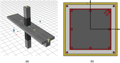
For the sake of comparability, in both, the local and global retrofits, the equations for FRP-retrofitted RC elements of the Italian CNR DR 200.R1/2013 guidelines (CNR Citation2013) are used to calculate the required number of FRP confinement layers in the columns, to verify the provided shear strength enhancement in the columns, as well as to check adequate shear resistance to the joints. The CNR design equations are selected as their adequacy was previously tested on a large database of experiments (Pohoryles et al. Citation2019). In both retrofit schemes three layers of 250-mm-wide FRP confinement wraps are provided at the column ends, and two layers are extended for the rest of the column length, while two 150-mm-wide FRP strips spaced at 100 mm were used to improve the joint shear capacity (see ). The Carbon FRP sheets used for the retrofit have a nominal thickness of 0.223 mm, an elastic modulus Ef of 194.1 GPa and an ultimate strain εu of 1.7%.
Figure 2. (a) Retrofit of column and joint in both retrofit schemes; (b) additional retrofitting applied in the global retrofit scheme.
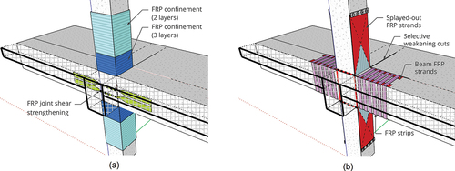
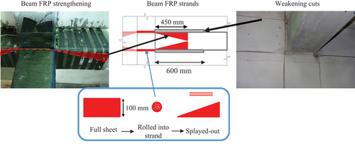
Additionally, the proposed global retrofit prescribes a number of interventions to ensure a strong-column/weak-beam hierarchy of strengths. The additional retrofit interventions are shown in (b). It foresees the flexural strengthening of the columns with 2-m-long FRP strands, made from six layers of 500-mm-wide FRP sheet rolled together and then splayed-out over a length of 750 mm and bonded to the upper and lower columns and anchored using steel anchors. The FRP strands remain unbonded and are inserted in a plastic tube () over the length of the joint panel (500 mm). Moreover, the beams are strengthened in flexure near the beam-column joint, using two 100-mm-wide FRP strips rolled into FRP strands. These were attached to the beams over a length of 450 mm (one beam depth) on either side of the joint (). Through the combination with selective weakening cuts of the slab along the beam sections for a length of 600 mm (2 column depths), a targeted plastic hinge relocation away from the joint can be achieved. To resist the additional shear forces in the beams and anchor the beam FRP strands, 50-mm-wide FRP strips are applied as full wraps through the weakening cuts with a spacing of 75 mm. Further information on detailing and retrofit design can be found in (Pohoryles et al. Citation2018).
Figure 3. Detailing of the vertical FRP strands for flexural strengthening of the columns.
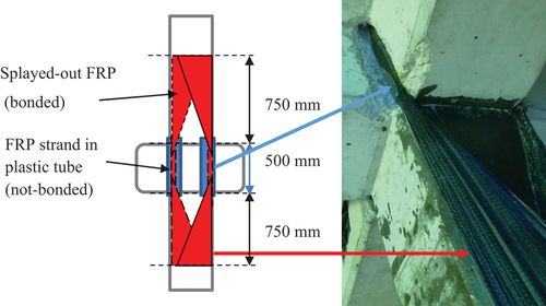
Figure 4. Details of beam FRP strengthening and selective weakening cuts.
Clearly, the proposed global retrofit design is more expensive and more demanding in terms of design and application than a local retrofit. However, it is more effective in reducing damage and risk of collapse, as was previously demonstrated experimentally (Pohoryles et al. Citation2018), potentially facilitating repair and promoting a more rapid restoration of building functionality after an earthquake. Hence, a cost-benefit analysis of the two retrofit strategies is presented in Section 0 to investigate at which point the benefits of the more demanding global retrofitting scheme exceed those of the simpler and cheaper local retrofit scheme.
2.3. Numerical Model
2.3.1. Modelling Parameters
Based on the experimental specimens from Pohoryles et al. (Citation2018) for the control (C1) and globally retrofitted (C1-RT-B-sw) beam-column joints, a simplified fibre-element model is developed in SeismoStruct (Seismosoft Ltd Citation2018) for validation purposes. The rectangular RC sections for the beams and columns are modelled as lumped plasticity model using inelastic force-based fibre elements with plastic hinge lengths of 16.7% of the element. Each column cross-section was discretized into 150 section fibres, while the beams into 100 fibres. The behaviour of the sections is obtained through integration of the stress-strain response of the individual fibres, which are each associated with uniaxial stress-strain relationships for the relative materials, as described in the following paragraphs.
For the concrete material, a nonlinear model with the stress – strain relationship for confined concrete developed by Mander, Priestley, and Park (Citation1988) is used, with the lateral confinement effect from transverse reinforcement incorporated assuming constant confining pressure throughout the full stress – strain range. Under uniaxial compression, the concrete strain at peak stress was assumed to be 0.002 and the tensile stress capacity was simplified to 0. Moreover, the Poisson’s ratio (νc) for concrete under uniaxial compressive stress of 0.2 was considered. Based on the material used in the experimental study (Pohoryles et al. Citation2018), the concrete was modelled with a mean compressive strength fc = 25 MPa and a modulus of elasticity of concrete Ec = 23.5 GPa, while its specific weight is considered as 24.0 kN/m3.
The steel material is modelled through a uniaxial bilinear stress – strain relationship with kinematic strain hardening, according to Menegotto and Pinto (Citation1973), coupled with the isotropic hardening rules proposed by Filippou and Fenves (Citation2004). According to the material properties in the experimental study, a yield strength fy = 450 MPa is used for the steel reinforcement, with an elastic modulus of 200.0 GPa and a specific weight considered as 78.0 kN/m3. For the FRP retrofitting of the columns (for both local and global retrofitting schemes), the FRP jackets are modelled using the FRP wrapping model in SeismoStruct, which increases the shear capacity and confinement of the column and joint sections according to the aforementioned equations in Annex A Eurocode 8 – Part 3 (CEN Citation2006). The material properties for the FRP are modelled using a uniaxial elastic stress-strain relationship, up to an ultimate strain of 1.7% with properties according to the materials used in the experimental study, with an elastic modulus Ef = 194.1 GPa and a thickness of 0.223 mm.
Additionally, for the globally retrofitted specimen, shown in , flexural FRP strengthening is applied to columns and beams in form of FRP strands, and their effects on flexural strength must also be modelled. However, as this is not a standard retrofit procedure, no model is available for modelling the FRP strands. The geometry of the retrofitted columns is hence modelled using the “jacketed RC section,” where the FRP strands are represented as four external reinforcement bars embedded into the concrete cover at the corners as shown for the column in . The material of the reinforcement bars is however not defined as steel, but instead uses the cyclic uniaxial linear elastic FRP material model. It is noted that in the real retrofit, the FRP strands are not bonded along the length of the joint, which leads to a lower strain in the FRP strands than that which is modelled (Pohoryles et al. Citation2018). To account for this, an equation for reduced FRP strain was developed by calibration to the experimentally measured strain in the FRP strands (Pohoryles Citation2017) and is applied here by reducing the elastic modulus for the FRP bars to 75 GPa (i.e. 38% of the actual value). Finally, in the global retrofit, to represent the effect of the selective beam weakening, the effective width of the RC slab in the beam T-sections is also reduced by the length of the slab selective weakening cuts (600 mm).
Figure 5. (a) Model of the retrofitted joint; (b) section detail for FRP retrofitted RC columns.
2.3.2. Validation of Numerical Model with Experimental Results
The experimental results of Pohoryles et al. (Citation2018) are used as validation of the numerical models. In the experiments, the behaviour of the control specimen (C1) is dominated by a single storey failure mechanism, with heavy damage to the column ends and bar buckling. For the globally retrofitted specimen (C1-RT-B-sw), instead, a much more ductile and dissipative behaviour is observed, with yielding recorded in the expected PH location in the beams and cracking spread-out along the length of the beam.
The overall hysteretic behaviour of the specimens is shown in with the damage states also indicated. Specimen with the C1–RT-B-sw achieved a significantly higher lateral load capacity (+39%), as well as displacement ductility (+89.6%), compared to the seismically deficient control specimen C1. As shown in , using the material properties and geometry of the experimental specimen, the hysteresis of the as-built beam-column joint specimen is adequately represented by the model. The peak force of 61.9 kN matches the experimental results very well (−1.86%), but also the general behaviour is well reproduced with a similar initial stiffness and post-peak softening as the experiment.
Figure 6. Hysteresis curves of the experimental and modelled beam-column joints for the control (C1) and global FRP retrofit (C1-RT-B-sw) specimens.

For the global retrofit specimen, to achieve a hysteresis curve close to the experiment as shown in , the reduced strain experimentally observed in the FRP strands had to be modelled. To do so, the effective FRP elastic modulus was reduced to 75 GPa (i.e. 38% of the actual value) for the FRP strands. This is in line with the experimental measurements of FRP strain, which were less than half of the strain predicted using the guideline equations (Pohoryles Citation2017). With the calibrated elastic modulus, a peak force of 88.9 kN, corresponding to a value slightly above the experimental value is obtained (+2.35%). While the model hence adequately represents the experimentally recorded peak loads and displacement capacities, it has to be noted that the simplified fibre model is not able to perfectly capture the energy dissipation, which was characterised by more significant pinching in the experiment and then in the model. This overestimation of dissipated energy in the model will, in turn, lead to a certain degree of overestimation of the cost-benefit of retrofitting. It is however not the main aspect in defining the latter, as the increase in ductility of the retrofitted specimen, which is adequately captured by the model, is also associated to a decrease in damage state at higher levels of drifts, as described in the next section.
2.3.3. Building Analyses
The three fibre-element models of the reference RC building and its retrofitted counterparts are used to conduct a series of adaptive push-over analyses and IDAs (Vamvatsikos and Cornell Citation2002). Due to symmetry, only two frames of the building in the weak direction are modelled to reduce computation. The total applied gravity loading considered is 12kN/m2.
To analyse the response and failure mechanism of each building model, and to verify the compliance of the retrofit designs with the displacement-based assessment described before, a static adaptive push-over analysis (Antoniou and Pinho Citation2004) is first carried out for the three cases in 800 steps up to a roof drift corresponding to the target displacements defined in or to structural or numerical collapse (20% reduction in peak strength). In the adaptive pushover procedure, the displacement-based lateral load patterns are continuously updated at each step of the analysis according to the changing modal properties of the system. This is applied in SeismoStruct (Seismosoft Ltd Citation2018) through the algorithm developed by (Antoniou and Pinho Citation2004), where the applied displacement at each storey is based on the modal characteristics and the spectral shape of the structure. The latter are evaluated and updated through an eigenvalue analysis at each step of the pushover in order to be able to capture irregular response features (e.g. soft storey).
For the IDAs, a set of 20 natural earthquake records from Europe, summarised in , are chosen using the REXEL record selection tool (Iervolino, Galasso, and Cosenza Citation2010) to match the Eurocode 8 spectrum for ground type B. shows the individual record spectra, as well as their mean spectrum together with the Eurocode 8 target spectrum (soil type B). The upper and lower bound structural period limits for the spectral matching were chosen in accordance with Eurocode 8 – Part 1 (CEN Citation2004) to be 0.2•T1 and 2•T1, where T1 = 0.56 s is the average natural period of the three structures obtained from an eigenvalue analysis (ranging from 0.58 s for the control structure to 0.55 s for the global retrofit). The criteria for the record selection were set with a lower bound tolerance of 10% and an upper bound tolerance of 30% for the resulting mean elastic spectrum from records with regard to the code design spectrum. The 20 records were then scaled for values of pga from 0.05 g to a maximum of 1.0 g for the IDAs.
Figure 7. Target and mean spectra for the 20 selected ground motion records, normalised by pga.
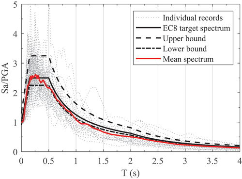
Table 3. List of selected 20 earthquake records for the incremental dynamic analysis.
The construction of the fragility curves for different damage states (DSi) is based on the common assumption of a lognormal cumulative distribution function (D’Ayala et al. Citation2014). Two conventional intensity measures, namely the peak ground acceleration (pga) and the spectral acceleration at the natural period of vibration for 5% damping of the as-built structure, Sa(T1), are selected to create the fragility curves. Using the method of maximum likelihood fitting (Baker Citation2015), the median value (θi) of the intensity measure at which the building reaches the inter-storey drift threshold of damage state DSi (see ) and the standard deviation (βi) of the natural logarithm of the intensity measure for damage state DSi are derived. The fragility function parameters (mean and standard deviation) are obtained by varying the parameters until the likelihood function is maximized using the code developed by Baker (Citation2015).
Table 4. Inter-storey drift values for the four damage states.
The four damage states used here are based on the damage state descriptions of the harmonized reinforced concrete (HRC) damage index (Rossetto and Elnashai Citation2003). Light damage is defined as the onset of cracking, moderate damage corresponds to the first record of yielding in the reinforcement, and extensive damage is defined as the attainment of the peak lateral load. Finally, collapse or near collapse is defined as a 20% drop in peak capacity. The inter-storey drift limits corresponding to each damage state are structure-specific, and are based on experimental observations made in Pohoryles (Citation2017) on full-scale beam-column connection specimens for the same structure design. These inter-storey drift limits are summarised in .
To associate the respective damage states to monetary losses, the loss function in Silva et al. (Citation2015) for the development of vulnerability functions for the Portuguese RC building stock is adopted in this study (see ). These loss functions are compatible with the damage state definitions used here as they are also defined based on Rossetto and Elnashai (Citation2003). It is noted that these loss functions allow only the direct losses related to repair or demolition of the building to be evaluated.
Table 5. Damage-to-loss function for Portuguese RC buildings according to Silva et al. (Citation2015).
2.3.4. Cost-Benefit Analyses
Finally, to compare the two retrofitting schemes, a relative cost-benefit analysis is carried out considering three different levels of seismic hazard, with values of pga (10% exceedance in 50 years) of 0.15 g, 0.2 g and 0.25 g, respectively.
Assuming a location in Lisbon, Portugal, the cost of the building is evaluated based on the median value per m2 of dwellings sales (€) for existing buildings using national statistics. The chosen property cost for existing buildings in the first quarter of 2020 was 3,231 €/m2 for Lisbon (Statistics Portugal Citation2020a). This estimate may not fully represent the replacement cost; however, it is a conservative assumption, and matches well with values used in other recent studies that evaluated building costs including legal taxes, construction of the building and equipment installation for Lisbon to be 3,295 €/m2 (Furtado et al. Citation2020).
The local retrofit, with wrapping of the column ends and the joints of the reference building uses significantly less CFRP material (480.9 m2) than the global retrofit with FRP strands and additional beam retrofitting (total CFRP 1026.7 m2), also leading to reduced labour costs. In terms of the retrofit costs for the local and global retrofits, these are based on the actual material costs from the experimental study (80 €/m2 of CFRP) and the labour costs are determined from the CYPE Engenieros SA platform for construction costs as 24 €/m2 of CFRP-application (CYPE Citation2020). Additionally, 17 €/m2 are assumed for scaffolding costs (Orcamentos Citation2022a), 19 €/m2 are considered for demolition (Orcamentos Citation2022b) and 69 €/m2 are estimated for reconstruction of architectural elements such as walls, plasters, floors and plants (CYPE Citation2020). The area associated with the scaffolding is equal to the total area of the facades of the building (768 m2). For demolition and reconstruction of the architectural elements, an intervention area is conservatively assumed for each beam-column joint of 6.0 m2, corresponding to two sections of the walls of 1.0 m width by 3.0 m height. shows the break-down of costs and areas assumed in this cost-benefit analysis. The total cost of the local retrofit is therefore calculated as 113,763.8 € (5.2% of the building value), whilst that for the global retrofit amounts to 170,522.9 € (7.9% of the building value).
Table 6. Costs and areas assumed in the cost-benefit analysis.
It is important to note that the costs in this study are to be taken as estimations and are approximate in nature, and the values are not expected to reflect necessarily all financial realities. A more detailed calculation of possible costs associated to demolition and reconstruction of architectural elements would depend largely on the specificities of the building at hand, and is not the purpose of this study. The values assumed here are taken indicatively with the sole purpose of comparing the two retrofit schemes with the same set of assumptions, for different levels of seismic hazard. The values reported here should however not be used for comparison to other studies on seismic retrofitting interventions.
The break-even point of the retrofit investments and financial savings for the two retrofits are assessed for the three levels of seismic hazard by evaluating the expected annual loss due to seismic events (EALS) in line with the PBEE methodology (Porter Citation2003), summarised in .
Figure 8. Summary of the procedure for EALs calculation: (a) fragility curve; (b) damage to loss function; (c) vulnerability curve; (d) hazard curve; (e) expected annual loss.
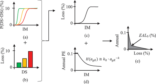
First, the respective fragility curve () is combined with the damage-to-loss function (), giving loss as a percentage of the monetary value of the building vs. the selected intensity measure, i.e. the vulnerability curves in . The vulnerability curves are then combined with the hazard curve defined to clause 2.1(4) of Eurocode 8 (CEN Citation2004) () to obtain the annual probability of exceedance (PE) of hazard intensity and the EALS, as shown in .
Finally, using the EALS, the pay-back time for each retrofit and for each level of seismic hazard is defined as the time to a financial break-even of the retrofit investment (Bournas Citation2018; Pohoryles et al. Citation2020). It can then be calculated as the ratio of the retrofit costs to the reduction in expected annual seismic losses ΔEALs according to EquationEq. (1)(1)
(1) :
3. Results
3.1. Building Analyses
3.1.1. Push-Over Analysis
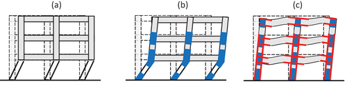
The push-over curves for the as-built, locally retrofitted and globally retrofitted structure are shown in . For the local retrofit an increase in the ultimate displacement up to 2.6% roof drift (+18.0%), and a moderate increase in base shear capacity (+20.2%) are observed. For the globally retrofitted specimen, instead, a substantial increase in strength (+43.1%) is additionally observed. The deformed shapes of the buildings at the ultimate displacement of the control specimen are shown in , indicating that the failure mechanism of the as-built control specimen and the locally retrofitted specimen are dominated by a single-storey or soft-storey failure, while the global retrofit achieves a more desired global mechanism with distributed deformations over the height of the building.
Figure 9. Push-over curves up to ultimate roof drift for the as-built and retrofitted RC buildings.
Figure 10. Deformed shapes of the (a) control, (b) local retrofit and (c) global retrofit at the NC target displacement.
For both retrofit schemes, the respective chord rotation limits in are not reached at the target displacements, while for the control structure, the shear capacity is reached at the drift corresponding to the DL limit state (0.76%), and the yield chord rotation (at 0.52% roof drift) and ultimate chord rotation (at 1.45% roof drift) are reached at levels of drift preceding the DL and NC limit states, respectively. This indicates that the as-built structure does not comply with the assessment criteria set-out in the guidelines, and that both the local and global retrofit are indeed adequately designed for the reference pga by means of increasing the chord rotation and shear capacities of the primary members.
3.1.2. Fragility Curves
The three building models were analysed by means of IDAs for a range of pga of 0.05–1.0 g to construct fragility curves for the deficient and retrofitted RC building. Based on the results of the IDAs, the fragility curves in terms of pga are obtained and are displayed in , for the reference building without retrofit, with local retrofit and global retrofit, respectively. , instead, show the same fragility curves derived in terms of Sa(T1). The parameters of the obtained fragility curves for pga and Sa(T1) are summarised in , respectively.
Figure 11. Fragility curves of the as-built, locally retrofitted and globally retrofitted building in terms of pga (a-c) and Sa(T1) (d–f).
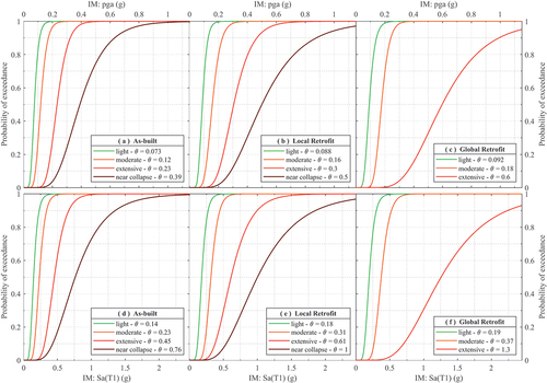
Table 7. Mean pga and standard deviation for the fragility curves of the as-built and retrofitted building.
Table 8. Mean Sa(T1) and standard deviation for the fragility curves of the as-built and retrofitted building.
It can be observed that the local retrofit improves the seismic performance of the building in terms of delaying the occurrence of the near collapse limit state to higher levels of seismic intensity. The light and moderate damage states also occur at larger intensity values, but the level of improvement is less. For the global retrofit, the improvements for the light and moderate damage states are similar to those observed for the local retrofit. However, for extensive damage, a clear improvement is observable as a consequence of the improved lateral load resisting mechanism activated in the building. A doubling of the mean intensity for the DS3 fragility curve is observed for the global retrofit compared to the local retrofit for both intensity measures. Moreover, the near collapse damage state is not obtained within a realistic range of ground motion intensities.
Finally, by the combination of the respective fragility curves with the damage-to-loss function (), the vulnerability curves for the three buildings are constructed. , clearly shows that for all levels of seismic intensity, the loss ratios in the globally retrofitted building are significantly reduced compared to those for the local retrofit scheme, and that both retrofit schemes result in lower loss ratios as compared to the non-retrofitted reference building.
Figure 12. Vulnerability curves of the as built control building, the local retrofit and the global retrofit.
3.2. Cost Benefit Analysis
For the cost-benefit analysis, the expected annual losses for the three building models are compared. The evaluated EALs as a fraction of the building cost for the three buildings are shown in for the three considered levels of seismic hazard. Given that retrofitting costs, as well as possible demolition and construction costs, are highly variable on the actual conditions and characteristics of the building, the values presented here should be considered for the sake of a relative comparison between the global and local retrofit, rather than to be absolute or precise values. It can be observed that the seismic losses increase, as expected, with increasing seismic hazard level. The losses for the non-retrofitted reference building are approximately three times larger for a pga of 0.25 g (EALS = 1.45%) as compared to a pga of 0.15 g (EALS = 0.44%). For the highest seismic hazard, the losses are 39.4% lower for the local retrofit (of EALS = 0.88%), but 53.8% lower for the global retrofit (EALS = 0.67%). Similar trends are observed for the two retrofits for the other levels of seismic hazard.
Figure 13. (a) Expected annual losses and (b) payback times for the three buildings for different levels of seismic hazard.
In terms of the return of investment, the results in indicate that payback times reduce with increased seismic hazard level. Faster pay back rates of the initial investment are obtained for the local retrofit as compared to the global retrofit for all levels of seismic hazard evaluated for Lisbon. For low levels of seismic hazard, the local retrofit has around two-thirds the payback time of the global retrofit (25.0 years versus 31.6 years). With increased seismic hazard, the relative difference reduces, with payback times of 9.2 and 10.2 years for the local and global retrofit, respectively, for a pga of 0.25 g. It is recognised that the estimated values of payback times may not reflect real retrofit interventions, for instance due to uncertainties in the retrofit cost and replacement cost estimations. Nevertheless, the results shown herein indicate trends that allow to compare the global and local retrofit interventions in locations of different seismic hazard.
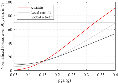
While payback times are one important financial aspect for retrofit investments, they do not reflect the actual reduction in seismic losses adequately. To extend the scope of the comparison of retrofit strategies beyond the seismic hazard scenario of Portugal, shows estimated normalised losses for the non-retrofitted and retrofitted buildings after 30 years for different levels of seismic hazard relevant for a European framework. It is assumed that the ratio of retrofit cost to building replacement cost remains unchanged. The 30 years period is selected arbitrarily as a service life extension due to retrofitting and can be seen as a conservative estimate. In terms of direct economic losses over the assumed service life of the retrofitted buildings, it is observed that the local retrofit shows cost-benefits for locations with a design pga of 0.13 g (10% of exceedance in 50 years), while the global retrofit becomes economically viable for pga values greater than 0.155 g. The benefit of the global retrofit scheme becomes clearly apparent for moderate and high seismic hazard, namely for design pga values over 0.20 g.
Figure 14. Normalised losses over 30 years for an extended range of seismic hazard for the as-built and retrofitted buildings.
4. Conclusions
In this study, an evaluation of a novel global FRP retrofitting design methodology is presented, aiming to improve the seismic behaviour of existing RC structures by significantly increasing the base shear capacity and changing the global failure mechanism to a more ductile one. The global retrofit scheme consists of a flexural retrofitting of columns via FRP strands, combined with shear strengthening of joints and columns, as well as selective weakening and strengthening of the beams for plastic hinge relocation.
A new fibre-element modelling approach for the global retrofitting scheme is proposed and validated against previous experimental data. With this model, the effectiveness of the retrofitting scheme is tested for a seismically deficient mid-rise reference structure, which is modelled before and after local and global retrofitting. Adaptive push-over analyses for the building prove that the inadequacies of the existing building can be eliminated by both retrofit schemes, which comply with the displacement-based assessment of Eurocode 8 – Part 3.
To compare the more elaborate and expensive global retrofitting scheme with the simpler local retrofit, looking at their effectiveness in improving the seismic performance of a building alone would be insufficient, a cost-benefit analysis is hence carried out. For this purpose, fragility curves are developed for the three building models using IDA. The fragility analysis confirms that the global retrofit scheme greatly outperforms the local retrofit scheme in terms of preventing the brittle collapse of the structure. Vulnerability functions are derived from the fragility curves using an appropriately chosen damage to loss function. These are used to calculate expected annual losses for three levels of seismic hazard, which are used as input to the cost-benefit analysis for comparing the retrofit schemes. It is shown that the global retrofit scheme provides a greater return on investment for moderate to high seismicity, but that the local retrofit scheme prevails for low seismicity.
Overall, the analyses provided in this paper highlight the potential of the global retrofitting scheme developed in Pohoryles et al. (Citation2018) and the proposed approach for modelling the retrofit can be seen as a way to ease the application of the retrofit scheme in real retrofit designs. To further allow their implementation, a detailed retrofit procedure will be presented in future work.
Disclosure Statement
No potential conflict of interest was reported by the author(s).
Data Availability Statement
The data that support the findings of this study are available from the corresponding author, upon reasonable request.
Additional information
Funding
References
- Akguzel, U., P. Quintana Gallo, and S. Pampanin. 2011. Seismic strengthening of a non-ductile RC frame structure using GFRP sheets. In Proceedings of the ninth pacific conference on earthquake engineering. Auckland, New Zealand. http://www.ir.canterbury.ac.nz/handle/10092/5363.
- Alsayed, S. H., Y. A. Al-Salloum, T. H. Almusallam, and N. A. Siddiqui. 2010. Seismic response of FRP-Upgraded exterior RC beam-column joints. Journal of Composites for Construction 14 (2):195–208. doi:10.1061/(ASCE)CC.1943-5614.0000067.
- Antoniou, S., and R. Pinho. 2004. Development and verification of a displacement-based adaptive pushover procedure. Journal of Earthquake Engineering 8 (5):643–61. doi:10.1080/13632460409350504.
- Baker, J. W. 2015. Efficient analytical fragility function fitting using dynamic structural analysis. Earthquake Spectra 31 (1):579–99. doi:10.1193/021113EQS025M.
- Bournas, D. A. 2018. Concurrent seismic and energy retrofitting of RC and masonry building envelopes using inorganic textile-based composites combined with insulation materials: A new concept. Composites Part B Engineering 148:166–79. doi:10.1016/j.compositesb.2018.04.002.
- Bournas, D. A., P. V. Lontou, C. G. Papanicolaou, and T. C. Triantafillou. 2007. Textile-reinforced mortar (TRM) versus FRP confinement in reinforced concrete columns. ACI Structural Journal 104 (6):740–48.
- Bousias, S., A.-L. Spathis, and M. N. Fardis. 2007. Seismic retrofitting of columns with lap spliced smooth bars through FRP or concrete jackets. Journal of Earthquake Engineering 11 (5):653–74. doi:10.1080/13632460601125714.
- Bousselham, A. 2010. State of research on seismic retrofit of RC beam-column joints with externally bonded FRP. Journal of Composites for Construction 14 (1):49–61. doi:10.1061/(ASCE)CC.1943-5614.0000049.
- Cardone, D., G. Gesualdi, and G. Perrone. 2019. Cost-benefit analysis of alternative retrofit strategies for RC frame buildings. Journal of Earthquake Engineering 23 (2):208–41. doi:10.1080/13632469.2017.1323041.
- CEN. 2004. BS EN 1998-1:2004 Eurocode 8. Design of structures for earthquake resistance - part 1:General rules, seismic actions and rules for buildings. London: BSI.
- CEN. 2006. BS EN 1998-3:2005 - Eurocode 8. Design of structures for earthquake resistance. Assessment and retrofitting of buildings. London: BSI.
- Chiu, C.-K., F.-P. Hsiao, and W.-Y. Jean. 2013. A novel lifetime cost-benefit analysis method for seismic retrofitting of low-rise reinforced concrete buildings. Structure and Infrastructure Engineering 9 (9):891–902. doi:10.1080/15732479.2011.631114.
- CNR. 2013. DT 200.R1/2013 - Guide for the design and construction of externally bonded FRP systems for strengthening existing structures - materials, RC and PC structures, masonry structures. Rome, Italy: CNR.
- CYPE. 2020. Gerador de Preços Na Construção - Portugal. http://geradordeprecos.cype.pt/reabilitacao.
- D’Ayala, D., A. Meslem, D. Vamvatsikos, K. Porter, T. Rossetto, H. Crowley, and V. Silva. 2014. Guidelines for analytical vulnerability assessment of low/mid-rise buildings – methodology. Vulnerability Global Component Project. www.nexus.globalquakemodel.org/gem-vulnerability/posts/.
- Del Vecchio, C., M. Di Ludovico, A. Balsamo, A. Prota, G. Manfredi, and M. Dolce. 2014. Experimental investigation of exterior RC beam-column joints retrofitted with FRP systems. Journal of Composites for Construction 18 (4). doi:10.1061/(ASCE)CC.1943-5614.0000459.
- Del Vecchio, C., M. Di Ludovico, A. Prota, and S. Pampanin. 2016. Repair costs analysis for case study buildings damaged in the 2009 L’Aquila earthquake. In Proceedings of the 2016 NZSEE conference. Christchurch, New Zealand. https://www.researchgate.net/publication/305789344_Repair_costs_analysis_for_case_study_buildings_damaged_in_the_2009_L%27Aquila_earthquake_2016_NZSEE_Conference.
- Engindeniz, M., L. F. Kahn, and A. H. Zureick. 2008. Performance of an RC corner beam-column joint severely damaged under bidirectional loading and rehabilitated with FRP composites. In Seismic strengthening of concrete buildings using FRP composites, 19–36. Farmington Hills, MI: American Concrete Institute. http://books.google.co.uk/books?hl=en&lr=&id=gI72a6OHeQIC&oi=fnd&pg=PA25&dq=FRP+engindeniz&ots=JYz9bJ-q59&sig=9IYHOyFV6mMrotwhfuHuPvw43CQ.
- European Commission. 2019. The European green deal - communication from the commission to the European Parliament, the European council, the council, the European economic and social committee and the committee of the regions. Brussels: European Commission.
- European Commission. 2020. COMMUNICATION FROM THE COMMISSION TO THE EUROPEAN PARLIAMENT, THE COUNCIL, THE EUROPEAN ECONOMIC AND SOCIAL COMMITTEE AND THE COMMITTEE OF THE REGIONS A Renovation Wave for Europe - greening our buildings, creating jobs, improving lives. Brussels.
- Ferreira, D. R. S. M., and J. A. O. Barros. 2006. CFRP-Based confinement strategies for RC columns-experimental and analytical research (April). http://repositorium.sdum.uminho.pt/handle/1822/5986.
- Filippou, F., and G. Fenves. 2004. Methods of analysis for earthquake- resistant structures. In Earthquake engineering, ed. Y. Bozorgnia and V. Bertero. Boca Raton, FL: CRC Press. http://www.crcnetbase.com/doi/10.1201/9780203486245.ch6.
- Furtado, A., H. Rodrigues, A. Arêde, and H. Varum. 2020. Cost-effective analysis of textile-reinforced mortar solutions used to reduce masonry infill walls collapse probability under seismic loads. Structures 28:141–57. doi:10.1016/j.istruc.2020.08.066.
- Gkatzogias, K., H. Crowley, A. Veljkovic, D. A. Pohoryles, H. Norlén, G. Tsionis, and D. A. Bournas. 2022. REEBUILD: Integrated techniques for the seismic strengthening and energy efficiency of existing buildings – prioritising EU regions for building renovation: Seismic Risk, energy efficiency, socioeconomic vulnerability. JRC128988. Luxembourg: Publications Office of the European Union.
- Gkournelos, P. D., T. C. Triantafillou, and D. A. Bournas. 2021. Seismic upgrading of existing reinforced concrete buildings: A state-of-the-art review. Engineering Structures 240:112273. doi:10.1016/j.engstruct.2021.112273.
- Hollaway, L. C. 2010. A review of the present and future utilisation of FRP composites in the civil infrastructure with reference to their important in-service properties. Construction and Building Materials 24 (12):2419–45. doi:10.1016/j.conbuildmat.2010.04.062.
- Iervolino, I., C. Galasso, and E. Cosenza. 2010. REXEL: Computer aided record selection for code-based seismic structural analysis. Bulletin of Earthquake Engineering 8 (2):339–62. doi:10.1007/s10518-009-9146-1.
- Kappos, A. J., and E. G. Dimitrakopoulos. 2008. Feasibility of pre-earthquake strengthening of buildings based on cost-benefit and life-cycle cost analysis, with the aid of fragility curves. Natural Hazards 45 (1):33–54. doi:10.1007/s11069-007-9155-9.
- Mander, J. B., M. J. Priestley, and R. Park. 1988. Theoretical stress-strain model for confined concrete. Journal of Structural Engineering 114 (8):1804–26. doi:10.1061/(ASCE)0733-9445(1988)114:8(1804).
- Mastroberti, M., D. Bournas, M. Vona, B. Manganelli, and V. Palermo. 2018. Combined seismic plus energy retrofitting for the existing RC buildings: Economic feasibility. In Proceedings of the 16th European conference on Earthquake engineering. Thessaloniki, Greece.
- Melo, J., D. A. Pohoryles, T. Rossetto, and H. Varum. 2021. Full-scale cyclic testing of realistic reinforced-concrete beam-column joints. MethodsX 8:101409. doi:10.1016/j.mex.2021.101409.
- Menegotto, M., and P. E. Pinto. 1973. Method of analysis for cyclically loaded reinforced concrete frames including changes in geometry and non-elastic behavior of elements under combined normal forces and bending moment. IASBE proceedings, Lisbon, Portugal.
- Orcamentos. 2022a. Orçamentos e Orçamentação Na Construção Civill, Sheet B0103 - Scaffolding. https://orcamentos.eu/fichas-de-rendimento-com-precos-de-andaimes/ (in Portuguese).
- Orcamentos. 2022b. Orçamentos e Orçamentação Na Construção Civill, Sheet C0203 - Demolitions. https://orcamentos.eu/fichas-de-rendimento-com-precos-de-demolicoes/ (in Portuguese).
- Palermo, V., G. Tsionis, and M. L. Sousa. 2018. Building stock inventory to assess seismic vulnerability across Europe. EUR 29257 EN. Luxembourg: Publications Office of the European Union. https://data.europa.eu/doi/10.2760/530683.
- Pantazopoulou, S., S. Tastani, G. Thermou, T. Triantafillou, G. Monti, D. Bournas, and M. Guadagnini. 2016. Background to the European seismic design provisions for retrofitting RC elements using FRP materials. Structural Concrete Journal of the Fib 17 (2):194–219. doi:10.1002/suco.201500102.
- Pohoryles, D. A. 2017. Realistic FRP seismic strengthening schemes for interior reinforced concrete beam-column joints. PhD., University College London.
- Pohoryles, D. A., C. Maduta, D. A. Bournas, and L. A. Kouris. 2020. Energy performance of existing residential buildings in Europe: A novel approach combining energy with seismic retrofitting. Energy & Buildings 223:110024. doi:10.1016/j.enbuild.2020.110024.
- Pohoryles, D. A., J. Melo, T. Rossetto, D. D’Ayala, and H. Varum. 2018. Experimental comparison of novel CFRP retrofit schemes for realistic full-scale RC beam–column joints. Journal of Composites for Construction 22 (5):04018027. doi:10.1061/(ASCE)CC.1943-5614.0000865.
- Pohoryles, D. A., J. Melo, T. Rossetto, H. Varum, and L. Bisby. 2019. Seismic retrofit schemes with FRP for deficient RC beam-column joints: State-of-the-art review. Journal of Composites for Construction 23 (4):03119001. doi:10.1061/(ASCE)CC.1943-5614.0000950.
- Porter, K. A. 2003. An overview of PEER’s performance-based earthquake engineering methodology. In Proceedings of ninth international conference on applications of statistics and probability in civil engineering, San Francisco, California.
- REBA. 1967. Governo D. Regulamento de Estruturas de Betão Armado - Decreto n.o 47723. Vol. 119. serie I. Lisbon, Portugal.
- Rossetto, T., and A. Elnashai. 2003. Derivation of vulnerability functions for European-type RC structures based on observational data. Engineering Structures 25 (10):1241–63. doi:10.1016/S0141-0296(03)00060-9.
- Seismosoft Ltd. 2018. SeismoStruct (version 2018). Pavia (PV) - Italy: Seismosoft Ltd.
- Sheikh, S. A., and Y. Li. 2007. Design of FRP confinement for square concrete columns. Engineering Structures 29 (6):1074–83. doi:10.1016/j.engstruct.2006.07.016.
- Silva, V., H. Crowley, H. Varum, R. Pinho, and L. Sousa. 2015. Investigation of the characteristics of Portuguese regular moment-frame RC buildings and development of a vulnerability model. Bulletin of Earthquake Engineering 13 (5):1455–90. doi:10.1007/s10518-014-9669-y.
- Smyth, A. W., G. Altay, G. Deodatis, M. Erdik, G. Franco, P. Gulkan, H. Kunreuther, H. Luş, E. Mete, N. Seeber, et al. 2004. Probabilistic benefit-cost analysis for earthquake damage mitigation: Evaluating measures for apartment houses in Turkey. Earthquake Spectra 20(1):171–203. doi:10.1193/1.1649937.
- Statistics Portugal. 2020a. Median value per M2 of dwellings sales (€) by geographic localization and category of housing unit; Quarterly. https://www.ine.pt/xportal/xmain?xpid=INE&xpgid=ine_indicadores&indOcorrCod=0009484&contexto=bd&selTab=tab2.
- Statistics Portugal. 2020b. Proportion of buildings with repair needed (%) by geographic localization (at the date of census 2011); Decennial. https://www.ine.pt/xportal/xmain?xpid=INE&xpgid=ine_indicadores&indOcorrCod=0006984&contexto=bd&selTab=tab2.
- Triantafillou, T. C. 2001. Seismic retrofitting of structures using FRPs. Progress in Structural Engineering and Materials 3 (1):57–65. doi:10.1002/pse.61.
- Vamvatsikos, D., and C. A. Cornell. 2002. Incremental dynamic analysis. Earthquake Engineering & Structural Dynamics 31 (3):491–514. doi:10.1002/eqe.141.
- Yurdakul, Ö., C. Del Vecchio, M. Di Ludovico, Ö. Avşar, and A. Prota. 2023. Fragility functions for fiber-reinforced polymers strengthened reinforced concrete beam-column joints. Engineering Structures 279:115570. doi:10.1016/j.engstruct.2022.115570.