Abstract
Passive and active limited-slip differentials are used in high-performance cars to optimize the torque distribution on the driving wheels for traction maximization, driving comfort, stability and active safety of the vehicle. In this paper, detailed and reduced dynamic models for the simulation of four kinds of differential are presented. The models refer to the limited-slip steering differential with two clutches. The model of the conventional differential, of the mechanical limited-slip differential and of the controlled limited-slip differential can be obtained by simplification. The detailed model allows the simulation of the internal phenomena that influence the differential dynamics. The reduced model focuses only on the main dynamic behaviour of the differential. Some simulations show the use of the reduced model to compare the effects of the four differentials on the vehicle dynamics.
1 Introduction
The differential (see below) is a mechanism that allows the driving wheels to rotate at different speeds as they follow different paths around a corner, and yet both transmit torque to the ground. They are mounted on every car. The role of the differential has come under much scrutiny due to its strong influence on vehicle stability, control and traction, see [Citation1].
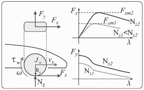
The importance of the differential can be understood by studying the typical behaviour of the tyres. shows the basic principles; see [Citation2] for further details. The dynamics of a wheel is given by:
To avoid the wheel spinning during cornering, the Vehicle Dynamic Control (VDC) and the Electronic Stability Program (ESP) systems [Citation3,Citation4] operate on the wheel brake pressures and on the engine in order to reduce the generated torque. This solution is good for safety, but it is not optimal in terms of performances: brakes dissipate energy and the reduction of the engine torque limits the longitudinal acceleration. Proper differentials are used to overcome these drawbacks.
The maximum longitudinal force Fxm that a tyre can transmit to the ground is limited. During cornering, the lateral acceleration causes a load transfer from the inner wheel to the outer wheel. Since the maximum longitudinal force Fxm of a tyre increases as the vertical load Nz increases (see ), the outer wheel can transmit more torque to the ground with respect to the inner one. This is the basic principle in understanding the differential control strategies. Note that different torques on the driving wheels introduce a steering effect on the car, therefore the controlled differentials can be seen as yaw control systems.
The conventional open differential delivers equal torque to each wheel, independently of the relative speed of the two wheels. During cornering, since the inner wheel has a lower vertical load, it starts spinning before the outer wheel. When that happens, the car starts understeering, the engine torque must be reduced to stop the wheel spinning, and therefore the longitudinal acceleration is limited.
The mechanical limited-slip differential uses one or two clutches to establish a Coulomb friction between the two differential output shafts (the two half-shafts). This friction is proportional to the total torque delivered to the differential case and it depends on the sign of the relative speed of the wheels; it subtracts torque from the fastest wheel and adds the same torque to the slowest wheel. In normal conditions the inner wheel is slower that the outer one, therefore any acceleration produces an unpleasant understeer effect (i.e. more torque is delivered to the inner wheel) with respect to the car equipped with the conventional differential. The benefits of a mechanical limited-slip differential are clear when the inner wheel starts spinning: its speed is greater than the speed of the outer wheel and therefore torque is transferred from the inner to the outer wheel. This automatically reduces wheel spinning, and more torque is transmitted to the wheel that has the higher vertical load, improving the acceleration performance of the car.
For the mechanical limited-slip differential, the amplitude of the friction depends on the input torque from the propeller shaft. The electronically controlled limited-slip differential (briefly electronic differential) is similar to the mechanical one, but uses an electro-actuated wet clutch and therefore more control flexibility is gained. Essentially, the electronic differential is activated (i.e. friction is added) only when the inner wheel tends to spin. In this way, the benefits of the mechanical limited-slip differential at high lateral acceleration are kept; at the same time the unpleasant understeer effect at low lateral acceleration disappears.
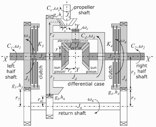
A further evolution is the electronically controlled ‘steering’ differential sketched in . This mechanical solution overcomes the common problem of the other differentials: it can transfer torque from the inner to the outer wheel even if the outer wheel is faster than the inner. The electronic steering differential has important effects on the vehicle stability thanks to its ability to steer the car by controlling the torque difference between the two half-shafts.
The limited-slip differentials have strong effects on vehicle safety, stability and performances. The development of proper control strategies requires differential and vehicle models for the simulation of the vehicle dynamics and for the testing of control algorithms. Moreover, the ESP control system must interact with the electronic differentials to achieve the best performance. The development of an integrated control strategy is under investigation and differential mathematical models for simulation are essential. This paper proposes three models of the electronically controlled steering differential with different levels of detail for the simulation of the differential behaviour and for the simulation of vehicle dynamics. Moreover, these models can be easily used to simulate the dynamic behaviour of all the other kinds of differentials.
The paper is organized as follows. The mechanical description and the detailed mathematical model of the steering differential are introduced in Section 2. The complex detailed mathematical model is then reduced and simplified in Section 3. The reduced model is used in Section 4 to compare in simulation the behaviour of the four kinds of differentials. Finally some conclusions are drawn.
2 Steering Differential with Control Clutches
A simplified mechanical scheme of a steering differential is shown in . The propeller shaft Js transmits the torque Cs from the engine (through the gearbox) to the differential case Jd . The differential case rotates around the X – X axis and drags the planet pinions J γ (for simplicity only one planet pinion is shown in ). The planet pinions are connected to the two half-shafts J 1 and J 2 by means of the two sun pinions. Let us define the following gear ratios:
The structure described till now is the same as the conventional open differential. The electronically controlled steering differential adds the horizontal return shaft J 6, the two return wheels J 3 and J 4, and the two clutches K 3 (between J 3 and J 1) and K 4 (between J 4 and J 2). Due to the gear ratios, the following relations hold:
To introduce the dynamic equations of a steering differential, let us define the function γ(x,g,h) as follows:
The function γ(x,g,h) is used to describe both the torsional stiffness and the lash of a mechanical gearing. The parameter h represents the torsional stiffness and the parameter g describes the semi-amplitude of the lash. An ideal gearing with constant ratio has g = 0 and h→∞.
Let θ i (for i = 1, 2, 3, 4, 6), θ d , θγ and θ s denote the angular positions of the mechanical elements shown in . The proposed model of the car differential shown in is described by the following dynamic equations:
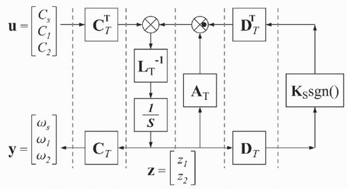
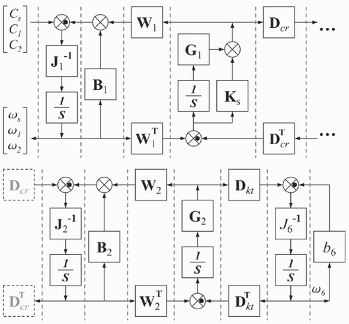
The linear friction bi ω i can be easily substituted by a generic non-linear friction bi (ω i ). The dynamic system defined by Equationequations (2) Equationequations (2) can be simulated by using the block scheme shown in . The basic idea of this scheme is to use the power interaction between subsystems as the basic concept for modelling [Citation5,Citation6]. The dashed lines represent the power ports between the subsystems and the inner product of the two vectorial variables involved in each dashed line of the graph has the physical meaning of the power flowing through the section. The black dot means a change of sign. The presence of the integrators (integral causality) and the absence of derivators (differential causality), see [Citation7], allow the reliable simulation of this scheme using every computer simulation. The matrices in the scheme of are defined as follows:
Figure 3. Scheme for the simulation of the steering differential corresponding to Equationequations (2).
3 Model reduction
The model of corresponding to the system (2) requires a demanding computational effort to be simulated for two reasons. First the gears are usually almost ideal; therefore the stiffness values hs, h 1, h 2, h 3, h 4 and h 6 are very high. High stiffness values involve wide torque variations for small torsion angles, and this slows down the simulations because the simulation step size must be reduced to achieve reliable results.
The second reason is the presence of the two terms K 3 sgn (ω3 – ω1) and K 4sgn(ω4–ω2) due to the Coulomb friction. When the difference (ω i – ω j ) becomes zero, the term Ki sgn(ω i –ω j ) starts switching between ± Ki , and to achieve reliable simulation results the simulation step size must be as small as possible. The problem of the proper simulation of Coulomb friction is a well-studied subject and various solutions can be found in the literature. A survey of friction models and simulation techniques concerning the Coulomb friction is given in [Citation8]. Some energy based accurate solutions can be found in [Citation9]. The solution proposed in this paper differs from the preceding thanks to a state space transformation that allows us to deal with the Coulomb friction without the need of model switching, pre-slip velocities, or hybrid resistive ports. The simulation results are exact and the simulations only require the detection of the zero relative velocity. Moreover, the solutions presented in [Citation8] and [Citation9] are not applicable directly to the steering differential.
From a system theory point of view, the steering differential is a so-called Variable Dynamic Dimension System (see [Citation10]). Due to strong non-linearities (i.e. Ki sgn(ω1–ω j )), this kind of system changes its dynamic dimension during normal system operations. Variable dynamic dimension systems are quite common in mechanical devices with Coulomb friction, such as clutches [Citation11], gearboxes [Citation12], brakes and limited-slip differentials. From a mathematical point of view, the system order reduction means that some state variable derivatives are constrained to remain zero until some dynamical conditions are satisfied. In the steering differential, if the friction coefficient K 3 (or K 4) is high enough, the two axles J 1 and J 3 (or J 2 and J 4) are constrained to rotate at the same speed: ω1 = ω3 (or ω2 = ω4) and the dynamic dimension is reduced by 1. When the dynamic dimension in the real system reduces, the term K 3 sgn (ω1 – ω3) (or K 4 sgn (ω2 – ω4)) in model (2) starts switching and the computational effort rises dramatically. This problem can be solved using twice the algorithm presented in [Citation10] for the two axles pairs J 1, J 3 and J 2, J 4. Nevertheless, the computational time remains affected by the high stiffness values.
This section presents step-by-step a model reduction that preserves the main dynamic behaviour of the steering differential and reduces significantly the simulation computational effort without affecting the reliability of the results.
First of all, since the gears are almost ideal, the lashes gs, g 1, g 2, g 3, g 4 and g 6 are very small and their effect can be neglected. Reducing the lashes gs, g 1, g 2, g 3, g 4 and g 6 to zero, the function γ(x,g,h) simplifies as follows:
The system (3) can be simulated by using the block scheme of with the two matrices G 1 and G 2 changed as follows:
Let us rewrite system (3) in the following compact matrix form:
Assuming ideal gears, the stiffness values h 1, h 2, h 3, h 4, h 6 and h 5 tend to infinity, the last six equations of system (3) lead to six algebraic constraints:
Considering the algebraic Equationequations (5) it is possible to find a rectangular state space transformation x = T z that reduces system (4) from 14th to the second order:
The system (7) is simpler than system (4) because ideal gears have been considered, but the computational effort still remains demanding due to the presence of the two terms Ki sgn (ω i – ω j ). The state space transformation T gives to system (7) an important property that allows us to solve this problem. Since both D T and K s are diagonal, the vector
Let τ i denote the equivalent control associated to the switching term ki sgn (zi ), that is the time mean value of the term ki sgn (zi ). The equivalent control can be seen as the average value of the sliding variable and the system dynamics does not change if the sliding term ki sgn (zi ) is replaced by the corresponding equivalent control τ i .
When a sliding condition arises on the variable zi , the function ki sgn (zi ) holds zi = 0, therefore the corresponding equivalent control τ i can be computed by solving (11) with
| 1. | Let zi ≠ 0 and z 2 ≠ 0. Since the state variables are not zero, sliding mode conditions cannot arise and the system dynamics is given (and simulated) by (11). | ||||
| 2. | Let z 1 ≠ 0 and z 2 = 0. A sliding mode can arise on variable z 2. The corresponding equivalent control τ2 is the control necessary to hold the condition z2 = 0, therefore it can be computed by replacing k 2 sgn (z 2) with τ2 in (11) and imposing the condition | ||||
The equivalent control τ2 necessary to hold the condition z2 = 0 is then:
(3) Let z 1 = 0 and z 2 ≠ 0. The solution is symmetric with respect to case (2).
(4) Let z 1 = 0 and z 2 = 0. The solution is similar to case (2). A sliding mode can arise on either z1 or z2 or both. The two corresponding equivalent controls τ1 and τ2 are computed solving the system:
Since the two conditions | τ i | ⩽ ki must be satisfied, the dynamics of system (11) when z 1 = 0 and z 2 = 0 is given (and simulated) by:
This case seems to be the most complex, but it is less interesting from the simulation's point of view because the condition z 1 = z 2 = 0 means that the differential does not rotate and the car is at rest.
Please note that the simplicity of the proposed algorithm is due to the proper congruent transformation T. The steering differential model is the most complex among the other kinds of differential. Mathematically this means that the dynamic behaviour of all car differentials [Citation14] can be simulated by the steering differential model of . In fact, the inertias Jd, J 3, J 4 and J 6 can be merged to represent the case inertia of a conventional, mechanical limited-slip or electronic limited-slip differential. Moreover, thanks to the wider operating region of the steering differential, the torque imbalance between the two half-shafts of the other differentials can be easily obtained with proper values of the two friction coefficients K 3 and K 4.
4 Simulation results and comparisons
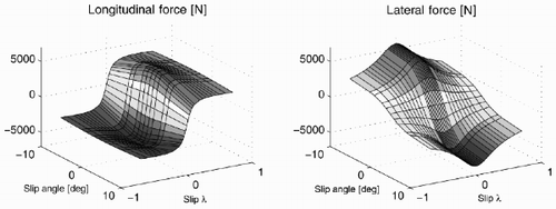
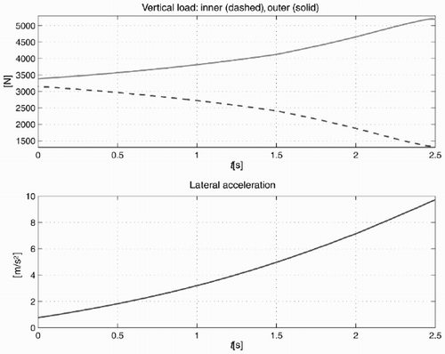
The simulations described in this section refer to a car cornering a 10m constant radius left curve at constant longitudinal acceleration ax = 0.3g. In the sequel the behaviour of the four kinds of differential are compared using the model (7). shows the vertical loads and the lateral acceleration of the car around the corner. The tyres are described by Pacejka's formula [Citation2] with parameters corresponding to a commercial tyre; see .
Figure 5. Vertical load and lateral acceleration for a 10 m radius curve at longitudinal acceleration ax = 0.3g.
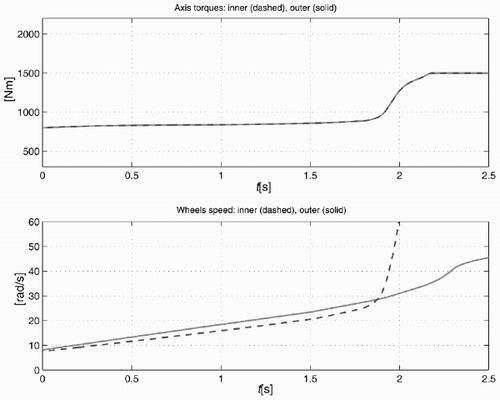
The torques delivered to the two half-shafts and the wheel speeds when the conventional differential is used are shown in . For t < 1.8s the speed and the lateral acceleration are low, both driving wheels well adhere to the road surface and the outer wheel rotates at a higher speed than the inner one. This is the normal driving condition. For t > 1.8s the vertical load on the inner wheel becomes low enough to cause the inner wheel to spin. This spinning is due to the fact that the torque on the two half-shafts is the same.
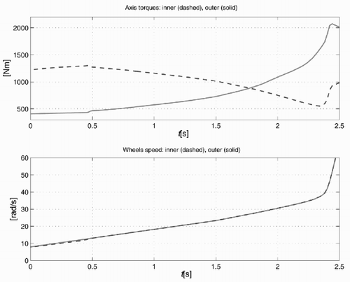
The mechanical limited-slip differential avoids the inner wheel spinning because for t > 1.8s more torque is delivered to the outer wheel, see . The two wheel speeds are equal because the differential is locked due to the total torque delivered to the differential case. The drawback is that for low lateral acceleration the car has a tendency to understeer (with respect to a car equipped with a conventional differential) because the inner wheel gets more torque.
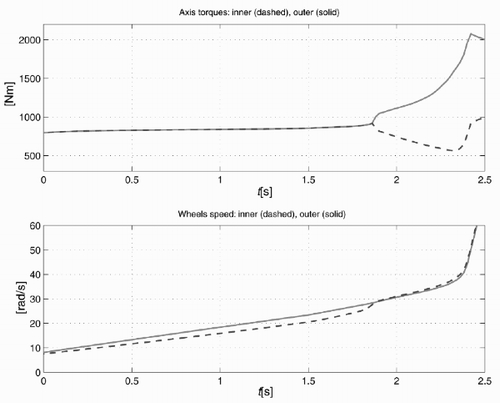
The understeer drawback is solved with the electronic limited-slip differential as shown in . The differential is locked only for t > 1.8s, as soon as the inner wheel speed becomes greater than the outer one. For low lateral acceleration the behaviour is the same as the conventional differential.
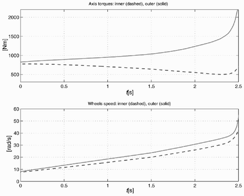
Finally, underlines the capability of the electronically controlled steering differential to deliver the desired torque on the two wheels when condition (1) is satisfied. In the simulation of , the torque difference between the two wheels follows the lateral load transfer.
5 Conclusions
A detailed dynamic model of an electronically controlled steering differential has been proposed. To obtain faster and still reliable simulations, reduced dynamic models have been obtained by a proper state-space transformation and simplification of the detailed model. The steering differential models allow the simulation of the dynamical behaviour of the most common car differentials. The proposed reduced model has been used to compare the effects of four kinds of differentials on the vehicle dynamics.
References
References
- Wright P 2000 Formula 1 Technology SAE Inc. Warendale PA ISBN 0-7680-0234-6 pp. 82 – 91
- Pacejka HB 2002 Tyre and Vehicle Dynamics SAE Inc. Warendale PA ISBN 0-7680-1126-4
- van Zanten AT Erhardt R Pfaff G 1995 VDC: The Vehicle Dynamics Control System of Bosch, SAE International Congress and Exposition, Detroit, Michigan, February 27–March 2, 1995, no 950759
- van Zanten AT 2000 Bosch ESP Systems: 5 Years of Experience, SAE Automotive Dynamics & Stability Conference, Troy, Michigan, May 15–17, 2000
- Karnopp DC Rosemberg RC 1975 System Dynamics: A Unified Approach New York Wiley
- Zanasi R 1991 Power Oriented Modelling of Dynamical System for Simulation, IMACS Symposium on Modelling and Control of Technological System, Lille, France, May 1991
- Breedveld , PC . 2004 . Port-based modeling of mechatronic systems . Mathematics and Computer in Simulations , 66 : 99 – 127 .
- Armstrong-Hélouvrya , B , Dupont , P and Canudas De Wit , C . 1994 . A survey of models, analysis tools and compensation methods for the control of machines with friction . Automatica , v.30 ( 7 ) : 1083 – 1138 .
- Breedveld PC 2000 An alternative model for static and dynamic friction in dynamic system simulation Preprints First IFAC Conference on Mechatronic Systems, Darmstadt, Germany, 2000 pp. 717 – 722
- Zanasi R Sandoni G Morselli R 2001 Simulation of a variable dynamic dimension systems: the clutch example European Control Conference (ECC), Oporto (Portugal), September 2001
- Zanasi R Visconti A Sandoni G Morselli R 2001 Dynamic modeling and control of a car transmission system International Conference on Advanced Intelligent Mechatronics, Como, Italy, 2001
- Zanasi R Sandoni G Visconti A 2002 Dynamic model and control of a gearbox system Mechatronics Forum International Conference, Enschede (Netherlands), June 2002
- Utkin , VI . 1977 . Variable structure systems with sliding modes . IEEE Transactions on Automatic Control , 22 : 212 – 222 .
- Zanasi R Sandoni G Morselli R 2003 Mechanical and active car differential: detailed and reduced dynamic models Proceedings of the Symposium on Mathematical Modelling – MATHMOD'03, Vienna, Austria, February 2003 pp. 1011 – 1020
