Abstract
The electric power steering (EPS) mechanism ensures improved vehicle safety and fuel economy. The development of a concurrent simulation technique and a simulation integration technique for analysing an EPS control system with a dynamic vehicle system is described in this paper. A full vehicle model interacting with an EPS control algorithm was concurrently simulated on a single-bump road condition. The dynamic responses of the vehicle chassis and the steering system resulting from impact with the road surface were evaluated and compared with experimental data obtained at the proving ground. Reasonable agreement was obtained for tie-rod load, rack displacement, steering wheel torque, and tyre centre acceleration. The concurrent simulation capability was employed for EPS performance evaluation and calibration as well as for vehicle-handling performance integration and synthesis.
1. Introduction
Electric power steering (EPS) is an advanced system in which an electric motor is used to assist steering. It eliminates the need for a hydraulic power steering pump, hoses, hydraulic fluid, drive belt, and pulley in the engine so that the system is lighter and more compact system than a hydraulic system. Since EPS is an on-demand system which operates only when the steering wheel is turned, the fuel efficiency of vehicles equipped with such a system is 3% better than that of vehicles equipped with an equivalent-output hydraulic system Citation1. Therefore EPS is more energy efficient and environmentally friendly, and is being increasingly used in vehicles.
The evaluation of EPS performance through simulation requires an accurate and robust analytical EPS model. Earlier work has focused mainly on developing the EPS control algorithm. Okamoto et al. Citation2 investigated the influence of inertia and friction of the motor used in EPS on the driver's feel. Smith et al. Citation3 proposed that a power steering shudder can be analysed as a control system with a closed-loop limit cycle caused by the interaction of the chassis and the steering system. A metric for determining the shudder propensity of a vehicle was created. Although Olson and Milacic Citation4 used a computer code to simulate a quarter-vehicle model interacting with several control systems (steering, brake, and traction), most of the previous research did not account for the interaction of all the chassis variables involved while monitoring the vehicle and generating control signals. Patwardhan et al. Citation5 studied the fundamental issues of automatic steering control for highway driving in a general framework. A linearized vehicle model was used to simulate the lateral control response to follow a reference along the lane centre during automatic steering. Badawy et al. Citation6 developed a reduced-order EPS model to investigate the dynamic characteristics of the system. Roy Citation7 developed a theoretical driver steering behaviour model, and combined it with a two-mass model of vehicle yaw and lateral yaw dynamics to study the effect of yaw rate feedback on vehicle stability. Kim and Song Citation8 developed EPS control logic for reducing the steering torque by a driver, realization of various steering feels, and improvement in return-to-centre performance. Amberkar et al. Citation9 studied the performance of the steer-by-wire system with respect to feel, responsiveness, and stability.
With the increasing complexity of automotive mechanisms and other critical vehicle chassis structures, debugging and refining the control algorithm is becoming more difficult. To date, the dynamic responses of a vehicle chassis system equipped with EPS have not been analytically investigated. Two simulation techniques, co-simulation and simulation integration, to investigate a dynamic vehicle model with an EPS control system are developed in this paper. A full vehicle model interacting with EPS control algorithm is concurrently simulated for a single-bump road profile. The dynamic responses of the vehicle chassis and the steering system resulting from impact with the road surface are evaluated and compared with experimental data obtained at a proving ground. This integrated method allows engineers to determine whether the overall design of the vehicle and EPS meets design targets without the need for extensive prototype testing which is expensive and time-consuming.
2 Model development
2.1 Overview of the EPS model
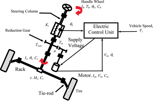
EPS incorporates a steering gear, an assist mechanism, a brushless motor, and an electronic controller to provide responsive steering assist. Two primary inputs (driver torque on the steering wheel and vehicle speed signal), together with other system variables, are continuously fed into an electronic control module which determines the direction and amount of steering assist. As the driver turns the steering wheel, a torque/angle is exerted on it which represents the intention of the driver to move the vehicle. Based on the road conditions and the desire of the driver to turn the vehicle, a torque sensor located between steering wheel and motor detects the steering torque if there is a discrepancy between the intended angle at the steering wheel and the actual angle of the front tyre. The motor current is determined based on this torque sensor signal. An assistant torque, which is an input to the steering shaft, is obtained by multiplying the motor torque by the gear ratio. This assistant torque together with the torque applied to the steering wheel by the driver rotates the steering shaft against the reaction torque of the tyres and the frictional loss of the steering mechanism. The assistant torque reduces the stress in steering column and the effort exerted by the driver. A typical EPS mechanism and block diagram Citation10 is shown in .
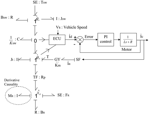
2.2 Bond graph modelling
shows the bond graph model with derivative causality for a column-type EPS system incorporated with the EPS control algorithm. Here the inertia element representing mass M r of the rack is assigned as the derivative causality. According to the principles of bond graph modelling Citation11, the appropriate causality for a storage element is integral causality, where the cause is integrated to generate the effect. Thus integral causality implies that the past data of cause or history function is integrated to arrive at an effect felt at present, whereas differential causality requires differentiation of the cause at present (which cannot be established as the future is unknown) to arrive at an effect. Hence differential causality makes the system dependent on future, as if the system is being dragged towards a predestined configuration, and thus adds specific constraints to the dynamics of the system. Thus derivative causality results in unnecessary loops which create complexity while simulating the model.
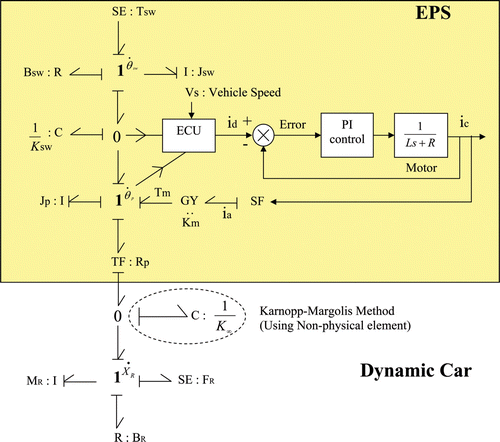
shows the bond graph model without derivative causality for a column-type EPS system. The derivative causality is removed by the Karnopp – Margolis method Citation12 using a non-physical element. Therefore a zero junction with a capacitance element representing the stiffness of the rack and pinion is inserted as highlighted in .
2.3 Full vehicle model
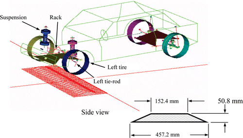
A full vehicle model was created using ADAMS version 10.0 and DADS version 9.5.1. This multi-body dynamic model, which comprises non-linear elastic front and rear suspension, a steering system including the rack and its joints with tie-rods, and a tyre model with combined longitudinal and lateral force calculation, was originally developed for simulating vehicle dynamics. The vehicle model is driven by speed applied to the centre of gravity of the vehicle. The drive path of vehicle is controlled by displacement of the rack. Overall, this full vehicle model processes 347 kinematic degrees of freedom. A single-bump road profile was created to study the chassis dynamic responses resulting from road surface impact force. To simulate the higher unbalanced impact force on the chassis, only the tyres (front and rear) on the driver's side hit the bump. The bump is 50.8 mm high and 457.2 mm wide, corresponding to the road test conditions at the proving ground ( ).
3 Integrated analysis
The function of the EPS system in a vehicle is to provide the desired rack displacement and velocity based on the driver steering input, vehicle velocity, and rack force. The modelling and dynamic performance analysis of a vehicle equipped with EPS requires a robust and accurate code. Multi-body system codes like ADAMS are suitable for studying the dynamic characteristics of the vehicle chassis. Although a basic controller like PID can be implemented with ease in ADAMS, sophisticated controls like EPS system require Matlab/Simulink or an equivalent software capability. However, generating a single-code Matlab/Simulink full vehicle model is difficult because of the complexity of the EPS control algorithm and the large number of degrees of freedom. In this study, ADAMS and Matlab Version 5.3.1 are utilized to model a full vehicle equipped with an EPS control system. ADAMS performs the integration of dynamic vehicle model and Matlab executes the control integration of the EPS system. This technique of simultaneous execution of two software packages is called concurrent simulation.
3.1 Simulation approaches
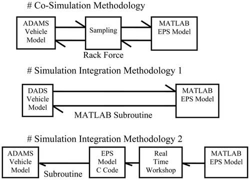
In this section we analyse the concurrent simulation technique and the simulation integration technique. shows the different simulation techniques that can be used.
3.1.1 Concurrent simulation technique
In concurrent simulation, the input and output parameters of both software packages, Matlab for EPS and ADAMS for the multi-body vehicle model, need to be defined. The entire coupling is performed by a subroutine in Matlab which opens the pipes for the bidirectional data exchange and starts ADAMS at every time step. During the simulation, both packages take simultaneous time steps. Each package independently computes the solution for its respective models. At the beginning and end of each step, the packages exchange input – output signal data. The concurrent simulation method is suitable for the full vehicle model which is numerically very stiff and cannot be integrated by control application.
3.1.2 Matlab and DADS subroutine integration
In simulation integration, DADS and Matlab are used to model a full vehicle equipped with an EPS control system. The DADS model is prepared as a Matlab subroutine and Matlab takes over the integration. DADS calculates the outputs of interest from the dynamic vehicle model and Matlab executes the control integration of the EPS system. DADS with a full vehicle model is represented as a Matlab subroutine ‘S-function’.
3.1.3 ADAMS and ADAMS subroutine C code
In this integration method, a special toolbox in Matlab/Simulink called the Real Time Workshop (RTW) is used to generate a C code for interface usage. The RTW of Matlab/Simulink has a function, ‘make_rtw’, which converts a Simulink EPS model to C code. The files generated consist of several C codes and header files which are automatically built by Matlab. However, the C codes contain unnecessarily lengthy statements and complex programs although the Simulink model is simple. When the generated C codes are transferred from a PC to a Unix the C codes become unexecutable because of the different cross-platform capabilities of PC and Unix. In addition, the C code has its own integrator, ‘ode2.c’, which needs to be separated and integrated into ADAMS. This separation and integration adds to programming complexity.
3.2 Interface variables
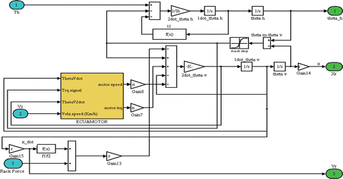
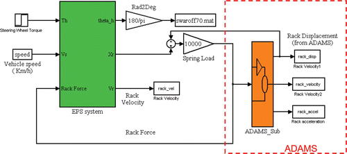
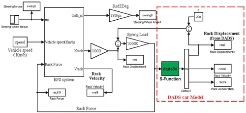
The translational force applied to the rack resulting in rack displacement determines how far the vehicle turns. Therefore rack force is an external input into the vehicle model. The resultant displacement and velocity of the rack are external outputs of the control laws. illustrates the control block diagram of EPS system, and and show the block diagrams of the fully integrated model. They also show the interface for concurrent simulation and simulation integration between the full vehicle model and the EPS control module.
The inputs to the EPS system include steering wheel torque, vehicle speed, and rack force. The outputs of EPS system are the resultant angular position and velocity of the steering wheel together with displacement and velocity of the rack. The step steering torque input is applied at the steering wheel such that it turns the vehicle in the desired circular path corresponding to the road curve on the proving ground. The shaded block denoted ‘ADAMS_sub’ in is a subsystem which consists of the full vehicle model created using ADAMS. The shaded block denoted ‘S-Function’ in is a subsystem which consists of the full vehicle model created using DADS.
3.3 Simulating the model
After defining all vehicle parameters in the Matlab prompt, the selection of ‘Simulation’ from the toolbar on the Simulink palette brings up a pop-up menu. Clicking on ‘Parameter’ enables a simulation parameter dialogue box to be viewed. The simulation parameters are defined by entering the start time and end time, selecting the type of the solver to be employed, and closing the dialogue box. During the interaction mode, a new ADAMS/View window appears which enables graphical displays to be obtained by clicking the ‘Start’ of simulation available on the Simulink palette. ADAMS accepts the control inputs from Matlab and the model moves in response to them. ADAMS then provides the azimuthal position and rotor velocity information to Matlab. This simulation process creates a closed loop in which the control inputs from Matlab affect the ADAMS simulation, and the ADAMS output affects the control input levels. ADAMS/View closes automatically after the simulation is performed. In the batch mode, ADAMS shows the numerical output lists for the defined inputs and outputs at the start of the simulation. The simulation run is much faster. Any of the data generated in Matlab can be plotted on the Matlab prompt showing the time history of input to ADAMS. The detailed responses for the ADAMS vehicle model can be also plotted in ADAMS/View.
4 Simulation results and comparison with experiments
The simulation result and its correlation with experimental data are discussed in this section. A prototype vehicle was tested three times on the proving ground. It was driven at a speed of 32 km/h on a circular path with a diameter of 65.8 m. As the lateral acceleration of the vehicle reached 0.25g, the tyres on the driver's side of the vehicle (front and rear) were driven over a single bump. The dimensions of the single bump are shown in . For vehicle performance evaluation, only the left side tyres were driven over this single bump and generated a larger unbalanced load on the vehicle chassis as a result of impact with the road surface. Accelerometers mounted on several locations inside the vehicle acquired the dynamic characteristics of the vehicle chassis under these driving and road conditions.
A full dynamic vehicle model integrated with the EPS control algorithm is simulated under the same driving and road conditions as the tests conducted on the proving ground. The vehicle hits the bump at 1.85 s on the left-front tyre and then on the left-rear tyre. The entire simulation time is 3 s and the sampling rate is 0.005 s, which is about five times as fast as the required controller bandwidth. The vehicle model and the EPS control algorithm exchange input – output signal data every 0.005 s, such that 600 time steps are executed. Matlab 6.5 and ADAMS co-simulation in the HP Unix platform is executed in 11 min.
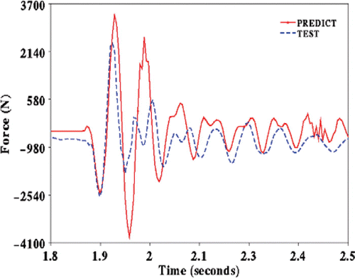
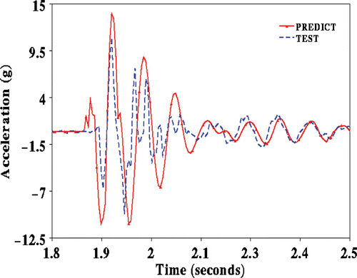
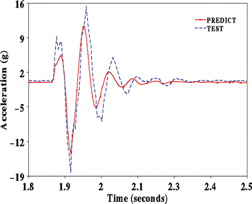
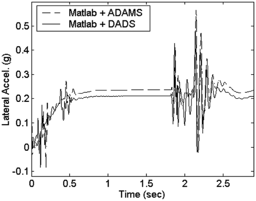
The comparisons between the simulation results and the test data are focused on the time of vehicle impact on the single bump. shows the predicted and test results of left-front tie-rod load in time domain. The left-front tyre centre accelerations in the directions of fore – aft and vertical are shown in and , respectively. At the first valley illustrated in , the model overpredicts 61.2% of the test value (−10.8g versus −6.7g). As illustrated in and , only one spike occurs at around 2 s during simulation while two spikes are measured during experiment. This discrepancy might be due to the sampling time during concurrent simulation.
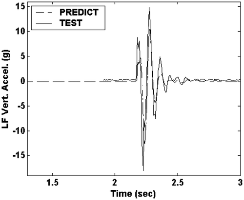
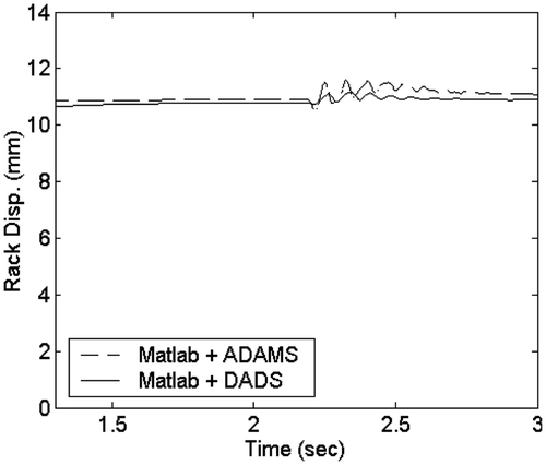
shows the comparison of predicted and test results of the left-front tyre centre accelerations in the vertical directions when the vehicle hits the bump at 2.25 s on the left-front tyre and then on the left-rear tyre. Overall, the simulation results correlate quite well with the experimental data in terms of the occurrence of spikes and their magnitudes. and compare the results of co-simulation with that of simulation integration. shows a small difference and shows a small error which may be due to different integrators. In concurrent simulation two integrators were executed, but in simulation integration only the Matlab integrator was executed. The simulation integration method proves to be time consuming as 24 h are required for complete execution.
5 Conclusion
Modelling the EPS system using a single code is a difficult task because of the large number of degrees of freedom of the full vehicle model and the complexity of the EPS control algorithm. Therefore in this paper concurrent simulation and simulation integration techniques have been adopted in which two computer codes are performed concurrently to resolve the multi-body dynamics (full vehicle model) and the EPS control algorithm. Thus a full vehicle model integrated with the EPS control algorithm has been developed which predicts the dynamic characteristics of the vehicle chassis and steering system subjected to road surface conditions. The integrated vehicle model is simulated on a circular path with a single-bump profile. The dynamic responses of the vehicle chassis and steering system resulting from impacts with the road surface are evaluated and compared with experimental test results. The comparisons show reasonable agreement for tie-rod load, rack displacement, steering wheel torque, and tyre centre acceleration.
The technical methodology for concurrent simulation and simulation integration has been investigated with respect to evaluating its capability to integrate the full vehicle model and a complex control algorithm like that of EPS system. Concurrent simulation using Matlab and ADAMS proves to be the best approach; ADAMS determines only the rack force input and not the rack displacement. The simulation integration technique using Matlab and DADS produced accurate results but the run time was found to be very long.
The co-simulation method developed here allows engineers to determine whether the overall design of a vehicle equipped with EPS meets design targets without the necessity for extensive prototype testing which is expensive and time-consuming. These results help engineers to identify critical system parameters influencing EPS performance under various driving conditions. Thus concurrent simulation promises to be a productive method for complex mechanism integration as well as for control systems.
Acknowledgements
This work was partially supported by a grant from the 2004 Research Fund of Andong National University and Brain Korea 21. The first author expresses his great appreciation to Professor Dean Karnopp, a true scholar, for his valuable support and guidance at the University of California, Davis.
References
- Nakayama , T. and Suda , E. 1994 . The present and future of electric power steering . International Journal of Vehicle Design , 15 : 243 – 254 .
- Okamoto , K. , Chikum , I. , Saio , N. and Miyazak , H. 1989 . “ Improvement of driver's feel of electric power steering ” . In SAE Paper 89-0079 , Warrendale, PA : Society of Automotive Engineers .
- Smith , J. M. , Ferries , G. R. and Arbanas , R. L. 1995 . “ An analytical control systems approach to steering shudder ” . In SAE Paper 95-0125 , Warrendale, PA : Society of Automotive Engineers .
- Olson , W. W. and Milacic , D. 1996 . Development of anti-lock braking traction and control systems of the advanced technology demonstrator II using DADS simulation code . International Journal of Vehicle Design , 17 : 295 – 316 .
- Patwardhan , S. , Tan , H. and Guldner , J. A general framework for automatic steering control: system analysis . IEEE Proceedings of the 1997 American Control Conference . pp. 1598 – 1602 .
- Badawy , A. , Zuraski , J. , Bolourchi , F. and Chandy , A. 1999 . “ Modeling and analysis of an electric power steering ” . In SAE Paper 01-0399 , Warrendale, PA : Society of Automotive Engineers .
- Roy , M. 2000 . “ Variable effort steering for vehicle stability enhancement using an electric power steering system ” . In SAE Paper 01-0817 , Warrendale, PA : Society of Automotive Engineers .
- Kim , J. H. and Song , J. B. 2002 . Control logic for an electric power steering system using assist motor . Mechatronics , 12 : 447 – 459 .
- Ambrekar , S. , Bolourchi , F. , Demerly , J. and Millsap , S. 2004 . “ A control system methodology for steer by wire systems ” . In SAE Paper 01-1106D , Warrendale, PA : Society of Automotive Engineers .
- Jang , B. C. Co-Simulation technology development for free control of SUV vehicle equipped with electric power steering . Proceedings of the KSME Kyungbuk Spring Conference, Korean Society of Mechanical Engineers . pp. 29 – 36 .
- Karnopp , D. C. , Margolis , D. L. and Rosenberg , R. C. 1999 . System Dynamics: A Unified Approach , (2nd edn) , New York : John Wiley .
- Zeid , A. and Chung , C. H. 1992 . Bond graph modelling of multibody systems: a library of three-dimensional joints . Journal of the Franklin Institute , 329 : 605 – 636 .
- Kim , H. S. and You , S. S. 2001 . Estimation of vehicle side slip angle for four-wheel steering passenger cars . Transactions on Control, Automation and Systems Engineering , 3 : 71 – 76 .
- Kim , D. H. , Shin , B. K. , Yi , K. S. and Lee , K. I. Observer based estimation of driving resistance load for vehicle longitudinal motion control . Conference on KACC . pp. 185 – 188 .
- Nguyen , T. T. , Nguyen , V. G. and Kim , S. B. 2000 . Control of active suspension system by using H∞ theory . ICASE Transactions on Control, Automation and System Engineering , 2 : 1 – 6 .
Appendix
The parameters of the Saturn sports utility vehicle used in the simulation were as follows.
Nomenclature
| C h | = |
damping of steering wheel |
| K t | = |
spring rate of torsion bar |
| C m | = |
damping of motor |
| M r | = |
mass of rack-and-pinion mechanism |
| C r | = |
damping of rack-and-pinion mechanism |
| r | = |
radius of pinion |
| n | = |
gear ratio |
| C v | = |
damping of steering shaft |
| I g1 | = |
inertia of drive gear |
| T h | = |
input torque |
| I g2 | = |
inertia of driven gear |
| T m | = |
motor torque |
| I h | = |
inertia of steering wheel |
| I m | = |
inertia of motor |
| I sum | = |
inertia of entire mechanism |
| V m | = |
motor speed |
| I v | = |
inertia of steering column |
| T sum | = |
sum of torque applied to driven mechanism |
| θ h | = |
steering wheel angle |
| θ v | = |
angle of lower shaft |
| θ rh | = |
resultant angle of the handle wheel |
| V s | = |
vehicle speed |
