Abstract
The paper describes the derivation of finite-element models of one-dimensional fluid flows with heat transfer in pipes, using the Galerkin/least-squares approach. The models are first derived for one-phase flows, and then extended to homogeneous two-phase flows. The resulting equations have then been embedded in the context of object-oriented system modelling; this allows one to combine the fluid flow model with a model for other phenomena such as heat transfer, as well as with models of other discrete components such as pumps or valves, to obtain complex models of heat exchangers. The models are then validated by simulating a typical heat exchanger plant.
1. Introduction
Heat exchange processes are widely used in many different engineering applications (e.g. power generation, space heating and air-conditioning, waste heat recovery, chemical processing, etc. Citation1), and almost invariably require some kind of control system to be properly operated. When innovative or critical process architectures are dealt with, dynamic modelling and simulation can play a key role for the successful design of both the process and the control system.
A modern approach to dynamic system modelling and simulation is represented by the Modelica language Citation2,Citation3. The language allows one to describe generic dynamic systems with continuous-time, discrete-time and event-driven parts. The Modelica language supports a declarative approach to complex system modelling: the code describing each sub-system directly contains the model equations, and is independent from the actual boundary conditions (i.e. from the other sub-models to which it may be connected) and from the way the equations will be actually solved when the system model is assembled. This allows a clear separation between the modelling task, i.e. writing the correct equations to describe a phenomenon, and the simulation task, i.e. providing suitable algorithms to solve the equations. The latter task can usually be carried out automatically by Modelica-compliant software tools. Another key feature of the language is the encapsulation concept: elementary models are always connected through standard interfaces (connectors); therefore, any modelling paradigm can be adopted for the modelling of different sub-systems, as long as the standard interfaces are used. The third key feature which is relevant here is modularity: models of complex, interconnected systems, possibly having an interdisciplinary nature, can be obtained by connecting the models of their components, which can be stored in reusable libraries.
In this framework, the ThermoPower Modelica library Citation4,Citation5 has been developed for the modelling of thermo-hydraulic systems, such as those found in thermal power generation processes. A fundamental issue in this context is how to model distributed-parameter processes; these can be described by 1-dimensional partial differential and algebraic equations (PDAEs), which however are not supported as such by the language. This paper describes how finite element methods can be used to obtain approximated models of such processes, described by ordinary differential-algebraic equations (DAEs). The results have been applied to implement heat exchanger models in the ThermoPower library, which provided a suitable test-bed for the outlined methodology.
The paper is organized as follows: section 2 introduces the physical model of the process; after giving a brief overview on finite element methods for the advection-diffusion equation in section 3, the problem of modelling a 1-dimensional fluid flow with heat transfer is solved in section 4 (one-phase flow) and section 5 (two-phase flow). The use of the derived models in the context of the object-oriented Modelica language, to allow the building of complex heat exchanger models, is discussed in section 6. Finally, the models have been validated by simulation of some reference cases; the results are presented in section 7.
2 First principle model
In the context of object-oriented modelling, it is convenient to split the model of a generic heat exchanger (HE) into several interacting parts, belonging to three different classes: the model of the fluid flowing within a defined volume, the model of the metal walls enclosing the fluid and the model of the heat transfer between the fluid and the metal, or between the metal and the outer world.
2.1 Fluid side model
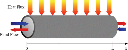
Consider a compressible fluid flowing through a pipe-shaped volume V with a rigid boundary area, exchanging mass and energy through the inlet and outlet flanges, and thermal energy through the lateral surface ( ).
Figure 1 Heat exchanger schematic diagram.
Assume that
the longitudinal dimension x is far more relevant than the other two; | |||||
the volume V is ‘sufficiently’ regular (i.e. the cross-sectional area is uniform and V is such that the fluid motion along x is not interrupted); | |||||
the fluid flow is homogeneous (i.e. the velocity of the fluid different phases have the same value); | |||||
the Reynolds number Re is such that turbulent flow conditions are assured along all the pipe, which allows one to assume uniform velocity and the thermodynamic state of the fluid across the radial direction. | |||||
When water or steam is assumed as the working fluid, the last hypothesis does not hold at very low flow rates (laminar flow regime); however, in practice most industrial processes never operate in such conditions.
It is then possible to define all the thermodynamic intensive variables with respect to the longitudinal abscissa x and time t. Within this framework, the dynamic balance equations for mass, momentum (neglecting the kinetic term), energy (neglecting the diffusion term) and partial mass can be formulated as follows:
In the case of water-steam flows it is convenient to choose pressure and specific enthalpy as the thermodynamic state variables, so that the expressions of the balance equations have the same form for single-phase and two-phase flow; all the fluid properties, such as T, ρ, ∂ρ/∂h, ∂ρ/∂p, can be computed as functions of p and h. In the case of gases, it is more convenient to choose p, T and ξ k as state variables, the latter being necessary only for variable-composition gas mixtures.
2.2 Metal wall model
Consider a cylindrical metal wall enclosing a pipe-shaped volume, exchanging thermal energy through its lateral surfaces.
The dynamics of heat flows and temperatures is described by Fourier's equation. A low-frequency approximation can be obtained by neglecting the longitudinal heat conduction, and by concentrating the heat capacity in the middle of the tube thickness, thus obtaining the following 1-dimensional model:
2.3 Heat transfer model
When a fluid flow and a metal wall come into contact, heat transfer takes place due to thermal convection and/or radiation; the heat flow is always a function of the temperatures of the interacting objects. Denoting their abscissae by x and z, it is then possible to write
3 Finite element method for time-dependent advection equation
Consider the following first-order linear partial differential equation (PDE):
EquationEquation (11) is called the time-dependent advection equation
Citation6 and it can represent the energy Equationequation (3)
and the partial mass Equationequations (4)
for heat exchangers. From now on, the first of Equationequations (11)
will be denoted as ∂u/∂t + Lu = f, where L is the appropriate differential operator.
The approximated solution of the PDE (11) can be obtained through several numerical methods; on the other hand, only methods that allow one to transform a PDE into a set of ordinary differential equations (ODEs) or differential-algebraic equations (DAEs) with respect to time are suitable to use within the Modelica framework. Within this paper the focus is on the numerical methods termed Finite Element Methods (FEM) Citation6,Citation7. Other interesting methods for the approximation of PDE (11) are the Finite Difference Method (FDM) and Finite Volume Method (FVM) Citation6,Citation8. The advantage of using FEM instead of FVM or FDM is that it can provide more accurate solution or, in specific cases, the exact nodal values for the unknown Citation6.
The FEM is based on the discretization of the solution region into basic elements. The unknown variable u is expressed in terms of assumed approximating or interpolation functions within each element. The interpolation functions are local, i.e. functions defined over smaller sub-domains extending over a few elements, and are zero everywhere else. These functions are usually very simple ones, such as low-degree polynomials, and are defined by the values of the variable at specified points called nodes. The nodal values u i of the variable and the interpolation functions for the elements completely define the behaviour of the variable within the elements: therefore, they become the new unknowns for the finite element representation of a problem. It is clear that the nature of the solution and the degree of approximation depend not only on the size and number of the elements used, but also on the interpolation functions selected Citation6.
3.1 The method of weighted residual
The Method of Weighted Residual (MWR) is a mathematical technique for obtaining finite element equations from linear and non-linear PDEs. Referring to (11), the problem solved by the MWR is to find the nodal values of an approximated solution u ℓ(x, t) so as to make the residual
3.2 Finite element basis function and space
The solution domain Ω is decomposed into elements K of mesh size ℓ
K
. The finite element space
is the finite-dimensional space of continuous piecewise-polynomial functions of degree k defined within each element K. The basic idea of the FEM is therefore to approximate the solution, belonging to an infinite-dimensional space X, with a function belonging to the N-dimensional space
.
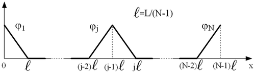
In the piecewise linear (i.e. k = 1) interpolating functions for the 1D case are depicted. The space of interpolating functions will be called hereafter W ℓ and its basis functions ϕ i (x). Then the approximated solution u ℓ(x, t) of u is expressed as
Figure 2 The ‘triangular’ basis functions ϕ j (x).
3.3 Petrov – Galerkin methods
From now on, the inner functional product notation (u, v) = ∫Ω uv dΩ will be used. By expanding (13) and properly choosing the weighting function space, the Petrov – Galerkin (PG) approximation of the PDE problem (11) consists in finding u ℓ ∈ W ℓ such that
EquationEquation (15) has to be satisfied for any v
ℓ ∈ V
ℓ, that is it has to be satisfied for all the functions of any basis of the space V
ℓ itself; the basis functions of V
ℓ will be denoted as {ψ
i
|i = 1, …, N}. The functional space V
ℓ is termed the space of test or weighting functions. Then, being {ϕ
j
|j = 1, …, N} a basis for the space W
ℓ, and substituting (14) into (15), a set of N ODEs for the unknown vector U(t) is obtained:
The (standard) Galerkin method is a particular case of the PG method, where the test function space V
ℓ is chosen to be the same as the approximating function space W
ℓ, so that M
ij
= (ϕ
j
, ϕ
i
), Aij
= (Lϕ
j
, ϕ
i
), F
i
(t) = (f, ϕ
i
). The application of the standard Galerkin method to advection-dominated problems (as the one considered) may lead to solutions showing non-physical oscillations due to numerical effects; to overcome such a problem it is possible to use a stabilized PG method. The basic idea of stabilization methods is to relate the functional space V
ℓ to W
ℓ through a differential operator L
ℓ somewhat related to the differential operator L, that is V
ℓ = {w
ℓ + L
ℓ
w
ℓ|w
ℓ ∈ W
ℓ}. The
Equationequation (15) thus becomes
If the operator L is linear and the function f is bounded over Ω (which is the case of the HE equations), then the existence and uniqueness of the solution is guaranteed Citation6; moreover, it is also possible to show that
3.4 Treatment of boundary conditions
The boundary conditions (BCs) can be imposed in two different ways.
-
Strong formulation (sf): the boundary conditions are enforced directly in the definition of the space W ℓ of the admissible solutions, while the test functions vanish on the boundary. The boundary conditions are satisfied on all the nodes lying on ∂Ωin.
-
Weak formulation (wf): the boundary conditions are enforced indirectly in the unknown nodal values of the approximated equation. The boundary conditions are not imposed exactly at all nodes of ∂Ωin, but a suitable linear combination between them and the residual of the PDE is enforced instead. Therefore, the problem formulation becomes: for any t ∈ [0,T] find u ℓ ∈ W ℓ such that
where g ℓ is the approximation of the boundary value in the space W ℓ. It is important to note that the additional integral terms can be easily computed in the 1-dimensional case since ∂Ωin is a finite set of points (at most two: x = 0 and x = L).
in the wf the nodal values on the boundary are unknown and therefore the number of finite element equations to be solved is higher than that obtained from the sf; | |||||
in the case of flow reversal (β changes sign in
Equationequation (11) | |||||
4 FEM model for single-phase fluid flow
In this section it will be shown how the numerical methods outlined in section 3 can be applied to the balance equations, so as to transform them into a set of DAEs that can be used directly in Modelica models.
A full discretization of the balance equations would lead to a very detailed model representing also the high frequency dynamics of pressure and flow rate waves, travelling at the speed of sound, which arise from the coupling of (1) and (2). On the other hand, the most relevant phenomenon in power generation systems is the slower dynamics associated to the heat transfer with the fluid velocity. These considerations led to the following approximations: the fluid pressure in
Equationequations (1), Equation(3)
and Equation(4)
has been assumed uniform and equal to the value at either the left or right boundary, while the flow rate in (2) has been assumed uniform and equal to the value at the right or left boundary, respectively. Finally, if the fluid composition varies slowly with respect to the residence time in the HE, it is possible to assume a corresponding linear distribution from the inlet to the outlet; otherwise, if necessary, it is possible to represent the composition with the same accuracy as the specific enthalpy, even though this can greatly increase the computational burden if the number of species is high.
The discretization of the spatial domain [0, L] is based on a grid of uniformly spaced elements of length ℓ = L/(N − 1), where N (≥ 2) is the number of nodes. Linear FEM interpolating functions have been chosen ( ); their analytical expression is
The stabilized PG Method termed GALS (Galerkin/Least-Squares), which has been proven to be the most suitable in the advection-dominated case Citation9, has been applied to obtain the test functions:
In this section, the model will be formulated assuming that no phase changes occur; this hypothesis will then be removed in the next section. Therefore, for the moment being, h, T, ρ, w, ξ k and φe are assumed linear on each element, so that they can be expressed using the base functions with the following general expression:
4.1 Energy balance equation
Consider the energy balance equation for the HE:
The application of a PG method, with weakly imposed boundary conditions, leads to a set of N ODEs:
The matrices C and K, enforcing the boundary conditions into
Equationequation (25), depend on the inflow boundary ∂Ωin. It can be noted that, in the 1D case, the inflow boundary is made up by at most two points (x = 0 and x = L), depending on the fluid mass-flow rate direction. Suppose, for example, that the inflow boundary is simply x = 0:
4.2 Mass balance equation
Consider the mass balance equation for the HE:
In the case of gases, the pressure p, the temperature T and the mass fractions ξ k have been chosen as the thermodynamic state variables, so that
4.3 Dynamic momentum equation
Consider the dynamic momentum balance equation for the HE:
The inertial term, to be properly computed, requires the differentiation of the discretized mass balance
Equationequation (32) to obtain the values of [wdot](x, t) in each node; this in turn requires the knowledge of the second-order time derivatives of pressure and specific enthalpy to obtain the time derivative for ρ
p
and ρ
h
, greatly increasing the complexity of the model and requiring additional symbolic differentiation of the model equations. When one-phase flow is considered, the non-uniformity of [wdot](x, t) has a small effect on the pressure drop, so that it is possible to approximate it with its value at either boundary value:
The friction term Δp F depends on the nodal values of C f which, assuming the Reynolds number is sufficiently high, are approximately constant; for medium-range values of Re, C f can be computed e.g. by Colebrook's equation. When dealing with water/steam or gas flows in industrial plants, the transition and laminar regimes correspond to very low pressure drops, which need not be computed with high accuracy, since they are usually negligible compared to the lumped pressure drops, e.g. in valves; therefore, a minimum value of Re = 2100 can be assumed when computing C f. Last, but not least, a small linear friction term must be added to enhance numerical stability at low or zero flow rate; the parameter w 0 should be much smaller than the nominal flow rate, so that the added term is negligible during normal operation. Therefore, the friction term becomes:
Finally, the fluid head term can be computed with the following expression:
4.4 Partial mass equations
Consider the partial mass balance equations for the HE:
In case the fluid composition needs to be represented with the same accuracy as the specific enthalpy, the application of a PG method, with weakly imposed boundary conditions, leads to a set of N ODEs for each of the N s partial mass equations:
If a linear distribution between the inlet and the outlet can be assumed, then the application of a PG method, with weakly imposed boundary conditions, leads to a set of 2 ODEs for each of the N s partial mass equations; the matrix expression of such equations is still (43), the only difference being that Y, B, C and Kk are now 2×2 matrices with L in place of ℓ.
The number of ODEs can be further reduced to one for each partial mass equation if a finite volume approximation is adopted for
Equationequations (4).
5 Model extension for two-phase fluid flow
In order to handle correctly the phase changes along the HE, the assumption that w, ρ, ρ h and ρ p are linear on each element are no longer valid; the discretized balance equations must then be suitably modified. The discussion is limited to constant composition fluids (i.e. water – steam) for simplicity reasons.
5.1 Energy balance equation
The assumption that the fluid density ρ is linear on each element is no longer acceptable where phase changes occur. For example, consider an element where a liquid/two-phase transition occurs: the specific enthalpy can still be regarded as linear on the element, while the density varies with a different space derivative before and after the transition, as shown in . On the other hand, the density is still continuous over the element and can be regarded as varying linearly before and after the transition, although with different slopes. The same consideration applies also to the mass flow rate w.
Figure 3 Interpolation ‘correction’ to account for phase changes.
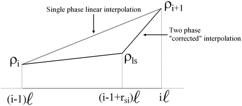
To overcome such a shortcoming, it is possible to locally ‘correct’ the interpolation of the considered quantities in case of phase transition, by using additional functions. Assuming at most one phase transition per element, the fluid density and mass-flow rate can be represented with the general expression
When approximation (44) is introduced into the finite element discretization of the energy balance equation, the following differential matrix equation is obtained:
5.2 Mass balance equation
The assumption that the density derivatives with respect to specific enthalpy and pressure (ρ h and ρ p ) are linear on each element is again not acceptable when phase changes occur: besides being non-linear, they are even strongly discontinuous.
The expression of the fluid density as a function of the pressure p and specific enthalpy h in a homogeneous two-phase flow can be obtained starting from the specific volume v as follows:
Expressions (32) and (51) can be used in case the fluid is either single-phase or two-phase over an entire element. In case a phase change occurs on the kth element a suitable combination of these expression can be used, reducing the intervals over which the integrals are computed.
For example, consider a transition from liquid to two-phase on the kth element (i.e. hk < h l and h l ≤ h k+1 ≤ h v), the discretized mass equation over such an element is
in ϒ
k
, h
l and | |||||
in ϒ2ph k , h l is used instead of hk . | |||||
5.3 Dynamic momentum equation
The modifications of the dynamic momentum equation involve primarily the friction term Δp F. That term depends on the nodal values of C f, which need to be computed with the appropriate correlations, depending on the state of the flow in each node (one-phase versus two-phase).
6 Modelica implementation
The model described in this paper has been included in the ThermoPower library Citation4,Citation5, a Modelica library developed at Politecnico di Milano for the modelling of thermal power plants. The library is based on first principle models and it fully exploits the features of the Modelica language to provide highly readable and extensible models of process components, with a customisable level of detail. Complex dynamical models can be built simply by connecting the basic components, according to the modelling strategy described in Citation10.
The main benefit of providing a Modelica implementation of the models described in the previous sections is that it is straightforward to combine them with models of other physical devices (such as pumps or valves) or physical phenomena (such as heat transfer across a thick pipe wall), which are already provided by reusable component libraries such as Citation4, in order to obtain models of complex plants.
6.1 Finite element models
The equations of finite element models are readily transformed into Modelica code; for example, (46) becomes:
The definition of the involved matrices is made through loops, as shown in the case of matrix M:
-
M[1, 1] = l/3 − l*alpha_sgn/4;
-
M[N, N] = l/3 + l*alpha_sgn/4;
-
M[1, 2] = l/6 − l*alpha_sgn/4;
-
M[N, (N − 1)] = l/6 + l*alpha_sgn/4;
-
if N > 2 then
-
for i in 2: N − 1 loop
-
M[i, i − 1] = l/6 + l*alpha_sgn/4;
-
M[i, i] = 2*l/3;
-
M[i, i + 1] = l/6 − l*alpha_sgn/4;
-
M[1, i + 1] = 0;
-
M[N, i − 1] = 0;
-
for j in 1:(i − 2) loop
-
M[i, j] = 0;
-
-
end for;
-
for j in (i + 2): N loop
-
M[i, j] = 0;
-
-
end for;
-
-
end for;
-
-
end if;
Since most of the matrix entries are zero, the matrix notation for the FEM equations might appear an inefficient formulation from a computational point of view; this is actually not the case, since efficient Modelica compilers can simplify the corresponding set of ODEs by expanding the differential matrix equations to the corresponding scalar form, and then removing all the terms which are multiplied by zero. Furthermore, when all the matrix elements are constant expressions (as in the case of M) the actual computation of its non-zero elements can be performed once and for all during the initialization phase of the dynamic simulation.
The models can be customised through several parameters: the HE geometry can be fully specified (length, diameter, height); the dynamic momentum term ∂w/∂t can be switched off to avoid fast pressure oscillations; different correlations are available for the computation of the C
f coefficient; the compressibility effect deriving from the discretization of
Equationequation (1) can be associated to either the upstream or downstream pressure; the numerical stabilization coefficient α can be chosen in the interval [0, 1].
6.2 Model encapsulation
Models can interact only through connectors: on one hand, only connector variables are visible to the outside world; on the other hand, they completely define the boundary conditions for the model equations.
Two different kinds of connectors are required, one for the fluid side inlet and outlet flanges and the other one for the heat flux through lateral surfaces. Their definition is:
-
connector FlangeA
-
Pressure p “Pressure”;
-
flow MassFlowRate w “Mass flow rate”
-
parameter Integer nXi = 0 “Number of independent mass fractions”;
-
output SpecificEnthalpy hAB “Specific enthalpy of fluid going out”;
-
input SpecificEnthalpy hBA “Specific enthalpy of entering fluid”;
-
output MassFraction XAB[nXi] “Composition of fluid going out”;
-
input MassFraction XBA[nXi] “Composition of entering fluid”;
-
end FlangeA;
-
connector FlangeB
-
Pressure p “Pressure”;
-
flow MassFlowRate w “Mass flow rate”;
-
parameter Integer nXi = 0 “Number of independent mass fractions”;
-
input SpecificEnthalpy hAB “Specific enthalpy of entering fluid”;
-
output SpecificEnthalpy hBA “Specific enthalpy of fluid going out”;
-
input MassFraction XAB[nXi] “Composition of entering fluid”;
-
output MassFraction XBA[nXi] “Composition of fluid going out”;
-
end FlangeB;
-
connector DHT
-
parameter Integer N “Number of Nodes”;
-
Temperature T[N] “Temperature”;
-
flow HeatFlux phi[N] “Heat Flux”;
-
end DHT;
The fluid side model has a FlangeA connector corresponding to x = 0, a FlangeB connector corresponding to x = L and a DHT connector for the heat flux through the lateral boundary. The input variables are used within the model to enforce the BCs at the inflow boundaries, by setting the correct entries for C and K according to (28); the output variables make the fluid state at the outflow boundaries available to the connected models. Flow reversal is supported, provided that a connection is always made between an A-type and a B-type connector.
The same DHT connectors can be used for the thermal models described in section 2.2, while the Flange connectors can be used for all the other models of fluid-handling components such as pumps, valves, etc.
6.3 Aggregate models
Consider now, as an example, the simple heat exchanger sketched in . From an object-oriented point of view, the model of this plant can be obtained by connecting:
the finite-element models of the two fluid flows; | |||||
the models of the heat transfer through the boundary layers, which are readily obtained from
Equationequations (9) | |||||
the model of the metal wall, obtained from
Equationequations (5) | |||||
the models of valves, which are basically suitable algebraic equations between the flow rates and the pressure drops; | |||||
the model of the ambient boundary conditions, which prescribe a certain pressure (or flow rate) and enthalpy at their connectors. | |||||
Figure 4 Simple heat exchanger process model.
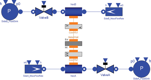
All the cited components use the same connectors described in the previous subsection. They can then be linked by connection equations, which state that variables with the same names in a connection are equal, or that the sum of the variables with the same names is zero for flow variables.
The resulting plant model is one large set of DAEs comprising both the component equations and the connection equations. It is obvious that the full system of equations can have a very different structure depending on what components are actually connected to the finite-element fluid flow models.
The index of the full DAE system depends again on the kind of components which are connected together. For example, the above-mentioned case corresponds to an index-1 problem. However, suppose that the heat transfer coefficient between the fluid side A and the metal wall is so high that it could be considered as infinite. It could then be possible to change the corresponding boundary layer model to:
In this case, an algebraic constraint is enforced between the state variables of the metal wall model and of the fluid flow model, so that the full DAE system has now index 2. A Modelica tool can then employ symbolic manipulation algorithms, such as the dummy derivative method Citation11, to transform the system to an equivalent index-1 formulation, and then use suitable numerical integration packages, such as DASSL Citation12, to solve the corresponding set of equations. It is important to point out that the finite-element declarative model of the fluid flow remains exactly the same in both cases.
7 Simulations
The simulation results reported here have been obtained with water/steam HE models; the medium model is the standard IAPWS97 model provided by the free Modelica.Fluid library Citation13. Several specific configurations have been set up in order to investigate some aspects of the model behaviour in typical layouts, using the Dymola simulation tool Citation14. The most significant results are reported here; all the test set-ups are included in the ThermoPower library and are available on-line. The FEM models have also been cross-validated with their finite-volume counterparts (not described in this paper), showing a good agreement for high values of N. It is worth pointing out, however, that the results of finite element models are actually more accurate, with respect to the original partial differential equations, since they lack the diffusive effects which are inherent to the finite-volume approach. In all the simulations, the HE has a length of 10 m and radius 1 cm, and is discretized with N = 20 nodes.
The first simulation is aimed essentially at testing the energy balance equation with an incompressible fluid, i.e. liquid water. A flow model, subject to a uniformly distributed external heat flux, is connected to a mass flow rate source with variable temperature, and to a discharge valve. The fluid involved is liquid water at temperatures between 297 and 322 K, at pressures from 1.67×10⁵ to 2×10⁵ Pa; the mass flow rate is comprised in the interval 0.2 – 0.3 kgs−1, corresponding initially to a fluid transit time of 10 s.
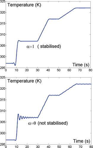
At time t = 0 s the inlet specific enthalpy is increased from 105 to 1.42×10⁵ Jkg−1; at time t = 30 s the energy flux is increased from 0 to 1.25×10⁴ W m−2; at time t = 50 s the flow rate is reduced from 0.3 to 0.2 kg s−1. In the HE outlet temperature is reported for two different values of the numerical stabilization coefficient α. The exact solution of (3) (assuming ρ constant) would lead to a delayed step variation of the outlet temperature at t = 10 s and to ramp variations starting at times t = 30 s and t = 50 s; the simulation results for α = 1 are in good accordance with such behaviour (save for a small temperature undershoot), while the results obtained with α = 0 show significant numerical oscillations.
Figure 5 Heat exchanger outlet temperature transients.
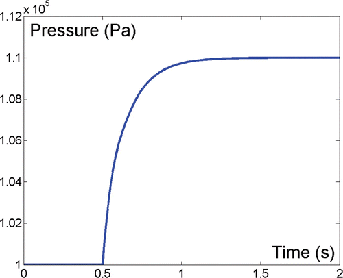
The second simulation is aimed at testing the mass balance equation. The experimental layout is similar to the first one; the fluid is superheated vapour, to highlight the fluid compressibility effects.
At time t = 0.5 s the inlet flow rate is increased by 10% (starting from the value 1×10² kgs−1) with a step variation: the fluid pressure increases with the first-order transient shown in , whose time constant is in good accordance with the theoretical value obtained by modelling the HE as a simple plenum having the same volume.
Figure 6 Heat exchanger pressure transient.
The third test involves a tubular counterflow HE with two concentric fluid flows: the internal side (diameter 20 mm) contains high-pressure liquid water which is heated by the superheated steam flowing on the steam side (diameter 29 mm); the two sides are separated by a wall 3 mm thick. The liquid and the metal have the same heat capacity, which is 100 times that of the steam; furthermore, the heat transfer coefficient between the steam and the metal is very high (about 105 Wm−2 K−1) so that temperature variations in the steam flow travel with a velocity which is two orders of magnitude less than the fluid velocity, due to the strong thermal interaction with the metal wall. The HE is modelled by connecting two flow models (vapour side and liquid side), the metal wall model and two convective heat transfer models (see ).
At time t = 50 s the steam inlet enthalpy is increased by 105 J kg−1: the outlet temperature of the liquid side starts increasing immediately, while the outlet temperature of the vapour side increases after a delay determined by the metal wall heat capacity ( ).
Figure 7 Heat exchanger temperatures.
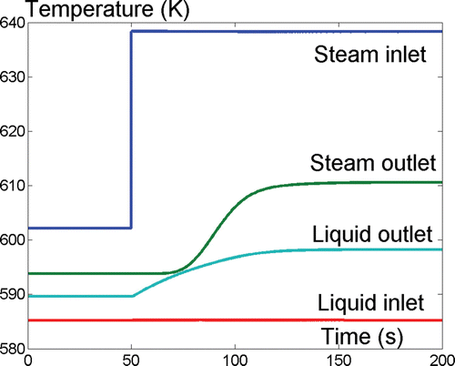
This simulation shows that the coupling of two FEM-based flow models through the heat transfer and metal wall models does not affect the numerical stability, even for large values of the heat transfer coefficient; this is not obvious a priori, as the heat flow φe(x, t) in (3), computed by the external heat transfer object, is no longer a given function but now strongly depends on the fluid unknown enthalpy h(x, t). Further tests with different stabilization coefficients confirmed the absence of numerical instabilities.
The last test investigates the dynamic behaviour of the two-phase model. The flow model is connected to a fixed mass flow rate source at the inlet and to a valve at the outlet; a uniform heat flux is applied on the lateral surface. The operating fluid is water (both in liquid and vapour phase), at a pressure of about 6×10⁶ Pa with a mass-flow rate of about 0.1 kgs−1. The fluid entering the HE is subcooled water with a specific enthalpy of 7×10⁵J kg−1 (corresponding to about 438 K).
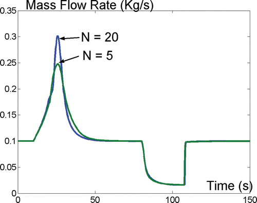
Initially the heat flux is zero, so that the tube is filled with liquid water; from time t = 10 s to t = 20 s the heat flux is increased to 2.5×10⁵ W m−2. At the end of the transient the fluid in the HE is liquid in the first 2 m, then a two-phase mixture for 6.5 m and superheated vapour in the last 1.5 m. At time t = 80 s the heat-flux is reduced to zero in 2 s. The values of the specific enthalpies at x = 0, x = L/2 and x = L are reported in , along with the saturated liquid and vapour values. shows the corresponding mass-flow rate at the outlet: in the first part of the transient, the fluid expansion due to the increased heat flow leads to a transient increase of the outlet flow rate; the opposite happens when the heat flow is reduced. Note that, despite the strong nonlinearity of the fluid properties (the density changes by more than an order of magnitude between liquid and vapour), no discretization artifacts are visible in the simulation; this remains true even for coarser discretizations (e.g. N = 5).
Figure 8 Heat exchanger once-through configuration: specific enthalpy.
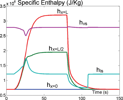
Figure 9 Heat exchanger once-through configuration: outlet mass-flow rate.
8 Conclusions
The modelling of heat exchangers with Finite Element Methods, using object-oriented declarative modelling languages (such as Modelica), which support models described by DAEs, has been discussed in this paper.
After a general review of FEM methods in general, Petrov – Galerkin's method has been applied to obtain a discretized DAE model of 1-dimensional heat exchangers with one-phase flow. The model has subsequently been extended to deal also with two-phase flow conditions.
The models obtained here have been implemented in the open-source ThermoPower Modelica library, which is being developed for system modelling of power generation processes, and is publicly available on the Web Citation4. The result of some validation simulations have been presented, confirming the soundness of the proposed approach.
References
- Incropera , F. P. and DeWitt , D. P. 1985 . Fundamentals of Heat and Mass Transfer , New York : John Wiley & Sons .
- Mattsson , S. E. , Elmqvist , H. and Otter , M. 1998 . Physical system modeling with Modelica . Control Engineering Practice , 6 : 501 – 510 .
- Modelica Association . http://www.modelica.org/
- Casella , F. and Leva , A. Modelica open library for power plant simulation: design and experimental validation . Presented at Proceedings of the 3rd International Modelica Conference . 3 – 4 November 1993 . pp. 41 – 50 . Linköping, , Sweden http://www.modelica.org/Conference2003/papers/h08_Leva.pdf
- Casella , F. and Leva , A. 2006 . Modelling of thermo-hydraulic power generation processes using Modelica . Mathematical and Computer Modeling of Dynamical Sytems , 12 : 19 – 33 .
- Quarteroni , A. and Valli , A. 1997 . Numerical Approximation of Partial Differential Equations , Berlin : Springer Verlag .
- Johnson , C. 1987 . Numerical Solution of Partial Differential Equations by the Finite Element Method , Cambridge : Cambridge University Press .
- Aime , M. L. Engineering methods and tools for modeling and simulation of power generation plants , Politecnico Di Milano 1999, PhD thesis
- Hughes , T. J.R. , Franca , L. P. and Hulbert , G. H. 1989 . A new finite element formulation for computational fluid dynamics: VIII. The Galerkin/Least-Squares method for advective-diffusive equations . Computer Methods in Applied Mechanics and Engineering , 73 : 173 – 189 .
- Leva , A. and Maffezzoni , C. 2003 . Thermal Power Plant Simulation and Control , Edited by: Flynn , D. 17 – 60 . London : IEE .
- Mattsson , S. E. and Söderlind , G. 1993 . Index reduction in differential-algebraic equations using dummy derivatives . SIAM Journal of Scientific and Statistical Computing , 14 : 677 – 692 .
- Petzold , L. R. , Brenan , K. E. and Campbell , S. L. 1989 . Numerical Solution of Initial-Value Problem in Differential-Algebraic Equations , Amsterdam : Elsevier, North-Holland .
- Elmqvist , H. , Tummescheit , H. and Otter , M. 2003 . Object-oriented modeling of thermo-fluid systems . Presented at Proceedings of the 3rd International Modelica Conference . 3 – 4 November 2003 . pp. 269 – 286 . Linköping, , Sweden http://www.modelica.org/events/Conference2003/papers/h40_Elmqvist_fluid.pdf
- Dymola . Dynamic Modelling Laboratory , Lund, , Sweden : Dynasim AB .
Appendix A: matrix expressions